Digital library
General technical disciplines / Cutting tools / 7.6.4.
Features of Hobs for Cutting Hobs Hobs can be cut by hobs, fly cutters and finished by hobs. Hobs operate with radial or tangential feed (Fig. 7.36, a, b).
When working with radial feed, the cutter is installed so that the teeth touch the outer surface of the wheel rim. When the cutter and the workpiece rotate, their axes are then brought closer together to a value that provides the required dimensions of the teeth of the wheel being cut. Subsequently, teeth are cut at a constant
at a certain center-to-center distance and when the cutter and workpiece rotate together without moving the cutter along the axis.
Rice. 7.36. Schemes for cutting a worm wheel with a hob cutter:
a) with radial feed, b) with tangential feed
With tangential feed, the axes of the cutter and the workpiece are set at the required center-to-center distance, then tangential feed is carried out along the axis, and the center line of the cutter teeth moves tangentially to the initial circumference of the wheel being cut. With such cutters, the angle of the intake cone at a length equal to 2.5...3 steps is performed to reduce the load on the first tooth of the cutter.
The tangential method of cutting wheels is less productive than the radial one, but it improves the quality of the tooth surface by increasing the number of cutter teeth in contact with the workpiece. The durability of tangential cutters is higher due to the fact that the cutting force is distributed over a larger number of cutter teeth.
To ensure geometrically correct engagement of the wheel being cut with the worm, the cutter must be profiled identically to the profile of the worm turns. The actual profiling of hob cutters processing worm wheels is no different from the profiling of hob cutters for cylindrical gears (see Fig.
section 7.1 and 7.2). The initial data for calculating the cutter are specified in the axial section of the worm: modulus, engagement angle, axial pitch, axial tooth thickness, outer diameter, average diameter, helix angle, number of worm passes, number of wheel teeth, radial clearance in the gear, diameter of the worm protrusions circle wheels, direction of worm turns.
The overall dimensions of the cutter in the cross section are not chosen arbitrarily, which is acceptable for cutters for cylindrical wheels, but depend on the diameter of the worm. The average (pitch) diameter of the cutter teeth is equal to the average diameter of the worm: the pitches of the cutter teeth and the wheel are also equal to each other. The internal diameter of the cutter is usually assumed to be equal to the internal diameter of the worm.
The helix angles on the dividing cylinder, the modules and the number of passes of the cutter and worm must match.
The outer diameter of the cutter is made larger than the outer diameter of the worm by twice the radial clearance, taking into account the allowance for regrinding (Fig. 7.37):
,
where 0.1m is the regrinding allowance, compensating for the reduction in the radial clearance in the gear while maintaining the center distance during the cutting process, regardless of the degree of regrinding of the cutter.
Rice. 7.37. Determining the overall size of a hob cutter
Since the lead-in of the cutter must be equal to the lead-in of the worm, cutters often have to be made multi-start. Therefore, the angles of elevation of the turns of cutters for worm wheels are greater than for cylindrical wheels, sometimes up to 35...400.
Depending on the shape of the worm profile, cutters for processing worm wheels can be involute, Archimedean and convolute. The choice of the type of main worm depends on the type of cutter (roughing or finishing): Archimedean - for finishing cutters, and involute and convolute - for roughing.
Rice. 4. Hob cutter with taper
By making a fence cone, we distribute the cutting work more evenly to other teeth along the axis of the cutter. As a result, the tool wears out more evenly. Fence cone length lk
1.5-2 steps are taken, and the angle
j k
= 18-30°.
The number of cutter teeth should be as large as possible. With increasing z and
the number of cutters increases, the surface roughness decreases, and the thickness of the cut layer decreases.
The number of teeth of mounted solid cutters is limited by the conditions of backing, and of prefabricated cutters - by the conditions of fastening the teeth. For hob cutters of ordinary precision z and
= 12-9 are accepted, for precision hobs
z and
= 16-12, for prefabricated backed cutters
z and
= 10-8.
The grooves that form the front surface of the teeth and the space for placing chips can be helical, perpendicular to the turns of the cutter teeth on the pitch diameter in the design section, and straight, passing through the axis if the rake angle g
= 0
, or parallel to the axis if
g ¹ 0.
Standard cutters are made with grooves of the first type. Helical groove pitch Рк =
p Dctg w
. The rake angles for the left and right cutting edges of such cutters are the same.
Cutters with straight flutes are easier to sharpen, and those made on the basis of an Archimedean worm have a smaller theoretical change in profile during regrinding. However, the rake angles for the left and right cutting edges are different. On the one hand, in the axial direction g o
= + t
, on the other hand,
g o
=
- t
.
Therefore, cutters with straight grooves are made with small helix angles t = 3-5°.
Flute depth for single flange cutters
Hk
= h and +K + r
With double backing
where h and
— cutter tooth height, usually
h and = 2.5 m ; K and K1 -
the amount of relief of the ground and unpolished part of the tooth,
K1 = (1.25 - 1.6) K; r is
the radius of curvature of the groove bottom, usually
r
= 1-3 mm.
For cutters with a modulus of more than 5 mm, as a rule, double backing is done, since due to the danger of cutting off the cutting edge of the next tooth with a single backing, a significant part of the tooth is not backed. Therefore, the first backing by the value K1
is made with a cutter before heat treatment of the cutter, and the second by a value of
K
is made with a grinding wheel after heat treatment.
It is considered normal if the length of the ground head is equal to 0.5P z ,
that is, it reaches the cutter section 2-0.
Groove angle e = 20-30°.
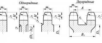
Fig.5. Milling cutter tooth profile parameters
The dimensions of the tooth profile are shown in Fig. 5. For cutters profiled on the basis of a convolute worm, the profile lies in the normal section to the turns, and its dimensions are determined in this section. The profile angle of such cutters is a and
is taken to be equal to the profile angle
a
of the original contour of the rack.
For cutters profiled on the basis of an Archimedean worm, the profile is specified in the axial section of the cutter. Due to the backing of the side surfaces, the profile angles for the left a il.
, and right
a un
. their sides will be different.
For uncorrected gearing, the pitch between the cutter teeth in the normal section is Pn
= p mn
, in the axial section
P x = P n с s t .
Tips for use
Even when using expensive, high-quality attachments for milling cutters, the working part inevitably becomes dull during the processing of workpieces. We are talking about the loss of the cutter's key qualities, which periodically need to be restored. In such situations, the only solution to the problem is proper sharpening. To do this, you will need specialized equipment that allows you to quickly restore the geometry with minimal effort and maximum accuracy.
The accuracy of all operations performed and, consequently, the quality of the product directly depend on the condition of the milling apparatus and the correct maintenance of the working element itself. Thus, the cutter is sharpened along the leading edge, and its backing is performed along the opposite part of the surface. Calculation of the degree of processing of the working part and corners is carried out taking into account the degree of wear.
There are effective ways to upgrade your tool and improve its performance after sharpening the edge. This allows you to increase productivity and at the same time ensure maximum service life of the cutters themselves. The most common and effective ways of improvement are as follows.
- The use of prefabricated structures, the elements of which are made of high-strength steel grades.
- Modernization of profile working surfaces.
- Changing the cutting pattern, as well as the geometry (including thickening) of the cutters.
It is important to consider that the wear resistance and service life of the described tool are influenced by the milling method. In particular, we are talking about the distribution of loads on the teeth
Naturally, one of the key roles is played by the properties of the tool material, based on which manufacturers are constantly looking for new options. Maximizing the service life of any hob cutter will allow you to strictly follow the technology when performing work
In addition to all of the above, it is recommended to pay attention to the characteristics of the workpiece material
Peculiarities
A hob cutter is a tool for creating spline shafts of various profiles, as well as spur gears and sprockets. Such products are made from high-speed, carbide steel grades.
The main feature of such equipment for milling cutters is not so much the shape and design nuances as the scope of their application. At the same time, they are characterized by the presence of backed, sharply sharpened teeth.
Features of the use of cutters determine the list of materials for their manufacture. Key standards and norms, including drawings indicating angles that manufacturers must adhere to, are enshrined in GOST 15127-83. Otherwise, the hob cutter will not have the necessary performance characteristics. It is worth noting that the described milling tool has a rather complex design, which directly depends on its purpose.
So, in situations with cylindrical, gear-cutting models, we will talk about the following important points.
- The basis of the future product is a cylindrical blank, which can be of any length and diameter. The parameters in this case are determined by the dimensions and design features of the future cutter.
- The working segment itself consists of teeth of the appropriate shape, which are located at a certain distance from each other. Another important element is the presence of technological grooves designed to remove removed chips.
- In the vast majority of cases, there are slight bevels at the ends that separate the working part from the fastening element of the router itself.
- Modern cutters are compatible with almost any model of special equipment due to the presence of a hole in their central part. Rotation of the tool during processing of parts is prevented by a key, the dimensions of which depend on the potential load.
The shape of the teeth is prescribed in the standards and is determined by the specific application of the tool. In particular, metal cutters with a small profile angle are often used, due to which it is possible to minimize the risk of the formation of micro-irregularities on the processed surface.
In this case, it is worth focusing on the following nuances
The use of such cutters in work significantly improves the quality of work performed
Due to the small angle, the allowance for finishing cutting is distributed more rationally. Multi-start versions are produced that are successfully used in the manufacture of wheels with a modulus in the range of 4-5 mm. The increase in feed, and therefore a significant increase in productivity, is due to the corresponding rigidity of the frame. The high quality of processing of workpieces and future products is determined by the absence of even microscopic irregularities on the surface of the teeth. It is important to consider that this type of hob cutter is intended for use on milling machines that provide rigid fixation of the working element. In this case, radial feed is recommended, which can significantly increase productivity in such situations.
At the moment, the popularity of equipment with insert elements in the form of combs is actively growing. On the special tool market, manufacturers offer models with a module in the range of 4-30 mm.
In the context of the design features of these cutters, it is important to highlight the following points:
- Alloy steel is used in the production of the main part of the equipment. In this case, the required heat resistance is achieved through various additives.
- The combs themselves are made of high-speed steel grades, the main and defining characteristics of which are maximum resistance to high temperatures and strength.
- The performance indicators of these types of milling attachments are increased many times thanks to replaceable working elements. In addition, manufacturing companies maximize the effectiveness of the tool through the use of special alloys that have certain characteristics.
Today, you can find more than a wide range of devices on sale. Their list, for example, includes prefabricated models of cutters without backing. Their main features are a 10-mm module, as well as increased, compared to more common options, angles in the tail section. Naturally, the accuracy of the work directly depends on the quality of surface grinding.
Tool designs
When producing the tool in question, the standards established in GOST 15127-83 must be taken into account (a hob cutter will otherwise not be able to ensure the high quality of the resulting surface). The product is characterized by a rather complex design, and it can differ significantly depending on the purpose of the cutter. Cylindrical hob gear cutters consist of the following elements:
- During manufacturing, a cylindrical blank is used as a base. It can have a variety of sizes and lengths, it all depends on the specific task at hand during manufacturing.
- The working part is represented by teeth that have a special shape. In this case, the teeth are located at a certain distance from each other, there are technological grooves for removing chips.
- On the end sides, as a rule, there are small bevels designed to separate the working part from the fastening element of the machine.
- Today, hob cutters can be installed on various milling machines, for which there is a hole in the central part of the product. Rotation of the tool at the time of processing the workpiece is eliminated due to the hole for the key. Its dimensions are selected depending on the load the product is designed for.
Download GOST 15127-83
The shape of the teeth is obtained in compliance with state standards. It will largely determine what parts the tool is used to produce.
Options with a reduced profile angle can be used. This tool allows you to reduce the number of micro-irregularities on the surface. Among the application features, we note the following points:
- The use of a tool with a reduced profile angle improves the cutting process. This ensures rational distribution of allowance for finishing cutting.
- There are variants of multi-start type, which can be used to produce wheels with a module of 4-5 mm.
- A significant increase in frame rigidity allows for increased feed and increased productivity. Reducing the number of microroughnesses on the tooth surface also ensures a high-quality part.
- Such a tool can only be used on machines whose dimensions allow installation. It is recommended to use a radial feed direction to significantly increase productivity.
The involute helical surface is characterized by the fact that the surface can be processed using a flat grinding wheel. When producing such a surface, a number of difficulties may arise.
The characteristics of the cutting edge may vary significantly. An example is the Archimedean helical surface, which is obtained by a straight segment with an axis intersecting at a certain angle. Mills are manufactured in accordance with GOST 8027-86, thereby ensuring the required performance characteristics. The weight of hobs varies over a wide range, depending on the type of material used in manufacturing and its dimensions.
Download GOST 8027-86
Models with a modified profile are used for cutting gears followed by shaving and grinding procedures. The design with a modified profile is characterized by the fact that the tooth is made with a thickening at the apex. Due to this, the profile angle is significantly reduced, and other tool parameters remain practically unchanged.
The front surface of the hob cutter teeth is sharpened at different angles depending on the type of processing that will be carried out. An example is rough and finish turning.
Recently, models with insert combs have been increasingly used. On sale there are versions with modules from 4 to 30 mm. The design features of such a hob cutter include the following points:
- The main part is made using alloy steel. By adding certain chemical elements, heat resistance is significantly increased. In this case, the base is created in such a way that a specific working surface can be created.
- The combs are made of high-speed steel. It is characterized by resistance to high temperatures and wear resistance.
- The use of replaceable combs significantly improves the quality of the cutting part. At the same time, manufacturers can increase the efficiency of tool use several times through the use of a special alloy.
You can also purchase prefabricated non-backed hobs. This version is characterized by a module of up to 10 mm. A distinctive feature is the increased rear angles when compared with common models. High precision is achieved by grinding the surface using special equipment
To significantly increase processing speed, prefabricated hobs with carbide teeth can be used. Recently, carbide inserts, which can withstand long-term processing, have become widespread. In this case, the module is no more than 4 mm. Installation of replacement elements is carried out in a housing with a negative rake angle, which reaches 15 degrees. The use of this design option allows you to increase productivity by 2-3 times. Most often, the tool is installed for cutting ears with subsequent shaving.
What it is?
A modular cutter is a multi-blade tool that is widely used in individual and mass production for the production of gears, gears and racks. Unlike cutters and gear-cutting combs, modular cutters have a high operating speed, do not require special equipment and provide high accuracy.
There are different designs for different technological operations and production conditions.
Disk. The main advantage is versatility. Processing can be done on any horizontal milling machines, but the part must be secured in a dividing device. Disadvantage: a lot of space is required for the tool to exit the workpiece (cutter radius plus a gap of 3–5 mm). Therefore, it is impossible to cut stepped wheels or solid chevron wheels. But you can process several workpieces at once. This significantly increases productivity and reduces the cost of manufacturing gears. But since only one cavity between the teeth can be machined in one pass, the overall cutting speed of the wheel is low.
The high accuracy of the hob cutter is due to the processing method itself. When cutting teeth, the workpiece and tool simulate gearing, a method called rolling. With this processing method, you do not need a large number of tools - the same cutter can cut wheels with different numbers of teeth. And with disk and finger cutters, their profile is transferred to the wheel depressions, which is why this method is called the copying method. In this case, all errors are transferred to the final product, so after processing, parts are often sent for grinding.
To install modular cutters on the machine, special devices are needed.
- Disc and worm models are mounted on a mandrel. To do this, they have a central hole with chamfers that simplify installation. After this, the mandrel is fixed on the spindle.
- Finger cutters have a shank in the form of a cylinder, Morse taper or a 7:24 tool taper. It can be immediately installed in the spindle.
If the mounting dimensions of the tool and the machine spindle do not match (for example, the diameters of the central hole and the spindle), then adapter bushings are used. They are standardized according to GOST. Moreover, with their help you can change the type of fastening. For example, fix a cutter with a Morse taper in a spindle with a 7:24 conical hole.
Table of hob sharpening angles
| Type of cutters | Front angle, degrees | Width of strengthening chamfer f, mm | 3rd rear angle, degrees | |||
| Basic, ? | Strengthening chamfer ?f | Tops of the tooth? | Left Side Edges ?l | Right side edge, ?п | ||
| Finely Modular | – | 6…10 | 1,25…2,0 | 1,5…2,0 | ||
| Small-module brazed and prefabricated | 10…12 | 2 | 2 | |||
| Sharpened | 15..25 | 0,6…0,8 | 10…15 | 12 | 12 | |
| With rotary teeth | ?15 | ?25 | 0,4…0,6 | 15 | 6 | 4 |
| Prefabricated and composite with backed teeth | 10…25 | 0,4. 0,8 | 5,5 | 5,5 | ||
| Brazed and assembled finishing worm gears | -30 | 20 | 5 | 5 | ||
Table 31
| Design parameter | Outer diameter D0, mm | ||
| 25 | 32 | 50 | |
| Module, mm | 0,2; 0,3; 0,4; 0,5 | 0,2; 0,3; 0,4; 0,5; 0,6; 0,7; 0,8 | 0,4; 0,5; 0,6 , 0,7; 0,8; 0,9; 1,0 |
| Bore hole diameter d, mm | 8 | 13 | 22 |
| Diameter of shoulders D1, mm | 16 | 20 | 32 |
| Number of teeth at end z | 10… 12 | ||
| Cutter length L, mm | 10; 16 | 20 | 32 |
| Length of cutting part L1, mm | 8; 12 | 15 | 25 |
The design of a cutter with carbide knives is shown in Fig. 33. Sharpened knives 3 are installed in the longitudinal gases of the cutter body 1 and secured in them using screws 5, spacers 4 and sectors 2. Since the width of the knife is equal to the axial pitch of the cutter, the location of the knives in the cutter body strictly along the helical line is ensured using sectors 2 with projections, each of which has a height difference of ?.
Non-sharpening polyhedral plates made of hard cross-links have become widespread as cutting elements of various metal-cutting tools. The use of such plates marked the beginning of a new progressive direction in the design of instruments. The use of non-sharpening plates as a cutting element allows increasing cutting conditions and ensuring ease of use, especially for complex metal-cutting tools.
Carbide hobs with sharpened cutting elements have a number of disadvantages. Milling cutter teeth with sharpening angles less than 90° do not ensure reliable operation of the cutter when cutting steel gears due to frequent chipping of the outer and transition cutting edges. Brazed cutter teeth are subject to stress from soldering and cannot be properly processed with diamond abrasive tools. One of the significant disadvantages of such cutters is also the need to regrind the cutter teeth along the rear surfaces each time the cutters are sharpened.
Rice. 33. Sharpened prefabricated carbide hob cutter
The above disadvantages are eliminated by the use of rotary, non-grindable carbide alloy plates as cutter teeth - These plates have a sharpening angle of 90° or more, making it possible to use more wear-resistant grades of carbide alloys (T15K6, etc.) for them and allow them to be completely processed only with diamond wheels .
The use of rotary, non-regrindable plates as hob cutter teeth is advisable for modules of 1.5…4.0 mm.
The most effective use of hobs with rotating non-grinding plates-teeth for high-speed gear hobbing for shaving or gear grinding of steel gears with a hardness of up to HB 350. In Fig. Figure 34 shows such a 2.5 mm module cutter with an outer diameter of 117 mm.
Diamond-shaped plate-teeth are installed in the grooves of the body, allowing the cutting sides to be used four times without regrinding. After wear on four sides, the profile can be restored many times by grinding. Taking into account four rotations of the tooth plates, regrinding and their possible rearrangements, a set of four pieces can provide the cutter with up to 40 periods of durability. The length of the teeth decreases by 0.5 mm after each grinding and then they can be used with replaceable pads in the old body or in a new one. The tooth plates are installed in the housing with a protrusion of up to 1 mm relative to the supporting side of the ridges.
Rice. 34. Carbide hob cutter with non-sharpenable inserts
Purpose
Modular cutters are used on gear-cutting milling machines, universal turning machines with a special head, multi-operational CNC machines and some other types of equipment. With their help you can make:
- cylindrical gears with straight, oblique and circular teeth;
- bevel gears of different sizes;
- chevron wheels with different groove sections between the teeth;
- gears with a cycloidal tooth profile - special cutters are required for their manufacture;
- gear racks;
- gear shafts of various shapes and configurations;
- gauges for measuring the accuracy of gears.
Processing workpieces made of different materials requires different tools.
- For workpieces made of carbon steels, cutters made of steel grades 9ХС, ХВГ, ХВСГ and others are used. They are subjected to surface hardening with high frequency currents, so the hardness of the cutting edges increases to 62–64 HRC.
- Workpieces made from structural materials are processed with cutters made from high-speed steels R6M5 and R6M3. The hardness of the cutting edges is 63–65 HRC. Such tools have a higher cost.
- Compound cutters are used to cut teeth on alloyed parts. The body of the tool is high-strength steel, and the cutting plates are made of hard alloys. They are secured mechanically.
To obtain a high-quality product, milling is carried out in 2 approaches: roughing and finishing. The precision quality of the processed surface is 9–10. The resulting products can be immediately installed on the machine or sent for further grinding. The quality of the machined surface also depends on the size of the tool. The larger the diameter of the modular cutter, the better the cutting conditions and the higher the accuracy of the product. Tool parameters are strictly regulated by documents and indicated in catalogs.
Cutting worms and worm wheels
Worm gears are widely used in mechanical engineering due to their compactness, silent and smooth operation.
The cross-section of the turns of a cylindrical worm with an axial plane is a rectilinear rack, while for a globoid worm it is a circular rack.
Among cylindrical worms, the screw worm (with an Archimedean spiral), which is an ordinary screw with a trapezoidal thread, has received the greatest use for non-critical gears (Fig. 106, a). Despite the ease of processing, a worm pair with such a worm has low efficiency and is subject to rapid wear, so it is used in non-critical, low-speed and lightly loaded gears. Another type of cylindrical worm is an involute worm (Fig. 106, b). It is like a cylindrical gear with helical involute teeth.
In the section of the worm by planes perpendicular to the axis of the main cylinder, involutes are obtained. Such worm pairs are often used in critical transmissions at high loads and speeds.
A simple type of cylindrical worm is a worm with a rectilinear profile in the normal section of the coil and with an involute side of the coil in the section transverse to the axis (Fig. 106, c). Such a worm is called convoluted and is a type of involute worm. These worms are easier to process than involute worms, and provide sufficient accuracy of engagement of the worm gear, have high efficiency and wear resistance.
Globoid worms have a large contact surface between the turns and the teeth of the worm wheel, which reduces pressure and, consequently, wears the surfaces of the teeth of the worm pair. Due to the complexity of manufacturing, they are widely used only in high-power transmissions.
The simplest and cheapest way to make turns of a worm with an Archimedean spiral is cutting with a cutter on a screw-cutting lathe. The cutter is installed so that its straight cutting edge lies in the axial plane of the worm. In this case, the helical surface is formed by rotation of the workpiece and the movement of the cutting edge passing through the axis of the worm. The helical surface of such a worm is called Archimedean, since in the section of the worm perpendicular to its axis, an Archimedean spiral is obtained (Fig. 106, a).
In Fig. 106, b shows a method for cutting turns of an involute worm. In this case, the cutter is installed so that one of its straight cutting edges is located above, and the second below the axial plane of the worm by the radius r0 of the main cylinder of the helical involute surface.
The formation of a helical surface occurs when the workpiece rotates and the cutting edge of the cutter moves tangentially to the forming cylinder of diameter 2r0. Such a helical surface is called involute, since an involute is obtained in the end plane of the worm.
When cutting turns of a convolute worm (Fig. 106, c), the cutters are installed so that their cutting edges are in a plane normal to the helical surface.
The formation of the helical surface of a convolute worm occurs in the same way as the surface of an involute worm - during the movement of the straight cutting edge of the cutters, when it remains tangent to the forming cylinder.
The described method of cutting worms with cutters is accurate, but ineffective. In mass production, worm turns are performed by milling with disk or worm cutters, as well as by rolling with cutters.
Milling with disc cutters is carried out on special thread-cutting machines. The cutter has a cavity profile in a normal section and is installed at an inclination angle of the helix β (Fig. 107). The full depth of the screw is milled at once. For one revolution of the product, the cutter moves by one step. Due to the distortion of the profile of the turns, cutting with disk cutters is a preliminary processing of the worm profile.
Along with cutting worms with a disk cutter, various types of worms are processed with a hob cutter on conventional gear milling machines. The machine is set up to cut a cylindrical gear with helical teeth, the number of which is taken to be equal to the number of worm passes.
The most accurate and highly productive way of processing worms is cutting the worm with a cutter (Fig. 108). The cutter 1, installed relative to the axial plane of the cut worm 2, has a feed movement along the axis of the worm. In addition, the cutter and the worm are given a rotational rolling motion by adjusting the kinematic chain of the machine. As a result of the combination of these movements, all the turns of the worm are cut.
To cut worms with a helix angle of less than 5-6°, the cutter is made with straight teeth, and for a helix angle of more than 5-6° - with oblique teeth. However, the need to manufacture cutters for each elevation angle of the turns of the cut worms increases the cost of production preparation, so the use of this method is economical only in large-scale or mass production.
The most widely used when cutting globoid worms are multi-cutting heads, which perform a rotational movement in a plane passing through the axis of the worm (Fig. 109).
Profiling cutters 1 and 4, the cutting edges of which have the profile of the main section of the coil, process the coil along its lateral sides, the cutter 3 of the head grinds the worm along the outer globoid.
The operation of cutting a worm with cutting heads is divided into two transitions. In the first transition, processing is carried out with radial feed of the table to the nominal interaxial size. The first transition is intended for cutting a cavity to the depth of the profile. The second transition is performed at a constant center distance and is designed to obtain a given coil thickness with a surface roughness of at least 2.50 microns (6th class). The sides of the coil are processed alternately, with a circular feed of the cutters.
Before finishing, it is necessary to deepen the cutter into the worm being cut to remove the allowance for finishing cutting. This is done by rotating the machine table with the cutting head through the differential chain. Processing is carried out with a cutting speed v ≤ 1 m/min and a feed to the cutter s = 0.02-0.04 mm with abundant cooling with a mixture of vegetable and animal oils. For finishing, the recess on the side of the coil is 0.5-1 mm.
After cutting the turns, the worm is heat treated, cemented, hardened and tempered to a given hardness.
The grinding of the turns is carried out on a gear-cutting machine with a special grinding head, which rotates the axis of the grinding wheel to the corresponding angle of elevation of each point of the turn. Finishing of globoid worms is carried out by lapping or rolling with a hardened polished roller on a special machine. Surface roughness reaches 0.08 microns (10th class)..
The processing of worm wheels is carried out on gear hobbing machines using hob cutters using three methods:
- 1) radial feed method;
- 2) tangential feed method;
- 3) combined method.
With the radial feed method, workpiece 1 (Fig. 110, a), being constantly engaged with hob cutter 2, makes a radial feed to the cutter to the set size, while the cutter makes only rotational movement. The worm wheel produces a more correct tooth profile when the hob cutter is fully engaged with the workpiece.
The disadvantage of this method is that the hob cutter does not work with all cutting edges and only the teeth of the middle part of the cutter wear out.
With the tangential feed method (Fig. 110, b), the workpiece of the worm wheel 1 is set to the size of the center-to-center distance A and the cutter is inserted with the workpiece by axial movement. Milling cutter 3 has a conical intake part and, working with all cutting edges, wears out evenly. During the cutting process, the cutter not only rotates, but also moves forward along its axis. In this case, the workpiece, in addition to the main rotational movement associated with engagement, has an additional rotational movement depending on the axial movement of the cutter, otherwise the teeth of the hob cutter cut off the teeth of the worm wheel.
The combined method of cutting worm wheels is a sequential combination of the first two methods. Moreover, the radial feed method is used for preliminary cutting of teeth, and the tangential feed method is used for final processing.
With the combined method, both hob cutters and profile cutters are used. The use of profile cutters for final processing of the worm wheel provides the highest accuracy.
The processing of globoid gear teeth is similar to the processing of conventional worm wheels and is performed with a special tool. In Fig. 111 shows a cutting diagram for a globoid worm wheel and the design of the cutter. Cutting the teeth of a worm globoid wheel is carried out in two transitions - cutting to the depth of the profile with radial feed of the table to the nominal center-to-center size and finishing cutting at a constant center-to-center size with circular feed.
Before the finishing pass, the cutter is deepened into the wheel being cut to remove allowance for finishing cutting. This is done by turning the machine table with the wheel being processed through the differential chain. Milling ends when the specified tooth thickness and surface roughness are not lower than 20 microns (5th class).
Finishing of globoid worm wheels during mass production is carried out by shaving with a globoid worm wheel (Fig. 112); The allowance for shaving does not exceed 0.05–0.1 mm. In individual production, this method is not justified, since such a shaver is an expensive tool.
Design Features
A modern gear cutter is presented in a shaped version with a backed tooth. Among the design features, we note the following points:
- The device has a central hole, which is intended for installing a mandrel. The disc gear-cutting modular cutter is mounted in the spindle using a mandrel. The diameter of the hole for the mandrel is selected depending on the standards established in GOST. Due to this, the task associated with choosing the most suitable equipment is significantly simplified. A small chamfer is created along the end sides, which simplifies installation.
- The tool receives a main rotational movement at a certain speed. In this case, the workpiece is fixed on the table, which also receives a reciprocating motion. All parameters are selected depending on the type of tool, as well as the material used in the manufacture of the workpiece.
- The length of the working part also varies over a fairly wide range. It all depends on the size of the workpiece being processed and other factors. The length of the modular cutter affects the main processing parameters, since by increasing the working surface, the amount of material removed in one pass increases.
- The modern design of a modular cutter is characterized by a specific tooth profile. It is selected depending on the depressions between the teeth of the wheel being cut. The tooth shape is represented by a working section, which is designed according to an involute with a transition curve. The design is carried out along a radius with certain coordinates of the center.
The modular cylindrical and spline cutters under consideration have a very complex design. In this case, the teeth can be located at an angle of 30 degrees or another, it all depends on the type of workpiece.
Particular attention is paid to the profile shape. For analytical calculation of tooth shape and other parameters, a variety of calculations can be carried out
The most important are the following:
When calculating, attention is paid to the initial data. The geometric shape can be characterized by a fairly large number of features
An example is the number of teeth and the modulus index. When determining the main indicators, the coordinates of the profile of the involute section of the tooth are calculated. The next step is to calculate the radius of the replacement circles. Attention is paid to calculating the tooth dimensions of the profile part. This indicator also largely determines what shape the resulting product will have.
The calculations under consideration are carried out using a variety of formulas. It is quite difficult to carry out calculations on your own; an error can lead to a decrease in the accuracy of the working surface.
There are also a fairly large number of requirements for the choice of materials. The established standards in GOST 5950-73 determine that in the manufacture of a modular cutter, grades 9ХС, ХВГ, ХВСГ should be used. The hardening index should be in the range from 62 to 64 HRC. By performing thermal improvement of the alloy, the scope of application of the product is significantly expanded, and the wear rate of the surface is reduced.
In the case when workpieces are processed from alloyed structural steels, high-speed steel R6M5 and R6M3 is selected. These standards are specified in GOST 19265-73, the hardness indicator should be in the range from 63 to 65 HRC. R9K5 steel can be hardened to a higher hardness, which is much more expensive than other grades.
The type of material used in the manufacture of a modular cutter largely determines the scope of application, permissible cutting conditions and cost of the product. As a rule, the type of material used is indicated by the manufacturer during labeling.
Hob cutter for cutting teeth and sprockets
Milling equipment is often used for mechanical processing of workpieces made of various materials. It is characterized by the fact that the main rotation is received by the tool, and the workpiece is in a stationary state during processing. A hob cutter is often used as a tool. A distinctive feature of such a cutter can be called the field of application, which consists in cutting spline shafts with different profiles and producing gears. In most cases, they are distinguished by sharply ground teeth; a variety of alloys can be used in their manufacture, which largely determine the processing mode and other most important points.
Slotting (slotted) and cutting cutters
Slotting cutters (slotted) are used for cutting narrow slots and slots in nuts, screw heads and screws.
Disc cutters are a tool designed for cutting straight splines, grooves and cutting work in products made of steel and ferrous metals. There are three types of cutting cutters:
- with fine teeth (type-1),
- with medium tooth (type-2)
- with a large tooth (type-3).
Mills with fine and medium teeth are used for cutting thin workpieces, thin-walled pipes, for cutting shallow slots in screw heads, and with large teeth - for cutting deep and narrow grooves and for cutting work. For processing steel and cast iron, cutters with a larger number of teeth are used than for processing aluminum and light alloys. As a rule, cutting cutters are made of high-speed steel R6M5 and R18. Technical conditions for slotting and cutting cutters are determined by GOST 2679-93.
News archive:
- Mills for grooves of segment keys are manufactured in accordance with GOST 6648-59.
The cutters are fastened to the machine spindle using a cylindrical shank. The dimensions of these cutters are shown in Fig. 1. and Fig.2. Fig.1. Shank cutters for segment keys. Fig.2. Mounted cutters for slots of segmental keys... ">Cutters for slots of segmental keys - Mills for machine T-slots are made in two types: type I - with a conical shank without a foot;
type II - with a conical shank with a claw. The dimensions of cutters for T-slots are shown in Fig. 1. Fig.1. Mills for machine T-slots. ">Milling cutters for machine T-slots - Shaped cutters are produced with a semicircular convex profile and a semicircular concave profile.
Other shaped cutters are not standardized and are manufactured according to departmental and factory standards. Technical conditions for the manufacture and acceptance of semicircular cutters are standardized according to GOST 4051-48. Once... ">Semicircular cutters, concave and convex - Mills for milling grooves between the teeth of shaped backed cutters are single-angle and double-angle.
The former are used for milling straight grooves, and the latter are used for helical flute milling cutters. the dimensions of these cutters are shown in Fig. 1. and Fig.2. Fig.1. Angle cutters for backed grooves... ">Cutters for groove milling - Asymmetrical double-angle cutters are used for milling straight and helical grooves in cutters and other cutting tools.
The dimensions of double-angle cutters are shown in Fig. 1. Fig.1. Double angle asymmetrical cutters. ">Angle cutters (double-angle)
Next page >>
Daoist Yoga
Related Posts via Categories
End mills with a conical shank - fast and convenient milling Cut-off disc cutter - a very durable and wear-resistant tool Finger mill - a fancy name for an important object Round conical cutter - the difficult life of one tool Cutting modes during milling - how to perform an analytical calculation? Milling cutter with a cylindrical shank - GOST requirements for tools Milling cutters for face milling - features of a multi-edge tool Milling grooves - how to perform the operation efficiently? Turning and milling machining centers - highly efficient universal machines FSSH-1A - a machine for high-quality milling of wooden workpieces
Types of hobs
There are quite a large number of different models, the classification is carried out according to several criteria. Depending on the type of processing performed, the following execution options are distinguished:
- Rough ones. A similar design option is used for preliminary surface formation, the rake angle is 5-7 degrees. The key feature is the small thickness of the teeth. This tool is widely used in various fields of industry, as it is used during intermediate operations.
- Finishing. After roughing, the resulting part often does not have the required parameters. In order to achieve them, finishing processing is carried out, which involves the use of certain hobs.
- Precision. This version, the manufacture of which also takes into account the state standard, is intended for cutting teeth in turbine gears. A distinctive feature is the increased diameter of the product.
- The pitch hob cutter belongs to the category of special tools and is used to produce sprockets.
The modular hob cutter, which can be single- or multi-start, has become quite widespread. The second version is used for finishing turning, as it is manufactured using heat-resistant materials.
Increasingly, prefabricated hob cutters are found in the mechanical engineering field. Their key features are the following:
- The main part is represented by a single element. This ensures high strength and long service life.
- The working surface is obtained through the use of insert combs or by attaching them by welding.
Most modular designs with small diameters are manufactured in one piece. Due to this, their strength significantly increases.
The main feature of classification can also be called the type of material used in the manufacture of the product. The features of the alloys used include the following points:
- Wear resistance. This property is considered basic for all tools that are used for machining. If the indicator is low, then the cutting edge begins to dull quickly. As a result, the processing accuracy is reduced and the service life is reduced.
- Heat resistance. The cutting process is based on friction, which generates thermal energy. Too high a temperature causes an increase in ductility, resulting in surface deformation and deterioration of its characteristics.
- High surface hardness. It is the hardness of the material used that determines the efficiency of the hob cutter at the time of operation.
- Resistance to internal deformations. During cutting, forces can be distributed in a variety of ways. Internal deformations associated with heating and other effects on the material cause cracks and other defects. If they appear, then the equipment cannot be used in the future.
Modern alloys have significantly expanded the capabilities of milling equipment and made it possible to increase the productivity and quality of the resulting products. Novikov hobs are often made using tool steels that can withstand high temperatures while maintaining wear resistance.
1 Classification of tools by type of processing and design
Depending on the type of processing, hob cutters are usually divided into four types:
Tools are also usually divided into single-start or multi-start. The latter type is most often used for rough cutting followed by finishing. There is also a classification according to the direction of the turns - left-handed and right-handed in a prefabricated or one-piece structure. A modular cutter with markings up to 10 is usually made in one piece, the remaining types are most often of a prefabricated type (welded or with inserted combs).
The production and modernization of hob cutters in accordance with GOST 9324 involves the use of special markings, which should include indicators of the engagement angle, modular number, tooth height and helix angle of the screw line.
State standards
When manufacturing tools, certain standards must be applied to ensure long service life and work with the specified parameters. An example is the production of modular gear-cutting disk cutters according to GOST 28527-90. The GOST 10996-64 standard is also used, which defines certain geometric shapes and properties of the working surface.
There is quite a large number of different regulatory documentation that can be used in the production of tools. There are also tables of modular cutters. They are used to select the most suitable design option and determine the main characteristics.
Today, the state standard is observed by all manufacturers. At the same time, foreign manufacturers use different standards, but the parameters are almost identical.
Considering state standards, we note the following points:
- The outer diameter of the product is standardized. This indicator determines productivity and some other processing parameters.
- The diameter of the internal hole is also subject to standardization. This simplifies the process of selecting the most suitable equipment. There are simply a huge number of different mandrels on sale, the purpose of which is to fix a modular cutter.
- Only certain materials can be used in the production of the working and main parts. Some little-known manufacturers use alloys that are not included in the standards to save money. This moment leads to the fact that the surface wears out quickly. The most commonly used high-speed steel is P6, but various refractory alloys are also found.
- To cut the required working surface, the cutting edge is sharpened at a certain angle. Such standards must be taken into account because an incorrect sharpening angle leads to rapid wear and many other problems.
In conclusion, we note that the choice of the instrument in question is based on a fairly large number of different characteristics. An example is that in the manufacture of the working part, high-speed steel or a refractory alloy can be used. The cutting edge is made in the form of a cast structure or soldered from special materials. When choosing, the dimensions of the workpiece, the type of material used in their manufacture and other parameters are taken into account.