Marking is the most important stage of preparatory work . The surfaces that will be processed need markings.
The quality of the final processing result will depend on the accuracy of the markings.
The marking is relevant for almost all areas of repair, construction and production. Marking is especially relevant for the following areas:
- Locksmith production
- Joinery
- Painting operations
The importance of markings is expressed by the popular proverb: “Measure twice, cut once.” This review will discuss how to choose a marking tool.
Marking devices
One of the different types of devices for marking parts is scribers. These are pointed rods used for applying marks. This bench marking tool is used with guide tools. There are several types of scribers, among which the following three are the most common. Round options are represented by rods with one hardened and pointed end and the other bent into a ring. Tools with a bent end are sharpened on both sides, and one of the ends is bent perpendicular to the rod. In addition, the middle part is thickened. These scribers are designed for marking hard-to-reach areas. Models with an insert needle are similar in design to watch screwdrivers.
Auxiliary Tools
When applying markings, many additional tools are used, such as rulers, templates, squares, etc.
Marking squares are designed for both types of marking, leveling the workpiece, and working with sheet and strip material. Such a tool is represented by a 20x30 mm block with a 5x30 mm ruler built at a right angle into the end. There are center-finder squares aimed at marking the ends of round workpieces. They include two strips connected at an angle, a ruler passing with a working edge through its middle, and a connecting strip.
A similar device is a center finder-protractor. It has a similar design, including a ruler and a square moved along it. Like a center finder, this device is designed to find the centers of the ends of cylindrical parts. In addition, it provides the possibility of making a hole off-center or at an angle.
The fry is represented by a template with a variable measurement angle. Made in the form of a rectangular block. A ruler is attached to one of its ends through a slot, and the other is beveled at an angle of 45°.
Erunok is similar to malka, but differs in that it has a ruler installed on the block at an angle of 45°. Suitable for marking 135 and 45° angles.
The bore gauge is designed to measure grooves, internal surfaces, and holes. These instruments, operating on the principle of a radius meter, are presented in several design options. Thus, indicator models include a measuring device and an indicator head, usually represented by a dial indicator with two scales. The micrometric bore gauge has a design similar to a micrometer, including a drum and a micrometer screw connected by a cap, a stem with a measuring tip, a stopper, and a safety cap.
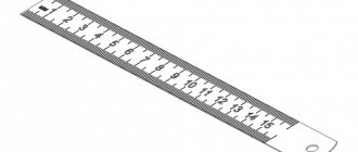
A folding meter, represented by a set of articulated rulers, is used for measurement. A meter tape differs from a tape measure by the presence of millimeter divisions. Can be placed in a blind or open box. The tape is represented by a grooved ruler that maintains straightness when unfolded.
A scale altimeter is used to measure the height of planes and holes. Includes a stand with a fixed scale equipped with a movable frame and a movable scale. It greatly simplifies markup, reducing the amount of calculations.
To construct and measure angles, a protractor is used, represented by a metal circle with degree marks and a lever with a vernier connected to its center.
Marking marking lines
In order to more accurately carry out the risk, cores are placed at its beginning and end. This allows you to visually control the position of the ruler while drawing.
On long-distance risks, auxiliary cores are also placed through
every 5-15 cm.
Circle lines are marked at four points - the ends of perpendicular diameters.
If already treated surfaces are marked, then punching is used only at the beginning and end of the marks.
After finishing, the marks are extended to the side surfaces and the cores are placed on them.
Online auction Antiquity
Online auction Antiquity
All from the ruble!
- Why register?
- How to buy?
- How to sell?
- FAQ
Basket
Sell
Registration Recent
- Lots
Sections Searches Favorites
- Lots
Sections Searches
- Recent
- Lots
- Sections
- Search
Favorites
Lots Sections Searches Buying Bargaining now I bought Didn't buy Subscribe to new lots Requests for lots from sellers Sellers' offers Selling Transactions Completed auctions Top up account Demand Seller settings My store Activation Settings
Bargaining now I bought Subscription to new lots Requests for lots from sellers Sellers' offers Selling Sell On sale Transactions Completed auctions Top up your account Demand Seller settings
| Welcome to the online auction Antiquity Use the topic sections on the left, the search bar at the top, or the tags on the right to search for items. Want to know more?
Recommended lots: (show all) 150 RUR USSR BZ small sheet Venus-Halley project 1500 RUR Vintage record Siren Grand R. Fire Moscow Kosatkin The sun rises and... Varshavsky choir 140 RUR Tractor Driver-Machinist 1st class heavy - UNC untrained 1976. price for 1 piece 030219-96 80 RUR 1969 52nd anniversary of the Great October Socialist Revolution! Kvartblok block! 4500 RUR Little ballerina Mashenka figurine fafora LFZ 12 rub. Non-standard postcard China - shops 69 RUR Kipling R. Where did armadillos come from? Fairy tale. Hood. N. Charushin. M. Baby. 1989 (B3683) 30 RUR Zarubin. Postcard. Signed. Happy holiday! March 8. Hare. Bouquet. Flowers. 100 RUR Vologda painting icon Excellent from collection No. A/2 59 RUR 2012 Guinea Personalities Paul McCartney PERFECT CONDITION 750 RUR 1946 USSR, Variation of frame shift, abklyach, 25 years of the first stamp of the USSR, hash condition. 300 RUR RUSSIA 2022 HAPPY NEW YEAR 1 SMALL SHEET (BLOCK OF 4 STAMPS) IN A FOLDER BUY! (6) | |
| 100.00 rub. | 01 minute |
| 110.00 rub. | 01 minute |
| 250.00 rub. | 01 minute |
| 300.00 rub. | 02 minutes |
| 3.00$ | 02 minutes |
| View more → |
Entrance:
| For you and your site: |
| • Auction on your website! |
| • Open your own store |
| • Affiliate program |
| Frequently asked questions and support |
| Terms of Use | Sell | Registration | Open your auction | Affiliate program | Profile | Help All rights reserved 1999 - 2022. Old man |
Applying marks
The standard regulates the procedure for drawing marking lines:
- horizontal;
- vertical;
- inclined;
- curvilinear.
Applying curved elements after straight ones provides another opportunity to check their accuracy. The arcs must close the straight lines, the interface must be smooth.
Direct marks are carried out with a well-sharpened scriber, without tearing off, in one step. At the same time, the scriber is tilted away from the ruler or square so as not to introduce distortions.
Parallel lines are drawn using a square and moving it along the reference ruler to the required distance.
Applying mutually perpendicular and parallel marks
Features of metal tools
When working with metal workpieces, a special tool is required that can be used to make in-depth markings and draw contours on a solid surface. Conventional marking does not always pay off, so the same scriber for working with metal or a bench square is made of high-strength steel grades. The same applies to calipers. The presence of wear-resistant working tips in their composition is due not only to ensuring the possibility of making markings deep into the base. Soft metals are susceptible to deformation, which causes loss of specification accuracy. For this reason, tool manufacturers use pobedite brazing and make the base from special grades of steel.
In terms of technological measurement techniques, this instrument generally corresponds to analogues intended for wood
In terms of design, a metal marking tool is almost identical to the same compasses and thickness planers, but it is important to take into account another feature. The body base in the handle part, for example, can be universal
Using different attachments, the master uses it both in operations with wood materials and in working with metal. For example, surface planers in many models can be equipped with wear-resistant metal cores.
Thread gauge
This measuring tool is used to accurately determine the thread pitch and profile. Structurally, it is a package of metal templates, each of which exactly repeats the configuration of a particular thread. Thread gauges that are designed to determine the pitch of metric threads are marked M60°, and those measuring devices that are intended to determine the number of threads per inch when measuring inch and cylindrical pipe threads are marked as D55.
Bosch Power for All
The German manufacturer also decided to assemble a series of tools for one battery.
Moreover, for household tools there are two options for battery voltage: 12 and 18 V. 12-volt battery clips are suitable for those who value the lightness and compactness of the tool. A lightweight screwdriver makes it easier to assemble furniture, install profiles under drywall and perform other finishing work. If you need to work with a more powerful and power-consuming tool, for example, a vacuum cleaner or a hammer drill, you should assemble a series for an 18-volt battery. You can choose a capacity from 2.5 to 6 Ah, taking into account what device you will work with and for how long. Garden tools such as hedge trimmers, trimmers and chain saws can also be used with these batteries. In general, the series itself and the batteries for it are somewhat more expensive than those from Ryobi, but the durability and reliability of operation pays for all costs.
Equipment and tools used
This list depends on the method of work. Manual cutting is carried out using:
- cutting tools (chisels, crosspieces, etc.);
- a plumber's hammer (chosen by weight and handle length);
- vice;
- metal substrate;
- marking tool.
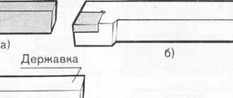
A metalworking chisel structurally consists of three main parts: impact, middle (holder) and cutting (working). The shape of the cutting part is different for each and depends on the task being solved. A chisel is used to perform a standard chopping operation. Kreuzmeisel has a narrower cutting edge. The groover is designed for cutting grooves, so its cutting part is made in the shape of a semicircle. The beard is made from a round metal rod, and has a working part in the shape of a circle sharpened around the perimeter. It is used to cut holes in sheet metal. All percussion instruments are made from durable tool steel.
The main parameters of these tools are geometric dimensions and sharpening angles of the cutting part. A plumber's hammer is used to strike the upper (impact) part of the chisel. They differ in the shape of the striker (round or square), the method of attaching the handle, and the total weight.
Cutting out small parts, holes, and individual parts is done using fastening equipment or on steel substrates. To ensure secure fastening, this operation is performed in a vice.
Various metalwork rulers, squares, marking calipers, and small markers are used as marking tools. To make marks, the following are used: cores (of various modifications), scribers with different tip shapes, and pencils. The tools used are manufactured according to developed standards
In industrial enterprises, the tools for cutting metal are special machines. These include:
- guillotines;
- presses (hydraulic and mechanical);
- press shears;
- angle cutting machines.
They have high productivity and allow you to cut even very thick metal.
The hydraulic guillotine is controlled by an electronic unit. With its help, the parameters of the future operation are set. Set the type of metal, the cutting angle, the amount of pressure on the knife, and the cutting speed. In addition to the guillotine, so-called combined units are used to solve these problems. These include cutting machines (press shears) and highly specialized ones (angle notching machines, presses and dies). Press shears are used for cutting sheets and strips of metal, shaped and long products. They work well with profile metal, for example, channel, I-roll, square. With their help, smooth holes and grooves of various shapes are obtained.
Angle notching machines allow angular cutting of metal products of almost any thickness. High precision cutting is achieved thanks to the presence of a scale that allows you to accurately lower the tool to the required place and a correctly sharpened set of chisels.
Presses and stamps solve similar problems. They use mechanical, hydraulic, pneumatic and electric drives.
Types of bench vices
In general, all vices can be divided into two groups:
- Rotary. Their mechanism is designed so that the workpiece can be rotated in the desired direction without removing it from the vice clamp. Such models are most often used on machines when drilling parts. Rotary vices often contain an anvil, due to which their strength increases and the range of actions performed expands. The anvil has different lengths and widths, depending on the vise model.
- Fixed. In such a vice, the workpiece is tightly fixed with a clamp and remains in a static position throughout the entire period of work.
A narrower gradation divides the vice by type of specialization:
- Hand-held - compact, small-sized cleats. They can be held by hand. This type of vice is used when working with small parts. There are two types of hand vices:
- Equipped with levers. These are small vices shaped like pliers with a clamp. By adjusting the clamp, which consists of two levers, you can set the width of the gap for the part held between the jaws.
Equipped with jaws that converge with each other due to the rotation of the handle. At the base of these pliers there is a special suction cup, with which the vice is easily fixed on a smooth surface and remains in a stationary position while processing a part or workpiece.
If you have to work with fragile small-sized parts, it is better to purchase cleats whose plates will be covered with a soft material, which will protect the workpiece from accidental damage when clamped tightly. The best option for such a vice is those that have the least amount of play when the jaws are set apart.
Hand bench vices can be rotary or fixed. They can simply be placed on the table, tightly fixed to its surface, or they can be attached to the side using a fastening mechanism.
- Chairs. They were so named due to the fact that they were attached to a base shaped like a chair. Now they are installed on metal workbenches. Such a vice is used when carrying out heavy work using force: when you need to bend parts, flatten or rivet something. A special feature of chair vices is the way they open the jaws. The movable plate moves away from the static one in an arc. The fixed plate is equipped with a claw for tighter fixation. Chair vices are often equipped with an anvil. The models are movable and can be rotated in the desired direction.
- Parallel. The peculiarity of this vice is that its jaws move apart evenly. The moving plate moves away from the static jaw in parallel without jumps. The size of the part that will be processed does not affect which plate will fix it.
The design of the vice is designed so that the equipment can be installed on a workbench and even on the floor. Parallel vice models can be either fixed or rotary. They can be shifted to an arbitrary angle relative to the base. This quality is considered the most convenient to use.
Free-running vise models provide reliable fixation of the workpiece. The gap between the jaws is adjusted by turning the locking knob. When the handle moves up, the movable plate is released. When the handle is lowered, on the contrary, the workpiece is fixed. You can secure it by turning the handle to the side.
What is markup
The operation of applying the dimensions and shape of a product to workpieces is called marking. The purpose of the operation is to designate the places where the part should be processed and the boundaries of these actions: drilling points, bend lines, weld lines, markings, etc.
Marks are scratched into the metal surface with a sharp tool or applied with a marker. Cores are filled with a special tool - a center punch.
According to the method of execution, there are such types of markup as:
- Manual. It is made by mechanics.
- Mechanized. Performed using mechanization and automation tools.
Based on the application surface, they are distinguished
- Superficial. It is applied to the surface of the workpiece in one plane and is not associated with the lines and marking points applied to other planes.
- Spatial. It is carried out in a unified three-dimensional coordinate system.
Notes on straightening and marking for thin sheet metal
The choice between surface and spatial markings is determined, first of all, by the complexity of the spatial configuration of the part.
Techniques
Markings, marking tools and fixtures are used in several different ways for a variety of tasks.
If woodworking allows you to use not only scratching scribers, but pencils, felt-tip pens, and even chalk, then when making elements from metals, it is preferable to apply marks with sharp instruments. This is due to the fact that precision is required within the limits of the thickness of the strip.
Welding work in most cases allows planning with a marker, since in the process of joining the workpieces the gap is filled with a seam.
Marking straight lines
Despite the apparent simplicity of such a task, there are quite a lot of nuances and in some cases they are significant. For example, a slight misalignment of the thicknesser narrows the line; therefore, when drawing parallel guides, it is necessary to hold the tool correctly, strictly perpendicular to the edge. The error increases when marking such features that are located at a great distance from each other.
In many cases you have to use a ruler. The most common mistake here is deflection and deviation from the plane. The scratch will not be applied correctly.
There is another way - using fixation with a clamp or temporary welding. In carpentry, a thread with a chalk surface was used to form the direction of the work. Of course, the thickness turns out to be decent, but when marking logs, such an operation is permissible.
One of the modern devices is a laser. It leaves a clear visible line. All we have to do is fix it with a scriber or pencil.
What tools should be used when marking circles and devices for this process
Forming a pattern in the form of a circle is done with a compass. This works well for parts ranging in size from a few centimeters to a meter. Small holes are easier to apply using a pattern. Large radii will have to be created by creating a special analogue. In many cases it is necessary to make the center with a core or drill. If damage is unacceptable, then use a suction cup, for example, when cutting glass.
In mass production, it would be most correct to use a template made for a specific workpiece. Here, not only evenness is taken into account, but also the positioning of the lines relative to each other.
It is often necessary to draw an oval (ellipse). In this case, a cord is taken, two centers are fixed and a sharp object is drawn around two points. The sum of the distances between the three source data is always constant. This is achieved by using a measured section of cord.
Planar marking Plumbing
Planar marking can be done by direct drawing, using a template (which consists of placing a template on the part to be marked and drawing on it, followed by marking the contours of the lines) and using a template that is used as a template.
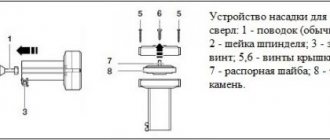
Example 1. Marking the lock washer for the adapter sleeves for ball bearings.
2. Clean one of the planes and seal the marking areas.
3. Draw two center lines at right angles to one another. Mark the center.
4. From the center, using a compass solution, draw three circles with radii 15.5 onto the given circles; 19.5 and 25 mm.
5. Construct central angles.
6. Mark the external splines.
7. Mark the internal slot.
8. Mark the contours of the washer.
Example 2. Marking a keyway on a shaft.
1. Clean the marked areas on the roller.
2. Paint the end of the roller and the part of the side surface on which the marks will be made with vitriol.
3. Find the center at the end using a center finder.
4. Place the roller on the prism and check its horizontalness.
5. Apply a horizontal line passing through the center at the end of the roller using a thickness gauge.
6. Turn the roller 90° and check the verticality of the drawn line against the square.
7. Draw a horizontal line on the end of the roller using a thickness gauge.
8. Draw a line on the side surface of the roller with a thickness gauge.
9. Draw two lines on the side surface corresponding to the width of the keyway, and on the end - approximately to the depth of the groove.
10. Turn the shaft with the key marks upward and draw a line for the depth of the keyway at the end.
11. Mark the contours of the keyway.
Bosch Power for All
The German manufacturer also decided to assemble a series of tools for one battery. Moreover, for household tools there are two options for battery voltage: 12 and 18 V. 12-volt battery clips are suitable for those who value the lightness and compactness of the tool. A lightweight screwdriver makes it easier to assemble furniture, install profiles under drywall and perform other finishing work.
If you need to work with a more powerful and power-consuming tool, for example, a vacuum cleaner or a hammer drill, you should assemble a series for an 18-volt battery. You can choose a capacity from 2.5 to 6 Ah, taking into account what device you will work with and for how long. Garden tools such as hedge trimmers, trimmers and chain saws can also be used with these batteries. In general, the series itself and the batteries for it are somewhat more expensive than those from Ryobi, but the durability and reliability of operation pays for all costs.
Dial indicator
This measuring instrument is a device where very small movements made by the measuring probe are converted into angular movements of the arrow. Dial indicators are used when it is necessary to determine with a significant degree of accuracy those deviations that a certain part has in its geometric shape in relation to the specified parameters. In addition, these devices are used to control the relative position of surfaces.
General provisions
Locksmith work refers to the assembly and repair of all kinds of components, processing of materials (steel and metal alloys) in a variety of sectors of the national economy: mechanical engineering, consumer services (lock repair, etc.), after-sales service and car repair. Accordingly, there are different types of locksmith work.
A locksmith's workplace can look different. In general, this is a certain area of the workshop (site), equipped with all the necessary equipment and tools. Types of locksmith work can vary greatly from each other. Therefore, in one case the workplace is a desk in a warm and cozy room, in the other it is a tent without amenities somewhere in the taiga (during the construction and repair of gas and oil pipeline infrastructure).
The most common and universally recognizable tool of a mechanic is the workbench. This is, in fact, a table on which there are all the necessary tools for carrying out technological operations assigned to a given workplace. There must also be a device for securing working drawings of products.
As a rule, the tabletop itself is made of hardwood and covered with sheet steel one millimeter thick. It is advisable to equip drawers under the table for storing tools and materials. The absence of a protective metal screen on a workbench is considered a gross violation of labor safety standards and regulations.
Tickets and answers for the training program for mechanics 2-3 categories
Questions and answers on the training program for mechanics of 2-3 categories are intended to test the knowledge of the level of training of personnel in production
The safety questions encountered correspond to the general course on industrial safety.
1. Marking, its types and purpose
Marking is the operation of applying lines and dots to a workpiece intended for processing. Lines and dots indicate processing boundaries.
There are two types of markings: flat and spatial. Marking is called flat when lines and points are applied to a plane, spatial – when marking lines and points are applied to a geometric body of any configuration.
Spatial markings can be made on a marking plate using a marking box, prisms and squares. When marking in space, prisms are used to rotate the workpiece being marked.
2. Tools and devices for marking, types and their purpose
For flat and spatial marking, a drawing of the part and a workpiece for it, a marking plate, a marking tool and universal marking devices, a measuring tool and auxiliary materials are required.
Marking tools include: scriber (with one point, with a ring, double-sided with a curved end), marker (several types), marking compass, punches (regular, automatic for stencil, for circle), calipers with a conical mandrel, hammer, center compass , rectangle, marker with prism.
Marking devices include: a marking plate, a marking box, marking squares and bars, a stand, a thicknesser with a scriber, a thicknesser with a moving scale, a centering device, a dividing head and a universal marking grip, a rotating magnetic plate, double clamps, adjustable wedges, prisms , screw supports. Measuring tools for marking are: a ruler with divisions, a thickness gauge, a thickness gauge with a moving scale, a caliper, a square, a protractor, a caliper, a level, a control ruler for surfaces, a feeler gauge and standard tiles.
Auxiliary materials for marking include: chalk, white paint (a mixture of chalk diluted in water with linseed oil and the addition of a composition that prevents the oil from drying out), red paint (a mixture of shellac with alcohol with the addition of dye), lubricant, washing and etching materials, wooden blocks and slats, a small tin container for paints and a brush.
Simple marking and measuring tools used in plumbing work are: a hammer, a scriber, a marker, an ordinary center punch, a square, a compass, a marking plate, a graduated ruler, a caliper and a caliper.
3. The process of planar marking, determining the order of marking, the method of execution, checking the marking and core punching of parts.
Planar or spatial marking of the part is carried out on the basis of the drawing.
Before marking, the workpiece must undergo mandatory preparation, which includes the following operations: cleaning the part from dirt and corrosion (do not do it on a marking plate); degreasing the part (do not do it on a marking plate); inspection of the part in order to detect defects (cracks, cavities, bends); checking overall dimensions and processing allowances; determination of the marking base; covering with white paint the surfaces to be marked and lines and dots applied to them; determination of the axis of symmetry.
If a hole is taken as a marking base, then a wooden plug should be inserted into it. A marking base is a specific point, axis of symmetry or plane from which, as a rule, all dimensions on a part are measured. Penciling is the operation of applying small dots-indentations on the surface of a part. They define the centerlines and hole centers required for machining, certain straight or curved lines on the product. The purpose of marking is to mark persistent and noticeable marks on the part that define the base, processing boundaries or drilling location. The punching operation is performed using a scriber, a center punch and a hammer.
4. Marking according to templates, marking accuracy
Marking using a template is used in the manufacture of a significant number of identical parts. A template made of tin 0.5–2 mm thick (sometimes stiffened with a corner or wooden strip) is placed on the flat surface of the part and traced along the contour with a scriber. The accuracy of the applied contour on the part depends on the degree of accuracy of the template, the symmetry of the scriber's tip, as well as on the method of advancing the scriber's tip (the tip must move perpendicular to the surface of the part). The template is a mirror image of the configuration of parts, lines and points that must be applied to the surface of the part.
The accuracy of marking (the accuracy of transferring dimensions from the drawing to the part) depends on the degree of accuracy of the marking plate, auxiliary devices (squares and marking boxes), measuring instruments, the tool used to transfer dimensions, on the degree of accuracy of the marking method, as well as on the qualifications of the marker. The marking accuracy is usually from 0.5 to 0.08 mm; when using standard tiles - from 0.05 to 0.02 mm.
5. Safety precautions when marking
6. Metal cutting, cutting tools.
The material to be cut (tin plate, strip iron, steel strip, profile, rod) should be placed on a steel plate or anvil so that its entire surface is adjacent to the surface of the plate or anvil. The material from which the workpiece needs to be cut can be secured in a vice. If the metal is longer than the plate or anvil, its overhanging end should be supported by suitable supports.
A sheet or piece of tin with the outline of the element marked on it is placed on a steel plate to cut the tin. The tip of the chisel is placed at a distance of 1–2 mm from the marked line. By hitting a chisel with a hammer, the tin is cut. By moving the chisel along the contour and, at the same time, hitting it with a hammer, they cut out the shaped element along the contour and separate it from the sheet of tin.
Cutting out an element from a thick sheet material is performed first on one side of the sheet, then it is turned over to the other side and finally cut out (by moving the chisel along the resulting mark from the tip of the chisel). The cut element along the contour is processed with a hand file.
Before marking, bent or dented sheet metal should be straightened on the plate with a rubber or wooden hammer. Before laying the sheet on the slab during straightening, marking and cutting, the slab should be thoroughly cleaned and wiped. The tin must adhere to the slab with its entire surface. Do not use a dull or chipped chisel or a chipped or chipped hammer.
When cutting viscous materials (thick tin or strip iron), in order to protect the chisel from jamming, the cutting part of the chisel should be lubricated with oil or water and soap, which reduces friction and makes it possible to obtain a smooth cut surface.
A chisel is used to cut material in cases where it is difficult or impossible to use scissors or a saw due to the complexity of the required configuration of the part, when the necessary scissors are not available (generally or at the moment), when the material being cut is too hard.
A chisel is used for cutting, and a crossmeisel is used for cutting.
7. Design, dimensions and sharpening angles of chisels and kleitzmeisel
A bench chisel is a tool made of tool carbon steel U7A or U8A with a rectangular or rounded profile, one end of which has a wedge shape. Chisel dimensions: length 100–200 mm, thickness 8–20 mm, width 12–30 mm. A metalworking chisel is used for chopping or removing a layer of metal when precision processing is not required. It can also be used to cut, trim and trim material.
Depending on the type of material being cut or trimmed, the sharpening angle of the chisel is: 60° for steel, 70° for cast iron and bronze, 45° for copper and brass, 35° for zinc and aluminum.
A crossmeisel is a metalworking tool that is similar to a chisel, but has a narrow or shaped (groove) cutting part. It is used for cutting rectangular or shaped grooves. Made from tool carbon steel U7A or U8A. Crossmeisel dimensions: length 150–200 mm, width 12–25 mm, thickness 8–16 mm; groover dimensions: length 80-350 mm, width 6-25 mm, thickness 6-16 mm.
There are several types of crossbars: rectangular, semicircular and special
Carving is the process of making grooves, recesses, and also auxiliary grooves using a crossmeisel when cutting a large surface.
8. Safety precautions when cutting metals
9. Straightening and bending of metals
Straightening is the operation of returning crooked or bent metal products to their original straight or other shape. Straightening is done hot or cold manually, as well as using devices or machines.
Most often, wire, hot-rolled or cold-drawn rods, strip and sheet metal are straightened. Sectional metal (angles, channels, T-beams, I-beams and rails) undergoes editing less frequently.
A material or product made of non-ferrous metals should be adjusted taking into account its physical and mechanical properties with a hammer made of the appropriate metal. Hammers made of the following non-ferrous metals are used: copper, lead, aluminum or brass, as well as wooden and rubber hammers.
Flexible is the operation of giving metal a certain configuration without changing its cross-section and processing the metal by cutting. Bending is done cold or hot manually or using devices and machines. Bending can be done in a vice or on an anvil. Bending metal and shaping it can be facilitated by the use of templates, core molds, bending dies and fixtures. Bending a large number of metal rods to give them a certain shape is possible only in specially designed and manufactured dies and bending equipment for this purpose.
10. Tools and devices for straightening/bending metal
For straightening shaped, sheet and strip metal, various types of hammers, plates, anvils, rolls (for straightening tin), manual screw presses, hydraulic presses, roll devices and gates are used.
Bending of metal depending on its thickness, configuration or diameter is done with a hammer using metal tongs or blacksmith's tongs on a straightening plate, in a vice or in molds or on an anvil. You can also bend metal in various bending fixtures, bending machines, press brake dies, and other equipment.
11. Pipe bending
Pipe bending can be done hot or cold using special templates or rollers using bending devices (Fig. 12) or pipe bending machines.
Thick-walled pipes with a diameter of no more than 25 mm and a bending radius of more than 30 mm can be bent in a cold state without filling them with dry fine sand, lead, rosin and without inserting a coil spring into them. Pipes of large diameters (depending on the wall thickness and the grade of metal from which the pipe is made) are bent, as a rule, by heating the bending point and filling the pipe with the appropriate material. In this case, the ends of the pipe are plugged with plugs, which reduces the possibility of its breakage or flattening during bending. Pipes with a seam should be bent in such a position that the bending force is applied in a plane perpendicular to the seam.
12. Safety precautions when straightening and bending
13. Cutting and sawing metal, tools for cutting and sawing
Cutting is the operation of dividing a material (object) into two separate parts using hand scissors, a chisel or special mechanical shears. Sawing is the operation of separating a material (object) using a manual or mechanical hacksaw or circular saw.
The simplest tool for cutting metal is ordinary hand scissors, right and left (the upper cutting edge can be to the right or left of the lower cutting edge).
Scissors can be hand-held or stationary, mounted on a workbench. Mechanical devices and equipment include vibrating shears and machines, lever mechanical shears, and guillotine shears and presses. Cutting of sheet material, especially cutting of shaped parts, is carried out with a gas acetylene-oxygen torch, and in some cases - on milling machines with finger and other special cutters. Cutting of bar material can be done on lathes using cutting tools. Pipe cutting is done with special pipe cutters. For sawing materials, manual and mechanical hacksaws with a permanent or sliding frame, band saws, circular saws and other mechanisms are used.
14. Metal filing, filing allowance
Filing is the process of removing stock using files, needle files or rasps. It is based on manual or mechanical removal of a thin layer of material from the surface being treated. Filing is one of the main and most common operations. It makes it possible to obtain the final dimensions and the required surface roughness of the product.
Filing can be done with files, needle files or rasps. Files are divided into the following types: metalworking files for general purposes, metalworking files for special work, machine files, for sharpening tools and for hardness control.
15. Files, types and purpose
Files are made from high-carbon tool steel U12A, U13A, as well as steel grades P9, P7T, ShKh9, 111X15.
File teeth can be formed by notching, milling, tapping, broaching, and rolling turning. The most common method is cutting. The cut of files for general purpose is double cross, and for files for special work it is double and single. Thanks to the cross notch on the surface being filed, there are no marks from traces of tooth movement. The teeth are cut on the workpieces before they are heat treated. After cutting, the files are hardened to a hardness of at least HRC 54.
When repairing worn files, the surface of the files is tempered and ground before applying the notch. All files must be tested.
Depending on the shape, the following types of files are distinguished (Fig. 19): a – metalworker’s flat, blunt-nosed files; b – round; c – semicircular, d – square; d – triangular; e – flat pointed-nosed; g – hacksaws; h – oval; and – lens; k – rhombic; l – semicircular wide; g – rasps, n – for filing machines; o - for soft metals, as well as curved files.
According to the size and density of the notches, depending on the number of notches per 10 mm of length, the files are divided into basal files No. 0 and 1, personal files No. 2 and 3 and velvet files No. 4 and 5. Brussels file No. 0 has the coarsest notch. With a garnish file length of 100 mm, the number of notches per 10 mm length is 14, while velvet file No. 5 has a very fine notch - 56 notches per 10 mm with the same file length.
16. Filing of various surfaces of parts
The following types of filing are distinguished: flat and curved surfaces; corner surfaces; parallel surfaces; complex and shaped surfaces.
The choice of file depends on the type of material, the type of filing, the size of the layer being removed and the size of the workpiece. For example, when finishing a cube made of steel with an edge length of 30 mm, you need to use a file with a double cut No. 5 (velvet) 160 mm long.
The shape of the files is chosen depending on the configuration of the area being treated. Flat files are used for filing flat, curved convex and outer spherical surfaces; square files – for filing square and rectangular holes; triangular - for processing triangular surfaces, for sharpening saws, as well as for filing flat surfaces located at an acute angle; hacksaws - for filing the edges of sharp corners, as well as for making narrow grooves; rhombic - for processing very complex contours of products; round – for making semicircular and round holes; oval – for filing oval holes; semicircular and lens - for processing curved and concave surfaces.
17. Safety precautions when filing
18. Drilling, countersinking, reaming holes
Drilling is the making of a round hole in a product or material using a special cutting tool - a drill, which during the drilling process simultaneously has a rotational and translational movement along the axis of the hole being drilled. Drilling is used primarily when making holes in parts that are connected during assembly.
Countersinking is an increase in the diameter of a previously drilled hole or the creation of additional surfaces. For this operation, countersinks are used, the cutting part of which has a cylindrical, conical, end or shaped surface.
The purpose of countersinking is to create adequate seats in holes for the heads of rivets, screws or bolts or to align end surfaces.
Reaming gives the final hole size required by the drawing. The diameter of the hole for reaming must be less than the final one by the amount of allowance for reaming
19. Tools and devices used for drilling
Mechanically driven drilling machines include vertical drilling machines, radial drilling machines, horizontal boring machines and special drilling machines. Vertical drilling machines may have devices for using multi-spindle heads. Special drilling machines can be modular, multi-position and multi-spindle. The following operations can be performed on drilling machines: drilling, reaming a previously drilled hole to a larger diameter, countersinking, reaming, facing, countersinking, countersinking, threading.
To perform the drilling operation, drills with a conical or cylindrical shank, conical adapter bushings, wedges for knocking out drills, self-centering drill chucks with two and three jaws, handles for fastening drills in chucks, quick-release chucks, spring chucks with automatic shutdown of the drill, machine vices, boxes are used. , prisms, clamps, squares, hand vices, inclined tables, as well as various types of devices, manual and mechanical drilling machines and drills.
20. Drill design
A drill is a cutting tool used to make cylindrical holes.
According to the design of the cutting part, drills are divided into feather drills, with straight flutes, spiral drills with helical flutes, for deep drilling, centering and special. Depending on their design, twist drills are divided into twisted, milled, cast (for large diameters), with plates made of metal carbide alloys and welded.
Drills are made from tool carbon steel U10A, U12A, alloy steel 9ХС or from high-speed steel R18, R9, REM. Drills lined with tungsten and titanium carbide alloy plates are often used.
A twist drill is used to make holes that have high precision requirements, holes intended for further processing by reaming, boring or pulling, holes for threading.
A twist drill consists of a shank and a working part, which is divided into a guide and cutting parts. There is a neck between the guide part and the shank.
The shank is a part of a drill of a cylindrical or conical shape (wood drills have a tetrahedral conical shank), which serves to secure the drill in a conical shape in conical adapter sleeves with a Morse taper, and in a cylindrical shape in a two- or three-jaw drill chuck. Tapered shanks end with a foot, which serves to knock the drill out of the spindle or tapered adapter sleeve. The cylindrical shank ends with a leash. Drills with a cylindrical shank usually have small diameters (up to 20–30 mm).
The working part of the drill consists of a guide and cutting parts. The guide part of the drill is the part located between the neck and the cutting part. It serves to guide the drill along the axis of the hole. The guide part has helical grooves for removing chips and a drill rod. There is a ribbon on the outer screw surface of the drill guide.
The cutting part of a twist drill consists of two cutting edges connected by a third edge - the so-called transverse bridge. A ribbon is a narrow belt along a helical groove that smoothly runs down to the shank. The purpose of the tape is to absorb part of the friction of the drill against the walls of the hole that appears as the tool enters the material. The diameter of the drill is measured by the distance between the strips.
To go to another page, use the navigation below
Page: 1