TO
category:
Turning
Cutting tools of lathes
Next: Inspection Tool
For the manufacture of cutting tools, the following tool materials are used (Fig. 92): carbon, alloy, high-speed steels; hard alloys; mineral ceramics; artificial diamonds; synthetic materials (composites, hexomites), etc.
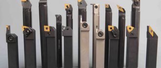
Incisors. The most common type of cutting tool used on lathes is cutters. According to their design, the incisors are divided into straight right and left and bent (Fig. 93). To determine the direction of the cutting edge of the cutter, place your palm on its surface so that your fingers are directed towards the top of the cutter. A left cutter is called a cutter whose main cutting edge will be on the side of the thumb of the left hand (Fig. 94, a), and a right cutter, the cutting edge of which will be on the side of the thumb of the right hand (Fig. 94, b). The right and left bent incisors are shown in Fig. 94, v.
Rice. 93. Solid (a), brazed (b) and assembled (c) cutters
Rice. 94. Types of incisors
Rice. 95. Powers of chisels
Rice. 96. Fastening multi-faceted cutting inserts
Rice. 98. Fastening of replaceable multifaceted plates with a clamp and a screw with multidirectional threads
Rice. 99. Attaching interchangeable polyhedral plates with an L-shaped lever and screw
The cutter holders can be rectangular (Fig. 95, a), square {Fig. 95, b) and round (Fig. 95, c). Multifaceted cutter plates are attached from above (Fig. 96, a), with a clamp and through the hole (Fig. 96.6), through the hole (Fig. 96, c), with a screw through the hole (Fig. 96, d).
According to their purpose, the incisors (Fig. 97) are divided into 1 - pass-through; 2 — bent through passages; 3 - cutting; 4 - cutting; 5 - boring; 6 - groove; 7 - threaded; 8— shaped; 9 - shaped vibration dampers.
Multifaceted replaceable plates are secured with a clamp (Fig. 98) and a screw 3 with multidirectional threads, plates (Fig. 99) with a hole - an L-shaped lever and a screw, plates with a shaped hole - a screw (Fig. 100), plates with a hole - a wedge - clamp and screw (Fig. 101), plates with a hole - pin and ball (Fig. 102), plates - clamp and screw (Fig. 103).
The front surface (Fig. 104) is: 1 - flat with a positive front angle; 2 - flat with a negative chamfer; 3—flat with a negative chamfer and a soldered chip breaker; 4 - curved with a negative chamfer;
Rice. 100. Fastening of replaceable polyhedral plates with a shaped hole with a screw (a) with a support plate (b) and without a support plate (c)
Rice. 101. Fastening of replaceable polyhedral plates with a hole and a clamp and a screw
Rice. 102. Fastening of replaceable polyhedral plates with a hole with a pin and a ball
Rice. 103. Fastening stepped plates with clamps and screws
Rice. 104. Shape of the front surface of the cutter
Rice. 105. Cutters equipped with plates made of super-hard composite materials
Cutters equipped with plates made of superhard composite materials (Fig. 105) are a qualitatively new group of tools that allow processing at high cutting speeds. The plates are produced in round, rhombic, square and triangular shapes.
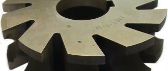
Drills are cutting tools consisting of a working part and a shank (Fig. 106). They are made with a diameter of 0.1 to 80 mm and are used to form carbide plates (5).
Rice. 106. Twist drill with a cylindrical (a) and ionic (b) shank: a - clearance angle; f is the angle of inclination of the transverse edge; y—front corner; “—angle of inclination of helical grooves; 2(0 - vertex angle
Rice. 107. Types of drills
Rice. 108. Types of twist drills
Rice. 109. Countersink: D-outer diameter; d-inner diameter; z-number of teeth; <р – angle of the cutting part; w-angle nylon screw grooves; f-belt width
Rice. 110. Zenkovni
Rice. 111. Examples of using countersinks: 1— body; 2 - replaceable burdens; 3 - holes; 4 - adjustable countersinks
Rice. 112. Sweeps
Reamers with cylindrical (Fig. 112, a) and conical (Fig. 112,6) shanks are designed for finishing machining of through and blind holes. According to their design, reamers are divided into solid and composite with cylindrical and conical shanks, mounted. According to their purpose, reamers can be manual or machine. According to the shape of the working part, they are divided into cylindrical (Fig. 113, a-d) and conical (Fig. 113, e). The chip flutes of the reamer can be straight or helical. Reamers can be one-piece with soldered plates (Fig. 113, f) and detachable with insert knives (Fig. 113, g, h).
Rice. 113. Sweeps
Rice. 114. Structural elements of the tap
Rice. 115. Types of marks
In addition to reamers that have a constant diameter and serve to process holes of the same diameter, expanding and adjustable reamers are used (Fig. 113, i, j, l).
Taps and dies. Taps are cutting tools designed for the formation and processing of internal cylindrical and tapered threads (Fig. 114). They have a conical intake part 1 and a calibrating part 2, chip flutes and a square shank. The front surface of the tap tooth is a plane that smoothly mates with the bottom of the chip flute. The back surface of the tooth can be backed or not backed, when the back surface is cylindrical. The main cutting edge, cutting the chips, is inclined to the axis of the tap at an angle cf. The auxiliary cutting edge 8 forms the thread profile. For cutting metric threads (Fig. 115, a) with a pitch of 3 mm, a set of two taps / and // is used, for threads with a pitch of ^3 mm - a set of three taps I-III.
According to their purpose, taps are divided into hand taps (Fig. 115.6), machine taps with straight or helical grooves, machine-hand taps right and left for cutting metric and inch threads, conical taps for cutting tapered threads. In Fig. 116 shows straight nut taps for cutting threads in nuts, curved nut taps for cutting threads in nuts on automatic machines. To cut threads in blind holes, taps with a short chamfer are used; for cutting threads in through holes - taps with a long chamfer.
According to the thread profile, taps are divided into taps with metric threads with a profile angle of 60° and taps with inch threads with a profile angle of 55° (Fig. 117). The design of a chipless tap is shown in Fig. 118.
Round dies (Fig. 119) are designed for the formation and processing of external cylindrical and tapered threads. Structurally, round dies consist of a ring with cutting edges and holes for chip exit. Dies come with metric 4 and inch 5 threads, solid and split. The wear of the axial and thread-forming tools is indicated in the appendix.
Rice. 116. Varieties of tap shanks
Rice. 117. Threads for cutting metric and inch threads
Rice. 118. Design of a chipless tap
Rice. 119. Round dies
Threading heads are used for cutting external and internal threads. They come with round combs, non-rotating (Fig. 120, a) and rotating (Fig. 120.6); with tangential flat combs (Fig. 120,c); for internal thread (Fig. 120, d); tangential (Fig. 120, d). External threads are rolled using thread rollers (Fig. 120, e). The shank is mounted in a longitudinal movement support.
The thread rolling head rolls threads with two rollers that rotate on two axes mounted on levers that rotate around a central axis. The center-to-center distance of the thread rolling rollers is adjusted with screws. The plunger and thrust bolt are used to select the side clearances in the gear transmission of the head.
Tool wear. During the cutting process, as a result of friction, the tool wears out on both the front and rear surfaces. With finishing machining and a chip thickness of 0.1 mm and an average cutting speed - along the front and rear surfaces (Fig. 121.6). At high cutting speeds and chip thickness >0.1 mm, the tool wears out where the edge of the crater merges with the worn rear surface (Fig. 121, c).
Rice. 120. Non-rotating and rotating heads for threading
Tools are sharpened at tool manufacturing plants. During operation, after reaching a critical wear value, the tool is sharpened again. Drills are sharpened along the back surface (Fig. 122).
The type of sharpening and the shape of the point are shown in Fig. 123, a...g.
Rice. 121. Types of wear of cutting tools
Rice. 122. Sharpening the drill
Rice. 123. Point shape of twist drills:
The sharpening of drills is controlled using templates and protractors (Fig. 124).
The cutters are sharpened on both the back and front surfaces (Fig. 125). If the main cutting edge 2 (Fig. 126, a) is sharpened obliquely downwards relative to the top /, when processing a workpiece made of soft and tough metal, chips 3 are directed towards the surface being processed. The main cutting edge 2 (Fig. 126, b) is sharpened horizontally relative to the top 1. When processing a workpiece made of medium-hard materials, chipping chips are formed. If the main cutting edge 2 is sharpened obliquely upward relative to the top 1 (Fig. 126, c), the chips 3 are directed towards the machined surface.
To sharpen cutters, sharpeners and specialized machines ZD642E and ZA641E are mainly used. The chamfers and the top of the cutter head 1 (Fig. 127, a) are adjusted manually with a fine-grained carborundum or diamond stone 2. After sharpening, the cutters are checked with a template and an inclinometer (Fig. 127,6).
Rice. 124. Control of sharpening drills with a complex template and protractor: a—the angle at the tip and the length of the cutting edges; b—point angle; c—the angle between the transverse and cutting edges; z-angle of inclination of the cutting edge
Rice. 125. Sharpening the cutter along the main back (a), auxiliary back (b), front surface (c) and the radius of curvature of the tip of the cutter (d)
Reamers are sharpened and adjusted along the front surface while basing them in the centers. The quality of sharpening of the reamer teeth is controlled using templates and devices with dial indicators.
The taps are sharpened along the front surface while basing it in the centers. To sharpen taps, use a device that fixes the position of the tap with a stop. To control taps, they cut a thread and then control it with thread gauges. Round dies are sharpened on special MF-4A machines (Fig. 130). To check the quality of manufacture of the dies, a thread is cut on a control screw, then the thread is checked with thread gauges.
How to choose the right turning cutting tool
Turning cutting tools can machine virtually any type of surface. Depending on the holder used, it is possible to produce a part either cylindrical or with a shaped surface. When choosing a tool for metalworking, you should pay attention to many factors that determine their quality. Thus, reliable equipment cannot be cheap. If you choose between price and quality, it is better to bet on the latter aspect, but of course you have to pay for quality. But it should be understood that a good cutting unit will last much longer and will save money overall.
Particular attention should be paid to the material of the cutting part. Currently, the vast majority prefer to choose products made from hard alloys, which, along with wear resistance, allow you to work with almost any metal.
An important detail is the cutting edges. They must be durable, since durability during processing of the part depends on this. With rapid wear of the cutting edge, it is necessary to change equipment more often, and this leads to an increase in the cost of processing and, accordingly, the cost of the product.
Depending on the metal being processed, one or another type of hard alloy from which the cutting part is made and cutting modes are selected. High speed steel is only suitable for low speed work and soft materials. But products made of hard alloy, mineral ceramics or cubic boron nitride have a high level of wear resistance and allow you to work with a high level of productivity.
Turning tool accessories, service life
If you decide to purchase a turning tool, then you should think in advance about what additional equipment you need. The fact is that due to high operating speeds, even the most expensive equipment will not be able to work efficiently if the equipment lags behind, so it is necessary to acquire a holder. They help keep it in a fixed position, which has a positive effect on work results. If you need to make a precise cut, you must be sure that the tool will not slip - the holder will help ensure this. It is attached directly to the machine. Many holders have several holes at once, which will allow you to change attachments directly during operation, which will significantly speed up the process. You can also select holders with adjustable locking, allowing you to vary the supported turning tool within a given range. This again will allow you to save on equipment by buying one product instead of one.
Areas of use
We looked at what cutting tools there are, but where and when are they in demand? They are virtually indispensable in all major industries, but they can only be used effectively if certain requirements are met:
- the material they are made must be harder and stronger than the metal they process;
- the workpiece must be securely fastened;
- It is necessary to strictly observe safety precautions and the parts production scheme.
If all these conditions are met, you can count on long-term and cost-effective operation.
Another important niche is small private and home workshops. They require manual devices - all kinds of machines and machines designed for piece operations, at low speeds and with low feeds.
Why do we need metal turning tools, and what are they?
Today, metal turning tools are widely used in the production and manufacture of various parts and mechanisms when processing bodies of rotation. At the same time, the variety of technical solutions in the field of turning cutting tools is enormous. There are several groups:
- neutral, right or left (determine the cutting direction);
- according to material - from quick cutter or hard alloy;
- solid or composite, consisting of several elements.
The above classification demonstrates only a small part of the differences in design. And although they all differ from each other in functional purpose, they also have some common features.
How to choose the right turning cutting tool
Turning cutting tools can machine virtually any type of surface. Depending on the holder used, it is possible to produce a part either cylindrical or with a shaped surface. When choosing a tool for metalworking, you should pay attention to many factors that determine their quality. Thus, reliable equipment cannot be cheap. If you choose between price and quality, it is better to bet on the latter aspect, but of course you have to pay for quality. But it should be understood that a good cutting unit will last much longer and will save money overall.
Particular attention should be paid to the material of the cutting part. Currently, the vast majority prefer to choose products made from hard alloys, which, along with wear resistance, allow you to work with almost any metal.
An important detail is the cutting edges. They must be durable, since durability during processing of the part depends on this. With rapid wear of the cutting edge, it is necessary to change equipment more often, and this leads to an increase in the cost of processing and, accordingly, the cost of the product.
Depending on the metal being processed, one or another type of carbide is selected from which the cutting part of the metal turning tool is made, and cutting modes. High speed steel is only suitable for low speed work and soft materials. But products made of hard alloy, mineral ceramics or cubic boron nitride have a high level of wear resistance and allow you to work with a high level of productivity.
Turning tool accessories, service life
If you decide to purchase a turning tool, then you should think in advance about what additional equipment you need. The fact is that due to high operating speeds, even the most expensive equipment will not be able to work efficiently if the equipment lags behind, so it is necessary to acquire a holder. They help keep it in a fixed position, which has a positive effect on work results. If you need to make a precise cut, you must be sure that the turning cutting tool will not slip - this will help ensure the holder. It is attached directly to the machine. Many holders have several holes at once, which will allow you to change attachments directly during operation, which will significantly speed up the process. You can also select holders with adjustable locking, allowing you to vary the supported turning tool within a given range. This again will allow you to save on equipment by buying one product instead of one.
Classification of metal-cutting tools
There are a number of key parameters - let's take a look at each.
Based on the nature of processing (action), they are divided into:
- blade - cut off excess material;
- abrasive - abrade the surface, bringing it to the desired geometry by grinding.
By design they can be:
- solid - completely made from one piece;
- composite - made of several parts, all connections of which are permanent;
- prefabricated - their elements are fastened so that they are easy to separate if necessary.
According to the mounting option, there are top-mounted and tail-mounted ones. There are also options for drives (manual, machine or combined) and shape (plate, cylindrical, disk, conical), and each of them is in demand in its niche.
Where can I buy metal turning tools?
The best prices for goods and we guarantee their quality. If you are going to buy a turning cutting tool, then you should pay attention to the following factors:
- price;
- reputation of the manufacturer;
- quality;
- range.
On our website you can purchase turning tools from the most famous manufacturers. We guarantee a high level of product reliability. Another convenient advantage is the fact that we deliver to the consumer’s warehouse. We offer a wide selection of turning cutting tools with an optimal price-quality ratio.
Geometry of turning tools
Image: geometry of a turning tool.
Let's talk about the angles of the incisors and their purposes.
- Back auxiliary angle (α1). As it decreases, the friction force between the rear plane of the tool and the workpiece decreases.
- Apex angle (ε). Formed between the cutting edge and the rear auxiliary plane. The larger this angle, the better the heat removal conditions and the higher the strength of the cutter.
- Auxiliary plan angle (ϕ1). Its size varies from 10 to 30°. As the angle decreases, the cleanliness of the treatment improves, but the friction force increases.
- Leading angle (ϕ). Its size varies from 20 to 90°. The length and width of the cut depend on the size of the angle. The smaller ϕ, the lower the temperature and cutting force. The cleanliness of the processing is also improved. But as the angle decreases, vibration and radial cutting force increase.
- Cutting angle (δ). Formed between the rake surface and the cutting plane.
- Basic rake angle (γ). Its size varies from -5 to +15°. As the angle increases, it is easier for the tool to cut into the metal, chip removal is improved, and the cutting force, deformation of the machined surface, and power consumption are reduced. However, this reduces heat dissipation and reduces the service life of the cutting edge.
- Taper angle (β). Formed between the front and main back surfaces. Affects the sharpness and strength of the tool.
- Main relief angle (α). Its size varies from 6 to 12°. As the angle decreases, the friction force between the part and the back surface of the cutter decreases. This improves heat dissipation and extends the service life of the tool, but the cleanliness of the machined surface deteriorates.
- Angle of inclination of the main cutting edge (λ). Affects the direction of chip removal. At positive λ and λ = 0°, the chips move towards the machined surface. Cutters with positive λ (12–15°) are used when processing workpieces made of heat-resistant and hardened steels. For universal turning tools, λ = 0°. Cutters with negative λ are used for finishing.
Milling and grinding accessories
In modern metalworking, devices for milling the surface of the workpiece are widely used. With its help, you can select grooves and grooves, contour processing and milling planes. The fixture can be equipped with face and end mills for the corresponding operations.
Special grinding devices are used in piece and small-scale production, when it is not economically feasible to purchase a special machine for this operation. The grinding device has its own electric motor which is connected to the lathe circuit. The head of the device has its own frame, which is attached instead of the tool holder. Rotation is carried out using a belt drive.
The use of various devices allows you to use the full potential of the lathe and is economically justified in terms of reducing operating costs.
Making your own cutters: a step-by-step guide
The main thing is to use only tool steel that has sufficiently high performance characteristics.
Experts recommend choosing an alloy or high-speed carbon version.
Selecting the required configuration of files or rasps
The selection of these parts will be easier if the owner knows in advance exactly what tasks he faces. After this, choosing the length, shape and size will not be difficult. Here are some tips.
- If you need to file up to 5-10 mm in thickness, it is better to stop at cut number 0 or 1.
- The processing accuracy should be within 0.01-0.02 mm.
- It is much easier to choose devices based on length.
The main guideline is the dimensions of the surface that needs to be sawed. The larger this parameter, the larger the device itself should be.
You can use a specific formula to make the calculation more accurate. We add 15 cm to the length of the surface of the product. We get the value, which will be the length of the working surface of the file or rasp. The main thing is that when working, the tool is passed over the entire workpiece.
Fastening cutting parts
Homemade tools do the same as professional ones. The optimal solution is self-tapping screws. The higher quality the product, the better.
Sets of cutters with other parameters
Cutters for a metal lathe 8x8 mm from the Czech company Proma are represented by eleven tools. By means of soldering, they are equipped with carbide plates. The cutter sizes in this set are 80 mm and 125 mm.
Those who need a tool with a tail section of 0.12 cm for work can use cutters for a 12x12 mm metal lathe. A wide range of work can be performed using the following cutters:
- pass-through bent;
- persistent;
- threaded;
- boring;
- cutting;
- slotted and other types of cutters.
In the modern tool market, a wide range of different products for metalworking equipment is available to the consumer. For a beginner who has decided to purchase a set of cutters for a metal lathe, experts recommend that they familiarize themselves in detail with the classification of these tools, carefully study their design features and characteristics, so that they do not have to regret their purchase in the future.