In industry, construction and everyday life, all kinds of measuring and control devices are used. They allow you to obtain precise geometric dimensions and other parameters of objects, objects, parts, workpieces, materials, etc. For simple orientation in the variety of measurement and control tools, three main groups can be distinguished:
- tool;
- measures;
- devices.
The instrument represents the simplest measuring instruments - rulers, tape measures, caliper tools, etc. They are often universal and can be used everywhere: from machine tool building to cosmetic repairs. Measures are means of storing and reproducing various physical quantities and properties: measures of length, roughness, hardness samples, calibers, etc. Devices differ from instruments in having a more complex design and may involve the use of a measuring tool. For example, bore gauges, microcators, etc.
Calipers
Vernier instrument is the general name for measuring instruments that have a measuring rod in their design.
Stange - rod, rod (German). Vernier calipers are a very popular measuring tool in mechanical engineering and home instrumentation.
The main element of a vernier tool is a rod on which the main scale is applied, with a pitch of 1 millimeter, and a slider sliding along it, with a vernier located on it (another scale).
A vernier caliper is a fairly universal tool, but its varieties may differ in their narrow specialization:
- A height gauge is a measuring instrument that has a base, which is the beginning of the scale. Measurements with a height gauge are carried out on a measuring table, which has technical requirements.
- Vernier depth gauge is a measuring tool used to determine the geometric parameters of holes, grooves, ledges, etc.
- A caliper gauge is a measuring tool used to determine the thickness of teeth.
Vernier caliper BISON “EXPERT”, ШЦЦ-I-150-0.01, digital, stainless steel.
steel, metal body, 150mm, measuring step 0.01mm The designs of vernier calipers differ in standard sizes and characteristics, the shape of the movable frame (slider), and measurement limits.
According to their design, vernier calipers are divided into single-sided and double-sided, with or without a depth gauge.
Vernier calipers have a measurement limit of 0.1 millimeters or 0.05 millimeters. The measurement limit of the vernier scale is equal to the value of one division of the main scale.
During the measurement process, using a vernier caliper, the whole number of millimeters is determined by the zero stroke on the vernier scale, and the number of tenths of a millimeter is determined by the completely matching strokes on the main scale and the vernier scale.
Checking accuracy and deviations
In the process of assembling and repairing mechanisms and structures, an important step is checking gaps, the accuracy of the relative position of parts and assemblies, and aligning the axes relative to each other. For these purposes, the following measuring instruments are used:
- Straight edges . They are used to determine deviations in the flatness and straightness of the surface of parts. They are divided into patterned triangular, patterned tetrahedral and with double-sided bevels.
- Verification prisms . They are used for marking, positioning and alignment of axes or shafts of mechanisms, as well as for monitoring the parallelism and verticality of parts. In addition, they are used for fastening parts during machining.
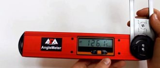
- Goniometers . A measuring tool used to check the accuracy of angles. Mechanical models are equipped with a vernier scale for accurate measurement of deviations.
- Radius and threaded templates . They are a set of plates of a certain shape, designed to determine, respectively, the radius of curvature of a part or the thread pitch by application to the controlled surfaces. Radius templates are available in concave and convex shapes.
The first are used to determine the outer radius, convex - for internal holes. Thread templates allow you to determine the pitch of a metric thread or the number of threads per inch for an inch thread.
- Probes . Sets of measuring plates with a thickness of 0.02 to 1 mm for determining the gaps between mating surfaces. The size of the gap is determined by gradually increasing the thickness of the inserted probes until the maximum is reached.
- Surface roughness samples . Supplied as a kit for determining the roughness parameters of metal parts, the quality of surfaces in hard-to-reach places and monitoring during the production process.
To obtain the most accurate values, you must strictly adhere to the operating instructions for the instrument - do not use excessive force, clean it from dirt, store it in a case, protect it from mechanical shock and fulfill other requirements.
Application of vernier caliper
To carry out high-quality measurements with a vernier caliper. it is necessary to ensure its suitability and performance.
The precise working surfaces of the tool (jaws) must be free of wear and damage and not skewed. The frame should move, but not wobble on the main rod, the working surfaces should not be subject to corrosion, the marks and strokes of the main rod and vernier are clearly legible.
After making sure there is no damage, corrosion, geometric integrity and the ability to move the frame correctly, close the measuring surfaces (jaws) of the tool and look at the clearance.
If there is no wear, the jaws should fit snugly against each other, and the zero strokes of the vernier and the main rod should completely coincide.
When closing the working measuring surfaces, the clearance (according to the standards) should not exceed 3 microns for a measuring instrument with a vernier reading of 0.05 millimeters and 6 microns for a measuring instrument with a vernier reading of 0.1 millimeters.
Indicators
Electronic indicators
They combine analog and digital display. Digital display guarantees error-free reading of the measured values.
Main functions and technical characteristics: digital scale resolution from 0.001 to 0.01 mm; measurement ranges: from 0-12.5 to 0-100 mm; LCD display; display of measurement results in millimeters and inches; zeroing values anywhere in the reading range; direct and comparative measurement modes; RS-232C interface; parameter preset function.
Dial indicators
Mechanical dial indicators with high-precision movement and smooth pointer rotation, have mechanisms with double shock protection for measuring intervals up to 100 mm. The advantage of analogue indication is that the readings vary smoothly according to the size of the sample. This is most suitable for measuring axial and radial runout.
Main functions and technical characteristics: scale divisions 0.001 and 0.01 mm; dial diameters 40, 57, 58, 82 mm.
End gauges
Gauge blocks can be made from a variety of materials.
Steel reference standards have proven their reliability for over a hundred years. This material remains the most used for the manufacture of length standards. Steel master blocks provide high wear resistance together with good adhesion ability to other master blocks. Steel should be protected from corrosion. Standard gauges made from this material are carefully crafted and will remain reliable for many years.
Wolfram carbide. Tungsten carbide reference blocks are 10 times stronger than steel blocks - designed for frequent use.
Ceramic reference standards are exceptionally resistant to wear and scratches. Due to the properties of this material, minor damage will not deteriorate the measuring surfaces. Because the material does not corrode, these reference measures are as resistant to wet hands as others.
Probes
Used to determine the size of gaps. The accuracy of determining the gap size is up to 0.01 mm (depending on the accuracy class). Probe lengths - 50, 100, 200 mm.
Vernier caliper measurement technique
The surface to be measured is pre-cleaned and the ability to carry out high-quality measurements is verified. To take measurements, the instrument is held in the right hand, while the movable frame is moved with the thumb.
After moving the measuring surfaces apart to the distance required to place the part being measured, the instrument is closed with little force.
Correct positioning of the instrument is critical to achieve the minimum possible value (for external measurement) and the maximum possible (for internal measurement). That is, the location of the tool must be strictly perpendicular to the surface being measured.
Measurements with a depth gauge are carried out by directly supporting the end of the tool rod on the plane of the part and pressing the movable frame.
As a result of pressing, the measuring probe will extend to the possible depth.
In the case of marking work, the calipers are equipped with an additional frame (micrometric feed), connected to the main frame by a screw feed, for precise movement.
The main and additional frames have the ability to be rigidly fixed on the main rod to avoid accidental movement.
Criterias of choice
When choosing measuring instruments, you must first take into account the accuracy that will need to be achieved when performing the work. It is indicated in regulatory documents or technical documentation for the part.
In addition, when choosing a measurement tool, you should take into account the maximum deviations, as well as the methods of carrying out work and methods of monitoring them.
The main principle of choosing measuring instruments is their compliance with the stated requirements for obtaining reliable results in compliance with the accuracy specified by the regulations. In addition, it is important to take into account material and time costs: they should be minimal if possible.
Metal measuring ruler
Ruler 1m STAYER “PROFI”, 3427-100_z01
It is difficult to make a mistake if we assume that the first measuring tool that a person gets acquainted with is a measuring ruler, in all its manifestations (tailor's meter, geometric triangle, etc.).
Ease of use and ease of use make it the most common measuring instrument, albeit for not very accurate values.
During manufacturing, the surface of the ruler is equipped with one or two measuring scales, and the production itself and parameters are regulated by GOST.
According to GOST 427-75 from 1975 (which is still relevant today), rulers must be manufactured with the following measurement limits:
- 150 mm;
- 300 mm;
- 500 mm;
- 1000 mm;
- 1500 mm;
- 2000 mm;
- 3000 mm.
Careful GOST also regulates the parameters of applied millimeter, half-centimeter, centimeter strokes, as well as the diameter of the hole for the nail.
Measuring metal rulers are produced from cold-rolled, heat-treated steel tape with a polished surface of strength groups 1P and 2P, followed by galvanic chrome plating.
The zero value of the scale (counting point) coincides with one of the ends, while the second is rounded and equipped with a hole (presumably for a nail, for easy storage).
Each five-millimeter mark (in a centimeter), for ease of reading, is made a little higher than its millimeter counterparts, and the tenth is made even higher and receives a digital designation.
The clearance between the calibration plate and the plane of the ruler, placed on the plate with the scale facing up, should not exceed 0.5 mm for rulers with a scale length of 150, 300, 500; 0.7 - for rulers with a scale length of 1000 mm and 1 millimeter of clearance for rulers more than one meter.
The permissible deviation of the scale dimensions of a meter metal ruler is +/- 0.2 millimeters.
Measuring tool: application
Any measuring device has initially configured factory parameters that can be adjusted to achieve ideal accuracy. In this case, you need to pay attention to the permissible error range, which will still exist. This point is very important when making parts that will later be connected.
If the dimensions do not match, then it will be impossible to assemble the structure. To measure such precise parameters, calibers or a caliper tool are used. At the same time, you need to be able to use the tool correctly and understand what it shows.
Errors in data interpretation lead to actions that are subsequently reflected in the form of premature breakdowns, distortions, and inconsistencies of parts. Also, contamination and wear of measuring devices lead to large errors in the display of real parameters.
It is necessary to carefully monitor the condition of all devices that are used for measurements, repair, clean, and replace worn parts. The price of a mistake is high - life, lost health. When manufacturing, testing, and using high-precision parts, structures, and devices, you must always remember this and avoid making annoying mistakes.
Operation of a metal measuring ruler
The coincidence of the zero mark (reference point) with the end of the ruler allows you to measure holes, grooves, protrusions, steps and axial distances that do not require high accuracy.
The ease of use of a metal measuring ruler allows you to take measurements using the application method. Often the object under study is photographed together with a ruler in order to subsequently navigate the geometric parameters.
To determine the interaxial distance of holes with the same diameters (if the design of the part allows you to attach the measuring tool to the plane), use a ruler to measure the distance of the same surfaces (right edges of holes, left edges of holes), trying to ensure that the measurement occurs through the centers.
terms of Use
The choice of measuring and control instruments is made based on the technical regulations for the selected instruments under conditions of their normal operation and use.
Normal conditions are those conditions under which the values of the factors influencing the result can be omitted due to their smallness. The described conditions are usually specified in the instructions for measuring instruments or calculated during their calibration.
A distinction should be made between the operating conditions and the limiting conditions of the measurements being taken.
Operating conditions are usually considered to be the conditions for performing measurements under which the values of the influencing factors are included in the tolerance of the working areas. In this case, the working area is the range of values of the influencing factor, within which the existing error is normalized or the values of the working tools are changed.
Limit conditions are usually called the maximum and minimum values of actual and influencing quantities that can be maintained by a measuring instrument without major damage and deterioration of its operating properties and characteristics.
When choosing measuring and control instruments for use in working conditions, the relationship between instrument readings and influencing quantities should be taken into account. Based on this, it is necessary to introduce corrections into the final readings of measuring instruments or use corrective devices and instruments.
According to regulatory documents, amendments are determined according to metrological characteristics standardized for workplace conditions.
Test squares
Measurement of angular quantities, a discipline that sometimes has to be addressed in construction or mechanical engineering.
As a measuring tool for these purposes, universal angular meters (with the ability to set angular values) or specialized testing squares are used.
When designing, designers often choose integer angular values 30, 45,
60, 90, 120 degrees.
To mark, check or determine angles, use:
- carpenter's square;
- carpenter's square,
- combined square;
- goniometers;
- protractors;
- level goniometers;
- square-level;
- corner levels, etc.
When checking right angles, squares are used.
Squares whose sides do not exceed 500 millimeters are made of case-hardened steel, followed by heat treatment and hardening of the surface.
Test squares are divided into accuracy classes:
- zero accuracy class;
- first class of accuracy;
- second class of accuracy;
- third class of accuracy.
The most accurate is zero.
Spirit ( Level ) is a device used to determine the horizontalness of a surface. A spirit level is a bar in which is fixed a transparent glass tube filled with liquid, usually alcohol, with a small gas bubble. The tube with liquid has an arcuate longitudinal section. If the tube with liquid is located horizontally, the gas bubble is located strictly in the middle of the tube. Typically, a spirit level contains two tubes with liquid for checking horizontal and vertical surfaces.
Calipers are a tool used to determine the external dimensions of parts. The readings are taken using a measuring ruler with an accuracy of about 0.5 mm. The caliper consists of two curved, hinged legs.
A curvimeter is a device used to measure tortuous curved segments, mainly on topographic maps. When making measurements, the cogwheel of the curvimeter is rolled along a winding line on the map. The distance traveled is measured using the dial. Typically, a mechanical curvimeter is equipped with two dials, one of which is graduated in centimeters and the other in inches. The measurement error of a mechanical curvimeter is 0.5%.
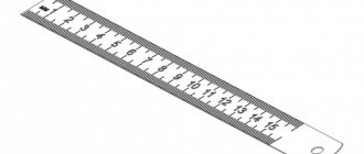
A measuring ruler is a tool with which linear dimensions are measured. Using a measuring ruler, the readings of measuring instruments such as calipers, bore gauges, etc. are taken. The ruler scale has a division value of 1 mm or 0.5 mm. Every 5mm, the stroke on the ruler is slightly larger. Every 1 cm, an even more elongated stroke is provided with a number indicating the number of centimeters before the beginning of the scale.
A checking ruler is a tool used to check the straightness of surfaces.
Malka is a tool with which the dimensions of angles are transferred from a part to a goniometer tool or to a workpiece. Wooden block is used in carpentry work . It is a block with a slot and a feather . The feather and the block are pivotally connected using a screw and a wing nut. In order to install the pen in the desired position, you need to loosen and then tighten the knob. In the non-working position, the feather is retracted into the slot of the block, while the small one does not take up much space. When carrying out metalwork marking work, a metal .
A micrometer is an instrument with which measurements are made with an accuracy of 0.01 mm. The micrometer includes a bracket with a heel , a micrometer screw with a pitch of 0.5 mm and a stopper . The micrometer screw consists of a stem , a drum , and a head . The longitudinal scale applied to the stem is divided by a mark into the main and auxiliary ones so that the distance between the marks of the two scales is 0.5 mm. The circumference of the drum is divided into 50 equal divisions. Rotating the drum by one division moves the micrometer screw by 0.01 mm. Ratchet , which is equipped with the head, allows you to transmit a constant force to the micrometer screw. In the case when the micrometer screw rests on the heel, the end of the drum should align with the zero division of the main longitudinal scale. In this case, the zero division of the circular scale on the drum must coincide with the longitudinal mark of the main scale. In the figure shown, the end of the drum has moved 16 divisions from zero on the main scale and another division on the auxiliary scale. The 37th division of the circular scale of the drum was combined with the longitudinal mark of the main scale. Thus, the size plotted on the micrometer is: 16 + 0.5 + 0.37 = 16.87 mm.
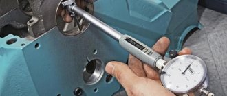
A bore gauge is a tool used to determine the internal dimensions of parts. The readings are taken using a measuring ruler with an accuracy of about 0.5 mm. The bore gauge consists of two legs connected by a hinge. The lower ends of the legs are curved outward.
A plumb line is a device used to check the verticality of structures such as pillars, supports, brickwork, etc. A plumb line consists of a thin thread with a weight attached to its end. The weight is usually given the appearance of a cylinder, sharpened into a cone.
The marking plate is the main marking device. All dimensions are measured from the surface of the slab, which are marked by marks on the parts during spatial markings. Marking plates are made by casting from fine-grained gray cast iron. At the bottom of the slab there are stiffening ribs that prevent it from bending under the weight of the parts being marked and under the weight of the slab itself. The working plane of the slab is processed on precision planing machines and then scraped. To facilitate the installation of various devices on the stove, the working surface of the plates is sometimes divided into squares by grooves 2 - 3 mm deep and 1 - 2 mm wide.
Testing and marking prisms are devices used to check and mark shafts and cylindrical parts. Prisms are manufactured in sets in pairs, which allows them to be used as supports when inspecting and marking long cylindrical parts.
A thread gauge is a measuring tool that is a set of various thread templates. The thread gauge is used to measure the pitch of a metric thread, or for an inch thread the number of turns per inch. A thread template is a toothed plate with a specific tooth pitch. Each metric template indicates the thread pitch in millimeters, and each inch template indicates the number of turns per inch of thread. A set of templates is placed in a frame of two overlays, fastened with screws. The metric thread gauge is marked: “M60°”, and the inch thread gauge is marked “D55°”.
A bench thicknesser is a marking tool used for spatial marking of parts. A stand to the base of the surface planer in the required position using a nut . The tilt of the stand at a slight angle is ensured by a set screw. The scriber is installed on the stand and secured in the desired position with a nut. The thicknesser and the part are placed on the marking plate. Place the stand and scriber in the required position. Move the thicknesser around the part. Using a scriber, marks are made on the part at an equal distance from the surface of the marking plate.
A bench square is a tool used to check and mark right angles. A square is also convenient for drawing straight parallel lines. A square is used to check the perpendicularity of parts during equipment assembly. There are flat squares, squares with a “heel” , full squares.
A center finder is a square that is used to find the center of a cylindrical part. The center finder consists of a ruler mounted on a square in such a way that one of the edges of the ruler is a bisector of the right angle of the square. To determine the center of the circle, place a square on the end of the part so that both of its faces touch the side surfaces of the part. Using a ruler, apply a mark to the part using a ruler. Rotate the square to a certain angle and repeat the operation. The intersection of the two marks is the center of the circle.
Marking compass is a tool with which markings in the form of arcs or circles are applied to the materials being processed. Compasses are also used to transfer dimensions from the ruler to the part. For a tightly compressed compass, the ends of the legs should meet without any gap. The sharply sharpened ends of the legs are hardened. The required distance between the legs of the compass is fixed using an arc and a screw . Before drawing a circle or arc onto the material, it is necessary to mark their center with a center punch.
A scriber is a tool that is used to mark marks in the form of marks on the materials being processed. The scriber is made from tool steel. The edge is hardened. For ease of operation, the middle thickened part of the scriber is rolled. Sometimes, to make marks in hard-to-reach places, one end of the scriber is bent at a right angle.
A caliper is a tool with which measurements are made, the error of which does not exceed 0.1 mm. A caliper allows you to measure external and internal dimensions, as well as depth. A rod with millimeter graduations ends on one side with a depth gauge , and on the other side with fixed jaws . Movable jaws are adjacent to the fixed jaws . The movable jaws are equipped with an auxiliary scale called a vernier . Using a vernier it is possible to make measurements with an accuracy of 0.1 mm. Movable jaws can move freely along the rod. In the desired position, the movable jaws are fixed using a locking screw .
The vernier scale, 19 mm long, is divided into parts, 1.9 mm each. In the case when the zero line of the vernier aligns with one of the scale divisions on the rod, the remaining divisions of the vernier (except for the last tenth) will not coincide with the divisions of the main scale. The first line of the vernier and the second division of the millimeter scale differ by 0.1 mm. The second division of the vernier and the fourth division of the rod are 0.2 mm, the third and sixth are 0.3 mm, the fourth and eighth are 0.4 mm, the fifth is in the middle between the ninth and tenth. When making measurements, whole millimeters are counted on the main scale on the rod opposite the zero division of the vernier. Tenths of a millimeter are counted according to the division of the vernier, which coincides with the division of the main scale on the rod. The illustration shows examples of sizes 0.1mm, 0.3mm and 88.4mm. There are designs of calipers capable of making measurements, the error of which does not exceed 0.05mm and 0.02mm.
Say “thank you” to the author.
Mechanical micrometer
Mechanical micrometer, BISON "EXPERT" MK 125, 34480-125_z01
Mechanical micrometers are a universal tool for precise measurements using the contact method. The measurement accuracy of micrometers is from 0.002 to 0.05 millimeters (depending on the measurement parameters and accuracy class).
Mechanical micrometer design
Structurally, a mechanical micrometer is a horseshoe-shaped bracket.
On one side of the bracket there is a measuring heel, and on the other, the micrometer mechanism itself (stem).
The stem consists of:
- drum with ratchet;
- micrometer screw;
- stopper
The main elements of the measuring device are a micrometric screw and a micrometric nut.
The micrometer screw pair converts the angular movement of the drum into the linear movement of the micrometer screw.
Full revolutions are counted on a scale marked on the stem of the micrometer, and fractions of a revolution are counted on a circular scale marked on the drum.
Due to the difficulty of manufacturing an accurate screw pair over a long length, it is considered optimal to move the screw in the nut only to a length of no more than 25 millimeters.
For this reason, for measurement, several standard sizes of micrometers are made, in increments of 25 millimeters:
- 0-25 mm;
- 25-50 mm;
- 50-75 mm;
- 75-100 mm, etc.
The maximum measuring range of the largest micrometer ends at three meters.
When measuring lengths of more than 25 millimeters, micrometers with replaceable heels are used, and such a micrometer is set to zero using gauge blocks.
Classification
Manual and mechanical testing and measuring instruments are divided into the following classes:
- Scaleless – calibration and measuring rulers;
- Micrometric;
- Vernier tool;
- Gear-lever;
- Spring-loaded.
Each device has its own initial parameters, a certain strict range, and errors. It is impossible to measure anything absolutely accurately. But the lower the error, the more expensive the device.
Measurement errors are also affected by the following reasons:
- Incorrect application;
- Malfunction;
- Pollution.
According to GOST, control and measuring devices are divided into the following main groups:
- Calibers (smooth, threaded, complex, profile);
- Pneumatic devices;
- Electromechanical devices;
- Measures, calibration instrument;
- Optical-mechanical;
- Vernier;
- Mechanical.
The calibers are of a special type, the rest are of a universal type. The latter type of measuring devices allows you to study the parameters of a product of any configuration.
The universal tool is widely used. This type includes:
- Vernier tool: compass, depth gauge, thickness gauge;
- Micrometer;
- Level;
- Squares;
- Templates;
- Probes.
Also, the simplest measuring instruments include tape measures, ordinary school rulers, and squares.
Making a choice
The selection and assignment of measuring instruments is carried out by departments that are involved in the development of:
Technological processes of product standardization, measurement of its components and materials.
The selection of measurement tools and methods based on the available initial data is made by qualified employees. They should be well acquainted with the basics of physical measurements, with the methods of formatting and using measurement results and errors, as well as with the principles of normalizing metrological parameters and calculating instrument errors from them.
To carry out measurements during the manufacturing process, special workers are appointed who are responsible for measuring instruments.
In conclusion, we can say that the correct choice of measuring instruments from the currently available range is the key to efficient production and reducing the number of defective products.
