Vickers and Shore methods for hardness testers
09.11.2017
Vickers hardness: methodology and equipment
Vickers hardness (HV) is determined by indenting a diamond pyramid that has an apex angle of 136º. Vickers hardness is the hardness of a material calculated from the size of the indentation produced by loading a diamond pyramid of an indenter. The indenter used in Vickers tests is a pyramid with a square base, the opposite sides of which meet at the apex at an angle of 136º. It is regulated by GOST 2999-75* (ST SEV 470-77) “Method for measuring Vickers hardness” and ISO 6507. Vickers hardness is calculated by dividing the load P
by the surface area of the resulting pyramidal imprint. The Vickers method allows you to determine the hardness of nitrided and cemented surfaces, as well as thin sheet materials. There is good agreement between the Vickers and Brinell hardness values in the range from 100 to 450 HV. The main parameters when measuring Vickers hardness are load P up to 980.7 N (100 kgf) and holding time 10-15 s.
As a result of the penetration, a diamond-shaped imprint (sometimes an irregular one) remains on the surface of the sample under study. Based on the value of the diagonal of this rhombus (or the arithmetic average of both diagonals), the Vickers hardness number, which has the dimension of mechanical pressure, is determined.
The equipment produced, with the help of which Vickers hardness is determined, refers to static machines. They can be stationary and portable. The range of types of such domestically produced equipment is labeled TP (Pyramidal Hardness).
Standard conditions for testing are:
- The measuring range of loading forces is 49-1176 N, which in TP hardness testers has 7 positions (step-changeable);
- The holding time of the sample under pressure is at least 5 s.
- The principle of measuring fingerprint diagonals
The Vickers number (HV) is calculated using the formula:
HV = 2Psin (0.5α/d2 ) = 1.8544Р/ d2
,
where P
is the applied load (kgf),
d
is the average diagonal of the indentation (mm) and
α
is the face angle of the indenter (136°)
When measuring Vickers hardness, the following conditions must be met:
- smooth increase in load to the required value
- ensuring that the applied force is perpendicular to the surface being tested
- the surface of the test sample must have a roughness of no more than 0.16 µm
- maintaining a constant applied load for a set time
- the distance between the center of the print and the edge of the sample or adjacent print must be at least 2.5 times the length of the diagonal of the print
- the minimum sample thickness for steel products should be 1.2 times greater than the indentation diagonal; for products made of non-ferrous metals – 1.5 times.
Vickers hardness HV measurement is performed in the following sequence.
- The sample or part is placed on the instrument table with the surface to be measured upward. After this, the table is raised up by rotating the flywheel handle until it makes light contact with the indenter.
- The lever is released, thereby setting the loading mechanism in motion. After the measurement duration is set using a time relay, the load is removed and the working head, with the indenter fixed in it, returns to its original position.
- After this, you can turn the instrument table with the sample towards the reading microscope on the hardness tester frame and measure the diagonals of the indentation.
Preliminary settings for the Vickers hardness tester are made using the adjustment knob. In this case, as the thickness of the sample decreases, the load should be taken less. Vickers hardness is sometimes quoted at the working load value. For example, the designation HV50940 means a Vickers hardness of 940 units, which was obtained after loading the sample with a force of 50 kg.
More examples of notation:
- 500 HV - Vickers hardness obtained under load F=30 kgf and holding time 10-15 s;
- 220 HV 10/40 - Vickers hardness obtained at a load of 98.07 (10 kgf) and a holding time of 40 s.
Advantages of the Vickers method:
- Constancy of the ratio of the diagonals of the resulting print when the workload changes.
- The ability to determine the hardness of very thin layers of product material, since in the extreme position the indenter has a very small surface area.
- Increased accuracy of the result due to the high hardness of the diamond pyramid of the indenter and the absence of deformation of the test head itself. Vickers hardness measurement is characterized by increased accuracy, because The indentation diagonal d is measured using a microscope specially installed on a hardness tester with an accuracy of 1-2 µm.
- The wide measurement range covers relatively soft metals (aluminum, copper, etc.) and high-strength steels and hard alloys.
- The Vickers method allows you to determine the hardness of individual layers of metal , for example, a sample cemented during chemical-thermal treatment, or a layer with a changed chemical composition (after surface hardening or alloying). In addition to galvanized surfaces, the method is also applicable to nitrided materials.
The disadvantages of the method include the dependence of the measured hardness on the applied load or the depth of penetration of the indenter (the phenomenon of the size effect, often called indentation size effect in English literature).
This dependence is especially pronounced at low loads. Also, the disadvantages of the method include the need to obtain a surface with low roughness and a relatively long test time. The practical range for Vickers hardness measurement is 145-1000 HV. Due to the high accuracy of the method, automated installations with hydraulic and electromechanical drives, as well as automated reading of the results, which are displayed on the monitor, are widely used to evaluate the HV parameter of large batches of workpieces.
Shore hardness: methodology and equipment
Shore hardness is one of the methods for measuring the hardness of materials. Typically used to measure the hardness of low modulus materials. Usually - polymers: plastics, elastomers, rubbers and their vulcanization products.
To measure with a Shore durometer (hardness tester), several scales are used, used for materials with different properties. The two most common scales are type A and type D. Type A scale is for softer materials, D for harder materials. In addition, the ASTM D2240 standard provides a total of 12 measurement scales used depending on the target application; There are types A, B, C, D, DO, E, M, O, OO, OOO, OOO-S and R. All scales are divided from 0 to 100 arbitrary units, with higher values corresponding to harder materials.
The method is characterized by a relatively large scatter of measurement results, but is convenient due to its simplicity (including the design of the measuring device) and efficiency of measurements, allowing them to be carried out, including on finished products, large-sized parts and curved surfaces of sufficiently large radii. Because of this, it has become widespread in industrial practice.
The measuring principle is as follows:
When testing materials whose hardness does not depend on relative humidity, the durometer and test samples are conditioned for at least 1 hour in one of the standard atmospheres in accordance with GOST 12423 (ISO 291), protecting them from exposure to direct sunlight. When testing materials whose hardness depends on relative humidity, test specimens should be conditioned to the same standards or in accordance with the relevant specifications for the material being tested.
The test is carried out under the same conditions.
The test sample must have a thickness of at least 6 mm. The test specimen may be composed of several thin layers to achieve the required thickness, but the test results obtained with such specimens may not be consistent with the results of tests on solid specimens because the surfaces of such layers are sometimes not completely in contact with each other.
The dimensions of the specimens shall permit testing to be carried out at a distance of at least 12 mm from any edge, unless it is known in advance that identical results will be achieved when tested at a smaller distance from the edge. The surface of the sample at the point of contact with the supporting surface in an area with a radius of at least 6 mm from the tip of the indenter must be very smooth. On curved, uneven or rough surfaces, satisfactory hardness readings cannot be obtained using a durometer.
The test sample is placed on a hard, flat, horizontal surface. The durometer is installed in a vertical position so that the tip of the indenter is at a distance of at least 12 mm from any edge of the sample. As quickly as possible, without pushing, press the support surface of the durometer onto the sample, keeping it parallel to the surface of the test sample. Sufficient pressure is applied to the supporting surface using a special device or weight to ensure reliable contact with the sample.
Shore hardness is designated as a numerical scale value, to which is attached a letter indicating the type of scale with an explicit indication of the name of the hardness measuring method or device.
- For example: “Hardness Shore 80A.”
- For example: “Durometer hardness 80A.”
- Allowed: “Hardness 80 Shore D.”
- In the tables the following designation is allowed: “Hardness, units. Shore(s) A.”
The method allows you to measure the depth of initial indentation, the depth of indentation after specified periods of time, or both.
The method is an empirical test. There is no simple relationship between the hardness determined by this method and any fundamental property of the material being tested.
Shore hardness is indicated rounded to the nearest whole unit. In the Shore scale, the maximum hardness of a carbon tool steel sample stabilized after martensite quenching is taken as 100 units, which corresponds to a striker drop height of 13.6 ± 0.3 mm.
The method is characterized by a relatively large scatter of measurement results, but is convenient due to its simplicity (including the design of the measuring device) and efficiency of measurements, allowing them to be carried out, including on finished products, large-sized parts and curved surfaces of sufficiently large radii. Because of this, it has become widespread in industrial practice.
Relationship between some Shore durometer scales
Approximate ratio of different scales
| A | 5 | 10 | 15 | 20 | 25 | 30 | 35 | 40 | 45 | 50 | 55 | 60 | 65 | 70 | 75 | 80 | 85 | 90 | 95 | 100 |
| B | 6 | 12 | 17 | 22 | 27 | 32 | 37 | 42 | 47 | 51 | 56 | 62 | 66 | 71 | 76 | 81 | 85 | |||
| C | 9 | 12 | 14 | 17 | 20 | 24 | 28 | 32 | 37 | 42 | 47 | 52 | 59 | 70 | 77 | |||||
| D | 6 | 7 | 8 | 10 | 12 | 14 | 16 | 19 | 22 | 25 | 29 | 33 | 39 | 46 | 58 | |||||
| O | 8 | 14 | 21 | 28 | 35 | 42 | 48 | 53 | 57 | 61 | 65 | 69 | 72 | 75 | 79 | 84 | ||||
| O.O. | 45 | 55 | 62 | 70 | 76 | 80 | 83 | 86 | 88 | 90 | 91 | 93 | 94 | 95 | 97 | 98 |
Device structure
The design of Shore durometers includes the following parts:
- A supporting surface (an area of at least 100 mm²) with a hole with a diameter of 2.5 to 3.5 mm, the center of which is at least 6 mm from any edge of the support.
- Indenter in the form of a hardened steel rod with a diameter of 1.10–1.40 mm (see drawing).
- An indicator device showing the degree of extension of the indenter tip beyond the supporting surface. The degree of extension can be measured directly in arbitrary units ranging from 0, for full extension of the indenter tip, equal to 2.50 mm + 0.04 mm, to 100 if there is no extension at all, which occurs, for example, in the case when the supporting surface of the indenter is pressed tightly against the glass plate.
- A calibrated spring for applying a force to the indenter, calculated according to one of the following formulas:
a) F = 550 + 75N A
, where
F
is the applied force, mN;
H A
- hardness determined using a type A durometer;
b) F = 445N D
, where
F
is the applied force, mN;
H D - hardness determined using a type D durometer.
Table No. 1 For converting hardness and tensile strength numbers
(to enlarge, click on the table, the image will open in a separate window)
Download the table in pdf: Table No. 1 For converting hardness and tensile strength numbers.
The conversion of hardness numbers and tensile strength σв will be useful for specialists involved in the heat treatment of steels, non-ferrous metals and alloys. They can also be useful when conducting studies of the heat-affected welding zone - you can see how the hardness changes with distance from the seam, on the basis of which you can draw a conclusion about the mechanical properties of the seam, since the hardness values can be converted to σw. In table No. 1, the value of σв ends at 690 N\mm2 (70 kgf\mm2), which corresponds to 21 HRC - a rare weld has such hardness, except that after hardening in some cases it can be more than 21 HRC, provided that the metal has a sufficient amount carbon, alloying elements and the structure of the metal after heat treatment - martensite. After welding, the seam and heat-affected zone are in a tempered state if the base metal has been previously hardened. In this case, it can be examined using the HRA scale (see Table No. 2) or using the Brinell method.
Rockwell hardness test
The Rockwell hardness measurement method is regulated by GOST 9013. When determining hardness by this method, the test sample under the influence of two sequentially applied loads - preliminary P0 (usually P0 = 10 kgf) and total P - is pressed by an indenter (diamond cone or steel ball). In this case, the total load is equal to the sum of the preliminary P0 and main P1 loads:
P = P0+P1
After holding under the applied total load P for 3...5 s, the main load P1 is removed and the depth of penetration of the indenter into the material A is measured under the influence of the total load P, then the remaining preliminary load P0 is removed.
Rockwell hardness is measured in arbitrary units. The unit of hardness is taken to be the value corresponding to the axial movement of the indenter by 0.002 mm. The hardness number is determined using an indicator scale (usually a dial type). The indicator shows the result of subtracting the difference in depths (h – h0) to which the indenter is pressed under the action of two sequentially applied loads from a certain constant. The value h0 is the depth of penetration of the indenter into the test sample under the influence of preload P0.
Depending on the shape of the indenter and the applied load, three measuring scales are introduced: A, B, C. The most commonly used scales are A and C.
The Rockwell hardness number is indicated by numbers characterizing the hardness value followed by the symbol HRA, HRB or HRC (depending on the measurement scale used), for example: 28 HRC
Scales used to measure Rockwell hardness
Table of correction factors for measurements on curved surfaces
B.1 Spherical surfaces
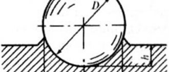
Tables B.1 and B.2 give correction factors when hardness measurements are made on spherical surfaces.
Correction factors are given for the ratio of the average length of the print diagonals to the diameter D
spherical sample on which measurements are performed.
Example
:
The diameter
of the spherical sample is D
=
10 mm
.
Load
F
=
98.07
N.
_
_ _
The average
length print diagonals is d
=
150 mm
.
Vickers hardness
= _
The correction
factor is obtained from Table B.1 by interpolation
= ,
983
.
The hardness
of
the spherical sample
is
824 ×
0.983 =
810 H V 10
.
Table B.1 – Convex spherical surfaces
| d / | Correction factor | d / | Correction factor |
| 0,004 | 0,995 | 0,086 | 0,920 |
| 0,009 | 0,990 | 0,093 | 0,915 |
| 0,013 | 0,985 | 0,100 | 0,910 |
| 0,018 | 0,980 | 0,107 | 0,905 |
| 0,023 | 0,975 | 0,114 | 0,900 |
| 0,028 | 0,970 | 0,122 | 0,895 |
| 0,033 | 0,965 | 0,130 | 0,890 |
| 0,038 | 0,960 | 0,139 | 0,885 |
| 0,043 | 0,955 | 0,147 | 0,880 |
| 0,049 | 0,950 | 0,156 | 0,875 |
| 0,055 | 0,945 | 0,165 | 0,870 |
| 0,061 | 0,940 | 0,175 | 0,865 |
| 0,067 | 0,935 | 0,185 | 0,860 |
| 0,073 | 0,930 | 0,195 | 0,855 |
| 0,079 | 0,925 | 0,206 | 0,850 |
Table B.2 – Concave spherical surfaces
| d / | Correction factor | d / | Correction factor |
| 0,004 | 1,005 | 0,038 | 1,050 |
| 0,008 | 1,010 | 0,041 | 1,055 |
| 0,012 | 1,015 | 0,045 | 1,060 |
| 0,016 | 1,020 | 0,048 | 1,065 |
| 0,020 | 1,025 | 0,051 | 1,070 |
| 0,024 | 1,030 | 0,054 | 1,075 |
| 0,028 | 1,035 | 0,057 | 1,080 |
| 0,031 | 1,040 | 0,060 | 1,085 |
| 0,035 | 1,045 | 0,063 | 1,090 |
| 0,066 | 1,095 | 0,082 | 1,125 |
| 0,069 | 1,100 | 0,084 | 1,130 |
| 0,071 | 1,105 | 0,087 | 1,135 |
| 0,074 | 1,110 | 0,089 | 1,140 |
| 0,077 | 1,115 | 0,091 | 1,145 |
| 0,079 | 1,120 | 0,094 | 1,150 |
B.2 Cylindrical surfaces
Tables B.3 - B.6 give correction factors when hardness measurements are performed on cylindrical surfaces.
Correction factors are given for the ratio of the average length of the print diagonals to the diameter D
cylindrical sample on which measurements are performed.
Example
:
Cylindrical
sample
,
one of imprint diagonals is parallel to cylinder axis D
=
5 mm
.
The average
length print diagonals is d
=
415 mm
.
Load
F
=
294.2
N.
_
_ _
Vickers hardness
= _
The
correction
factor is
obtained from table B.6
=
1.075 .
Hardness of
a
cylindrical sample
=
323 ×
1.075 =
347 H V 30
.
Table B.3 – Convex cylindrical surfaces. Diagonals are rotated 45° relative to the cylinder axis
| d / | Correction factor | d / | Correction factor |
| 0,009 | 0,995 | 0,119 | 0,935 |
| 0,017 | 0,990 | 0,129 | 0,930 |
| 0,026 | 0,985 | 0,139 | 0,925 |
| 0,035 | 0,980 | 0,149 | 0,920 |
| 0,044 | 0,975 | 0,159 | 0,915 |
| 0,053 | 0,970 | 0,169 | 0,910 |
| 0,062 | 0,965 | 0,179 | 0,905 |
| 0,071 | 0,960 | 0,189 | 0,900 |
| 0,081 | 0,955 | 0,200 | 0,895 |
| 0,090 | 0,950 | ||
| 0,100 | 0,945 | ||
| 0,109 | 0,940 |
Table B.4 – Concave cylindrical surfaces. Diagonals are rotated 45° relative to the cylinder axis
| d / | Correction factor | d / | Correction factor |
| 0,009 | 1,005 | 0,082 | 1,050 |
| 0,017 | 1,010 | 0,089 | 1,055 |
| 0,025 | 1,015 | 0,097 | 1,060 |
| 0,034 | 1,020 | 0,104 | 1,065 |
| 0,042 | 1,025 | 0,112 | 1,070 |
| 0,050 | 1,030 | 0,119 | 1,075 |
| 0,058 | 1,035 | 0,127 | 1,080 |
| 0,066 | 1,040 | 0,134 | 1,085 |
| 0,074 | 1,045 | 0,141 | 1,090 |
| 0,148 | 1,095 | 0,189 | 1,125 |
| 0,155 | 1,100 | 0,196 | 1,130 |
| 0,162 | 1,105 | 0,203 | 1,135 |
| 0,169 | 1,110 | 0,209 | 1,140 |
| 0,176 | 1,115 | 0,216 | 1,145 |
| 0,183 | 1,120 | 0,222 | 1,150 |
Table B.5 – Convex cylindrical surfaces. One of the diagonals is parallel to the cylinder axis
| d / | Correction factor | d / | Correction factor |
| 0,009 | 0,995 | 0,085 | 0,965 |
| 0,019 | 0,990 | 0,104 | 0,960 |
| 0,029 | 0,985 | 0,126 | 0,955 |
| 0,041 | 0,980 | 0,153 | 0,950 |
| 0,054 | 0,975 | 0,189 | 0,945 |
| 0,068 | 0,970 | 0,243 | 0,940 |
Table B.6 – Concave cylindrical surfaces. One of the diagonals is parallel to the cylinder axis
| d / | Correction factor | d / | Correction factor |
| 0,008 | 1,005 | 0,087 | 1,080 |
| 0,016 | 1,010 | 0,090 | 1,085 |
| 0,023 | 1,015 | 0,093 | 1,090 |
| 0,030 | 1,020 | 0,097 | 1,095 |
| 0,036 | 1,025 | 0,100 | 1,100 |
| 0,042 | 1,030 | 0,103 | 1,105 |
| 0,048 | 1,035 | 0,105 | 1,110 |
| 0,053 | 1,040 | 0,108 | 1,115 |
| 0,058 | 1,045 | 0,111 | 1,120 |
| 0,063 | 1,050 | 0,113 | 1,125 |
| 0,067 | 1,055 | 0,116 | 1,130 |
| 0,071 | 1,060 | 0,118 | 1,135 |
| 0,076 | 1,065 | 0,120 | 1,140 |
| 0,079 | 1,070 | 0,123 | 1,145 |
| 0,083 | 1,075 | 0,125 | 1,150 |
Application area
Hardness measurement using the Vickers method is a universal method, but it gives the most accurate values when studying substances with high hardness. Low forces and, accordingly, small linear dimensions of the print make it possible to practically not disturb the surface of the material being measured.
The Vickers method was further developed in microhardness measurements. The pressure ranges from 2 to 500 g, and the immersion depth of the indenter does not exceed 0.2 μm. Such small values require the use of microscopes with high magnification power.
Vickers hardness tester
The reason for using this technique is to measure the strength of coatings of almost any thickness and hardness. Thus, there are no fundamental restrictions on the characterization of anodized, cemented and nitrided parts and tools. This is important when determining the quality of galvanic and chemical coatings.
Measurements of very thin surface layers are possible. For example, if we use the Vickers method for determining microhardness with an immersion depth of 0.2 µm, then the permissible material thickness is 0.3 µm. The depth of the hardened steel layer using various techniques is tenths of a millimeter, the thickness of the rhodium layer is tens of micrometers.
In domestic laboratories, the most common type of hardness tester is TP-7R-1. It has five fixed test load values with HV measurement limits from 8 to 2000.