Preparation for welding
Cutting and preparing the edges of parts made of aluminum and its alloys should be carried out using mechanical methods
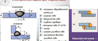
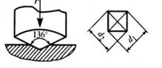
Butt joints of metal of different thicknesses
Structural elements for edge preparation (dimensions in mm)
Structural elements of edge preparation when welding with through penetration and formation of a seam in weight
When welding in one pass, a cut in the root of the seam may occur.
When chamfering from the reverse side of the edges being joined, a cut does not occur. You can use a file to remove chamfers
The surfaces to be welded are thoroughly cleaned of grease, and degreased with acetone, white spirit or other solvent at a width of 100-150 mm from the edges.
The aluminum oxide film is removed mechanically or chemically.
During mechanical processing (immediately before welding), the edges are cleaned to a width of 25-30 mm with abrasive paper, a scraper or a brush made of stainless wire with a diameter of no more than 0.15 mm.
Chemical etching is carried out for 0.5-1 minutes in a solution consisting of 50 g of caustic soda and 45 g of sodium fluoride per 1 liter of water. After etching, the surface is washed with running water and then brightened in a 30-35% solution of nitric acid (for aluminum and AMts type alloys) or in a 25% solution of orthophosphoric acid (for AMg and B95 type alloys). After repeated washing, the surface is dried until the moisture has completely evaporated.
Aluminum welding wire is also treated before welding. First, it is degreased and then etched in a 15% sodium hydroxide solution for 5-10 minutes at 60-70°C. followed by rinsing in cold water and drying at 300°C for 10-30 minutes.
Materials prepared for welding retain their properties for 3-4 days. Later, an oxide film forms on the surface again.
Parts made of aluminum and its alloys are assembled in fixtures or tacks, performed by argon arc welding with a W-electrode. The distance between the tacks should be no more than 150-180 mm.
The surfaces of the tacks are cleaned with metal brushes immediately before welding. Defective tacks found are removed and the joints are re-tacked. When welding, the tacks are completely melted.
Equipment
The equipment may include various components, it depends on the price of the set and the scope of implementation. The usual set includes: a welding machine, a deburring machine, and also a bot or manipulator, with its help you can move large workpieces.
To configure the equipment, it is necessary to set the following parameters: blank size, friction welding speed and spindle drive power.
Experienced welders will have no problem setting up most of these options, but calculating the drive force can be difficult. Therefore, we recommend using the following formula:
Calculation formula
Preparation
When designing workpieces for subsequent welding, it is important to consider a number of factors:
- welding equipment capabilities;
- degree of weldability of materials;
- securing workpieces in a welding machine;
- the cost of preparatory measures for welding workpieces and subsequent processing of welds;
- compliance with the required degree of alignment and angular placement of workpieces;
- formation of a uniform temperature regime and identical deformation conditions;
- correct choice of allowances for the length and diameter of the workpieces.
Ensuring the required alignment depends on the degree of reliability of fastening the parts in the clamping devices of the unit. In this context, the level of rigidity of the welded elements along the length of their exit from the clamps becomes a relevant parameter. If the length of the outlet is less than the required size, this leads to temperature release of the clamping devices.
With friction welding, the condition of the surfaces being joined has the least effect on the quality of the welded joints than with other pressure welding methods. Joining surfaces can be obtained by cutting with a guillotine or a circular saw. Irregularities can be eliminated by lapping or increasing the heating time.
Friction welding technology
Considering technology from the point of view of physical and chemical processes, several sequential processes can be distinguished:
- abrasion of the oxide layer occurs during the contact of parts during movement;
- the weld area is heated to the plasticity temperature of the metal, it is capable of deforming under pressure;
- a single diffuse layer appears during the penetration of molecules of one part into another, due to this, seams are formed on dissimilar and homogeneous metals;
- the formation of a seam bead is caused by the squeezing of ductile metal beyond the joint area;
- fixing the parts to be welded until the diffuse layer hardens;
- the formation of a monolithic structure at the seam, the process of crystallization and the formation of a metal lattice takes place.
During friction, individual protrusions come into contact, and the metal in the friction zone is heated evenly to a small depth. After upsetting, the part cools slowly, forming a joint over the entire joint area.
Advantages and disadvantages
Compared to other types of metal joining, the use of frictional force has good prospects. The method has many advantages:
- the technology is characterized by high productivity, a seam is formed in a few seconds due to the high-speed movement of parts and short-term compression of the workpieces;
- it is possible to obtain strong connections, the percentage of defects is low;
- Consistently good quality of seams: there is no scale, burns, lack of fusion, or porosity;
- no preliminary cleaning of the oxide layer is required;
- the list of welded alloys is wide;
- the technology is safe and does not require conventional welding equipment;
- The process is automated, only large parts have to be installed manually.
Main disadvantages:
- low versatility, the geometry of welded rolled products is limited: rods, pipes, sheet metal, strip, strip;
- dimensional equipment, it is installed permanently, there are no mobile analogues;
- The microstructure of the alloy is disrupted in the area of plastic deformation, the curvature of structural fibers during welding leads to fatigue deformation, and over time the metal loses its former strength.
Flaws
The procedure also has several disadvantages that need to be taken into account. An example is the possibility of breaking the continuity of a seam. In addition, some alloys are less susceptible to friction.
The improvement of the method under consideration has determined that defects form on the surface of the seam in the most extreme cases. Most often this happens when technology is violated and low-quality tools are used.
The technological capabilities of the procedure in question are quite extensive. Let's take the following points as an example:
- Process automation.
- Obtaining quality products at insignificant financial costs.
- Obtaining a seam without a strong influx of metal.
Welding copper and steel
As previously noted, friction stir welding is actively developing today. This is why equipment with higher performance may appear in the future.
Application area
The technology is most widely used in mechanical engineering, primarily in tool production. It is also used in the assembly of internal parts of nuclear reactors. Friction joining of aluminum and magnesium alloy workpieces is popular in electrical engineering, electronics, and aerospace. The technology is also used in transport engineering. The radial method is used in the production of equipment for the mining and processing industries.
The technology demonstrates efficiency and a tendency to replace traditional welding methods in areas such as:
- for replacing soldered and riveted joints;
- to replace contact electric welding;
- for restoration of products and complex tools;
- for welding workpieces to prepared surfaces.
Friction welding in decoration
Linear Welding Equipment
Stir Welding Equipment
Separately, it should be noted that the use of technology provides special advantages where high demands are placed on the environmental friendliness of the production process. High energy efficiency, the absence of splashes of molten metal, harmful fumes and combustion products, ultraviolet radiation and minimal fire hazard make the method particularly advantageous.
Welding mode selection
Each of the described types of welding has several modes, differing in the speed of rotation of the moving parts, the compression force of the workpieces and the thickness of the welding ring (for radial welding). The physical parameters of the modes are determined by the technology of a particular production and all friction welding modes can be divided into three:
- low speed;
- standard;
- accelerated.
Friction welding at low speeds of rotation or friction of parts is used when the viscosity of the materials being welded is high (for example, copper workpieces), as well as when there is a risk of damage to the structure of the fibers of the part. High friction speeds are used when welding low-melting metals and alloys using the stirring method, and high pressure along the axis of rotation is used when welding parts without cavities (solid) using a continuous drive.
Friction Welding Machine
A specialized device is used to create reliable welded joints by plastic deformation of materials that are in a solid state. The high-performance machine has a lot of positive characteristics:
- High class performance.
- The quality of the final welding results is excellent.
- When using machine welding, it is possible to control the quality of the entire batch of products.
- Welding of materials of dissimilar nature is ensured.
- Safety during operation: no UV radiation, hazardous gas emissions and heated metal splashes are eliminated.
Given the relative requirements for workpieces, any machine of this type can be assembled, taking into account the characteristics of a particular customer. This approach solves the problem of creating a new production based on this unique technology.
Friction welding of pipes
Welding using friction technology makes it possible not to use filler materials or the properties of shielding gases when creating a strong seam. The connection of metal pipes occurs without the formation of voids at a thickness of 3 cm. Good quality joints are obtained even when welding aluminum alloys, which, when using alternative technologies, do not show a guaranteed quality result. This welding technology proves its effectiveness when working with alloys of other metals: copper, magnesium, even titanium.
The radial type of friction welding is widely used to create sealed seams on pipelines and individual cylindrical structures. The connection of pipes in non-rotating sections assumes that the two ends of the pipeline are stationary. An additional heated insert is inserted directly into the gap, which will be automatically removed before the forging operation. Connecting pipes using this welding method allows you to create a solid surface with the same weld thickness and strength. This method is used to carry out work on significant sections of pipelines that require strength and safety standards.
svarka-24.info
A new method for producing welded joints, called friction stir welding (FSW), was developed by the British Welding Institute (TWI) in 1991 [1]. Intensive study of this process, aimed at improving technology and equipment, made it possible to introduce this method abroad into the production of high-tech products in such industries as car, ship, aircraft and many others. Friction stir welding refers to processes of joining materials in the solid phase and therefore does not have the disadvantages associated with melting and evaporation of the metal. Process researchers estimate that if 10% of total welded joints in the United States were replaced by FSW, 500 million pounds/year fewer greenhouse gas emissions would be achieved. The estimated economic benefit to US industry from the introduction of STP in industrial production is $4.9 billion/year [2].
The essence of the process is as follows (Fig. 1). For welding, a rod-shaped tool is used, consisting of two main parts, namely: a shoulder or shoulder (thickened part) and a tip (protruding part). The dimensions of these structural elements are selected depending on the thickness and material of the parts being welded.
The length of the tip is set approximately equal to the thickness of the part to be welded. The diameter of the shoulder can vary from 1.2 to 25 mm. A tool rotating at high speed at the joint is brought into contact with the surface of the workpieces so that the tip penetrates into the workpieces to a depth approximately equal to their thickness, and the shoulder touches their surface. The tool then moves along the joint line at welding speed. As a result of the work of friction forces, the metal is heated to a plastic state, mixed with a rotating tool and displaced into the vacated space behind the tool moving along the joint line. The volume in which the seam is formed is limited from above by the shoulder of the tool. At the end of welding, the rotating tool is removed from the joint outside the workpiece. Due to the asymmetry of the structure of the seams in the cross section of welded joints obtained by friction stir welding, it is customary to distinguish between the advancing side, where the direction of rotation of the tool coincides with the direction of welding, and the opposite side, the retreating side.
Rice. 1. Scheme of the friction stir welding process.
FSW is used mainly for joining materials with a relatively low melting point, primarily aluminum [3] and magnesium alloys [4]. Successful welding of copper [5], nickel and titanium alloys [2], as well as steels [6] has been performed using this method. Using FSW, aluminum alloys with a thickness of up to 75 mm are welded in one pass [7]. Friction stir welding makes it possible to obtain lap joints of aluminum sheets with a thickness of 0.2 mm [8]. The welding speed of 5mm thick 6082 alloy can reach 6m/min [9]. The main parameters of the FSW process are: welding speed, tool rotation frequency, pressing and moving forces of the tool, tool inclination angle, and its dimensions. The pressing and moving forces depend on the type of material being welded, its thickness and welding speed. Welding samples from alloy 7010 - T7651 with a thickness of 6.35 mm when changing the welding speed in the range from 59 to 159 mm/min and the tool rotation speed from 180 to 660 rpm showed that with increasing rotation speed, the heat input into the metal and into the welded material increases connection, a microstructure with more uniform grains is formed [10]. At the same time, the strength and plastic properties also increase to a certain limit. As the welding speed increases, it is necessary to increase the tool rotation speed to achieve optimal conditions. However, for the complete absence of defects, as well as to ensure all the necessary properties, reliability and manufacturability, it is necessary to strictly select modes that are optimally suited for a particular product.
Most researchers point to the following advantages of friction stir welding compared to other methods for producing permanent joints [11, 12]:
– in the welding zone, the properties of the base metal are better preserved compared to fusion welding methods;
– absence of harmful fumes and ultraviolet radiation during the welding process;
– the possibility of obtaining defect-free welds on alloys that, during fusion welding, are prone to the formation of hot cracks and porosity in the seams;
– the use of filler material and shielding gas, removal of surface oxides on the edges before welding, as well as slag and spatter after welding are not required;
– there is no loss of metal alloying elements during welding.
The emission levels of Cr, Cu, Mn, Cr+6 during FSW of steels according to Rockwell Scientific (USA) are significantly lower (<0.03, <0.03, <0.02 and <0.01 mg/mm3, respectively) than during argon arc welding (0.25, 0.11, 1.88 and 0.02 mg/mm3, respectively) [2]. A comparison of production costs when using friction stir welding and consumable electrode welding (GEW) showed that the initial investment in FSW is higher, but with increasing production volumes, friction stir welding becomes more economical than arc welding [11].
Rice. 2. Temperature distribution in the longitudinal section of the sample.
Judging by the experimental results of TWI, the maximum temperature during friction stir welding is about 70% of the melting temperature and for aluminum does not exceed 550°C. The heat input during FSW is approximately 2 times less than during argon-arc welding and for the 6N01 – T5 alloy with a thickness of 4 mm is equal to 190 and 390 J/mm, respectively (welding speed 500 mm/min) [13]. Using mathematical modeling of thermal processes during FSW, the temperature distribution in the welded plate was constructed in [14] (Fig. 2). The lower temperature of the joint zone during friction stir welding compared to consumable electrode welding explains the lower level of angular deformation in the welded joint. With FSW, the angular deformation is equal to 1/5÷1/7 of the values with SPE [12] (Fig. 3).
Rice. 3. Comparison of angular deformation between friction stir welding and consumable electrode welding (6000 series aluminum alloy, 2 mm thickness).
It is assumed that due to the low level of process temperatures, residual stresses are low. But rigid fastening imposes great restrictions on the deformation of the plates. This prevents the metal from contracting when cooling the dynamic recrystallization zone and heat-affected zone (HAZ) in the longitudinal and transverse directions, leading to transverse and longitudinal residual stresses. During FSW of alloys 2024 – T3 and 6013 – T6, it was found that the longitudinal residual stresses were higher than the transverse ones (welding speed was 300 ÷ 1000 mm/min, tool rotation speed – 1000 ÷ 2500 rpm). High tensile stresses predominate in the HAZ. The magnitude of residual stresses decreases as the welding speed and tool rotation speed decrease. The maximum values of longitudinal tensile stresses reach values of 30 ÷ 60% of the yield strength of the welded joint and 20 ÷ 50% of the yield strength of the base metal [15].
Rice. 4. Diagram of the zones of the butt joint made by FSW: A – base metal, B – heat-affected zone (HAZ), C – thermomechanical-affected zone, D – dynamic recrystallization zone (running side on the left).
The macrostructure of welded joints in friction stir welding is characterized by features that are not characteristic of welds produced by fusion welding methods. Typical for FSW is the formation of a nucleus in the center of the junction, which contains oval concentric rings that differ in structure [16]. Adjacent to the core is a complex profile that forms the upper part of the seam. The formation of oval rings is associated with the peculiarities of mixing the metal with the tip of the tool. In a welded joint during FSW, four zones are distinguished, which are schematically presented in Figure 4. Directly adjacent to zone A (base metal) is zone B, where the metal of the workpiece remains undeformed and changes its structure only under the influence of heat (heat-affected zone). Zone C, where the metal is subjected to significant plastic deformation and heating, is called the thermomechanical influence zone (TMIA). Zone D is the core of the compound where dynamic recrystallization occurs. The hardness of the metal decreases in the direction from the base metal to the center of the weld, and the minimum value is achieved in the HAZ (Fig. 5). A decrease in hardness in the HAZ occurs due to overaging, a decrease in dislocation density, or due to both of these mechanisms.
Rice. 5. Hardness distribution in the welded joint zone of alloy 7075 – T7351 [17].
Many researchers report a high level of mechanical properties of welded joints. During FSW, the welded joint of the 6082-T6 alloy has a tensile strength σв=245 MPa, while the base metal has σв=317 MPa. For 6082 –T4, aged after welding, σв=308 ÷ 310 MPa. Fatigue tests indicate a higher level of mechanical properties of joints during FSW compared to similar ones during argon arc welding [18].
The authors of [19] conducted studies of the mechanical properties of joints obtained by friction stir welding of alloy 5083 at cryogenic temperatures, which was intended to prepare the production of containers for liquefied hydrogen. Specimens with a thickness of 30 mm were welded at a speed of 40 mm/min. Studies at 77K in liquid nitrogen, 20K in liquid hydrogen and 4K in liquid helium have shown that the level of properties of joints with FSW is higher than with argon arc welding.
Rice. 6. Mechanical properties of a welded joint made by various welding methods.
The authors of [20] dealt with the problems of FSW of cast aluminum alloys. In industrial production, cast alloys often have to be welded to those produced by extrusion. Alloys ADC1 and A6061 – T6 with a thickness of 4 mm were used. The results obtained with FSW were compared with those obtained with argon arc and laser welding. As can be seen from Figure 6, FSW provides better joint properties. The tensile strength is 80% of the strength of A6061 - T6. In bending testing, fracture in friction stir welding occurs along the base metal. Positive results of friction stir welding of dissimilar alloys, as well as aluminum alloys with steels, are reported in publication [21]. In FSW of SS400 steel and A5083 alloy with a thickness of 2 mm, the tensile strength was 240 MPa, which is 86% of the strength of the aluminum alloy.
Rice. 7. Friction stir spot welding machine (left), cross section (top right) and appearance of samples (bottom right).
As a disadvantage of the FSW method, the authors [2, 12] note the formation at the end of the weld of a hole equal to the diameter of the tip, which requires moving the seam beyond the working section of the workpiece or filling the hole after welding using other methods, such as friction welding of special plugs.
The ongoing improvement of technology and equipment makes it possible to overcome existing shortcomings, as well as expand the scope of application of the method. Although friction stir welding is used mainly for butt and lap welds, it is also possible to produce fillet, T, and spot welds. Friction stir spot welding can be implemented in two ways. The first method is immersion spot welding (PFSW), which was patented by Mazda (Japan) in 2003. In this case, a rotating tool is plunged into the part, bringing it to a plastic state and mixing the metal under the shoulder. After this, the tool rises, leaving a characteristic depression in the part. The second method is friction spot welding with seam filling (RFSW), which was patented by GKSS-GmbH in 2002 [2]. For this method, a tool is used whose tip and shoulder have separate drive systems. The rotating tool is lowered into the part, while the tip squeezes out and mixes the metal underneath it, and then it is removed, and the metal under the shoulder fills the recess, and thus a seam without a hole is obtained (Fig. 7).
Rice. 8. Appearance of a tool made of polycrystalline cubic boron nitride [2].
Welding tools are usually made of tool steels H13 (AISI), SKD61, SKD 11, SKH 57 (JIS), stainless martensitic steel SUS440C (JIS). In this case, it is possible to use composite instruments in which the tip is made of cobalt alloy MP159, and the shoulder is made of N13 [22]. For FSW welding of steels up to 0.5″ thick, MegaStir has developed a tool made from polycrystalline cubic boron nitride. Its resistance to fracture is higher and allows you to give the tip the shape necessary for favorable flow of metal in the welding zone (Fig. 8). The tool is positioned at a slight angle of 2 ÷ 3° in relation to the surface of the part [16, 23]. With this arrangement of the tool at a slight angle to the surface of the part, the highest quality indicators are achieved.
Rice. 9. Design of the Bobbin Tool.
The tool, which also serves as a backing for the workpieces to be joined, is shown in Figure 9 [24]. NASA is developing a self-adjusting tool, the length of the tip of which is determined by the forces acting on it. When the load on the tip deviates from the specified value, its length is automatically adjusted. This allows you to weld workpieces of variable cross-section and avoid the formation of holes when making circumferential welds.
Rice. 10. Design options for the WhorlTM working tool.
For welding aluminum alloys of significant thickness, the WhorlTM (Fig. 10) and TrifluteTM [25] families of tools have been developed, which allow welding of aluminum alloys with a thickness of 50 mm in one pass. New options for FSW are Re-StirTM, Skew-StirTM, Com-StirTM technologies [26]. Re-StirTM technology with variable rotation of the tool clockwise and counterclockwise eliminates the seam asymmetry inherent in traditional FSW. Using the Skew–StirTM technology, the tool is slightly inclined in relation to the machine spindle so that the point of intersection of the spindle and tool axes, called the focal point, can be located above, below or in the workpiece being welded, depending on the properties of the material and the mode parameters. This allows you to obtain a wider seam when rotating the tool during the welding process. A – SkewTM and Flare – TrifluteTM tools provide stronger lap joints. Com-StirTM technology consists of combining rotational and orbital movements of the tool during the welding process. As a result, wider seams are obtained and are mainly used to join dissimilar materials. A system with two parallel Twin – StirTM tools has been developed [27].
Rice. 11. Connections made on a Mazda RX – 8 using friction stir spot welding [2].
The development of new friction stir welding technologies continues. At the University of Missouri - Columbia (USA), they are developing FSW with accompanying additional heating when passing current through the tip of the tool. The Center for Processing and Joining of Advanced Materials (USA) is developing FSW with induction preheating of the material, which will increase the welding speed, reduce the forces acting on the tool, and reduce its wear [2]. In [28], the possibility of using a laser for preheating metal during FSW of magnesium alloys is studied.
Rice. 12. Equipment for friction stir welding in a vertical position.
Due to the small number of factors influencing the FSW process and the fairly simple design of the equipment, the method is ideal for automation and robotization [29]. The Tricept805 allows welding of aluminum up to 10 mm thick.
Friction stir welding is already used by many manufacturers of various high-tech products. The companies GDLS (GeneralDynamicsLandSystems) and EWI (EdisonWeldingInstitute) carried out joint work, the purpose of which was to provide the required ballistic characteristics of the connections of armor plates made of aluminum alloy 2195 - T87 for naval armored transporters. Welding using the FSW method instead of argon-arc plates with a thickness of 31.8 mm made it possible to obtain acceptable strength properties of the joints and more ductile (2-3 times) seams. As a result, the welded joints (including fillet joints) successfully passed ballistic tests [22].
Rice. 13. Friction stir welding facility for a Delta rocket fuel tank at Boeing.
To prevent deterioration of the properties of the superconducting Nb – Ti wire, it must be connected to a rigid element made of pure Al at a temperature below 400°C. Previously, low-temperature soldering was used for this, but the soldered seams had low strength. FSW provided the required properties of the welded joint in liquid helium [12].
For three years since 2003, FordMotorCo. (USA) manufactured several thousand Ford GT vehicles using FSW to weld the central compartment, which houses and isolates the fuel tank from the internal compartment and provides spatial rigidity to the frame [2]. FSW improves dimensional accuracy and increases strength by 30% compared to similar units using gas-shielded arc welding. Another work [30] describes the process of manufacturing a MazdaRX-8 car body using friction spot welding (Fig. 11). Since 2003, over 100 thousand cars have been produced whose doors are made by friction spot welding [7]. Based on the successful application of this welding method, the company plans to perform similar connections on the new generation of MX-5 vehicles.
Rice. 14. Eclipse 500 aircraft with friction stir welding components.
They are actively studying the FSW process in the aerospace field (Fig. 12) [24]. In 2001, the process was introduced into the production of the external tank of the launch vehicle for re-entry spacecraft. The technology involves welding 8 longitudinal seams on a 2195 alloy tank for liquid hydrogen and 4 longitudinal seams on a tank for liquid oxygen. That's about ½ mile of seams on each tank. Equipment is being developed for repair friction stir welding in space vacuum conditions. The concept is based on the fact that the high tool rotation speed (30,000 rpm) during FSW will reduce the force required to perform welding.
began using friction stir welding in the production of the Delta II and III rockets (Fig. 13) [31]. Welding is performed on an 8.4 m long fuel tank, a 12 m long liquid oxygen tank and other structures. Friction stir welding provides improved quality (one defect per 76.2 m weld) compared to argon arc welding (one defect per 8.4 m weld). FSW reduces the manufacturing time of a welded structure. Production of Delta II rockets increased from 8 to 17 units per year.
Work on FSW of finned panels for aircraft wings made of alloys 2024, 7475, 7050 with a thickness of 4 mm is reported in article [32]. High quality connections are ensured when using STP on the Airbus A350 aircraft and two new versions of the A340 (A340 - 500 and A340 - 600) [2]. EclipseAviation is completing certification of the Eclipse 500 business jet with FSW components (Fig. 14).
Rice. 15. External view of the experimental setup for FSW of thin-sheet (1.8 ÷ 2.5 mm) aluminum alloys.
The above analysis of published information indicates that friction stir welding is successfully developing and is being used in various branches of industrial production. Most publications concern welding of aluminum alloys of medium and relatively large thickness. It should be borne in mind that difficulties usually arise when connecting workpieces with a thickness of 0.5 - 3 mm, as well as more than 40 mm. In connection with this, as well as with the complications that arise when ensuring the accuracy of the assembly of thin-walled workpieces for welding at the Electric Welding Institute named after. E. O. Paton conducted research on the FSW process on a special experimental setup (Fig. 15). The work was performed on aluminum alloys AMg6, 1201, 1460 with a thickness of 1.8 ... 2.5 mm. In Fig. Figure 16 shows the appearance of a welded joint of the AMg6 alloy produced by the FSW method. At the same time, the effectiveness of welding tools with different working part profiles was tested.
Rice. 16. Appearance of a weld obtained by friction stir welding (AMg6 aluminum alloy 2 mm thick).
It has been established that joints using this welding method have a high level of mechanical properties (the strength coefficient of welded joints is 0.7 ÷ 0.9 from the strength level of the base metal (table)) and the relevance of work to improve the method of friction stir welding of structures using thin sheet materials.
Table
Mechanical properties of aluminum alloy joints produced by friction stir welding
| Aluminium alloy | Strength of the welded joint σww, MPa | Bend angle of welded joint α, deg |
| AMg6 | 343 | 180 |
| 1420 | 362 | 96 |
| 1201 | 294 | 180 |
| 1460 | 325 | 180 |
Literature
- US Pat. No. 5460317. Friction stir butt welding/ WM Thomas, ED Nicholas, JC Needham et al.; Publ. 1995.
- Arbegast WJ Friction stir welding. After a decade of development // Welding J. – 2006. – 85, No. 3. – P. 28 – 35.
- Ito T., Motohashi Y., Goloborodko A. et al. Microstructures and room temperature mechanical properties in friction-stir-welded joints of 7075 aluminum alloys // Journal of the Japan Welding Society. – 2005. – 74, No. 3. – P. 9 – 13.
- Aritoshi M. Friction stir welding of magnesium alloys sheets // Journal of the Japan Welding Society. – 2005. – 74, No. 3. – P. 18 – 23.
- Nakata K. Friction stir welding of copper and copper alloys // Journal of the Japan Welding Society. – 2005. – 74, No. 3. – P. 14 – 17.
- Klingensmith S., Dupont JN, Marder AR Microstructural characterization of a double-sided friction stir weld on a superaustenitic stainless steel // Welding J. - 2005. - May. – P. 77 – 85.
- Martin J. Pushing the boundaries – friction stir goes deeper than before // TWI Connect. – 2006. – January/February. – P. 1.
- Teh NJ Small joints make a big difference // TWI Connect. – 2006. – 143, No. 4. – R. 1.
- Eriksson L.G., Larsson R. Rotational friction welding - scientific research and new areas of application // Mechanical Engineering Technology. – 2003. – No. 6. – R. 81 – 84.
- Hassan AA, Prangnell PB, Norman AF et al. Effect of welding parameters on nugget zone microstructure and properties in high strength aluminum alloy friction stir welds// Sci. Technol. Weld. Joining. – 2003. – 8, No. 4. – R. 257 – 268.
- Defalco J. Friction stir welding vs. fusion welding // Welding J. – 2006. – 85, No. 3. – P. 42 – 44.
- Okamura H., Aota K., Ezumi M. Friction stir welding of aluminum alloy and application to structure // J. of Jap. Institute of Light Metals. – 2000. – 50, No. 4. – P. 166 – 172.
- Aota K., Okamura H., Masakuni E. et al. Heat inputs and mechanical properties friction stir welding // Proc. of the 3rd International Friction Stir Welding Symposium, Kobe, Japan, 27 – 28 September, 2001.
- Lambrakos SG, Fonda RW, Milewski JO et al. Analysis of friction stir welds using thermocouple measurements// Sci. Technol. Weld. Joining. – 2003. – 8, No. 5. – R. 385 – 390.
- Dalle Donne C., Lima E., Wegener J. et al. Investigation on residual stresses in friction stir welds // Proc. of the 3rd International Friction Stir Welding Symposium, Kobe, Japan, 27 – 28 September, 2001.
- Volpone M., Mueller SM Friction stir welding (FSW): le ragioni di un successo // Rivista Italiana della Saldatura. – 2005. – No. 1. – R. 23 – 30.
- Chao YP, Wang Y., Miller KW Effect of friction stir welding on dynamical properties of AA 2024-T3 and AA 7075-T7351 // Welding J. – 2001. – No. 8. – R. 196 – 200.
- Ericsson M., Sandstorm R. Influence of welding speed on the fatigue of friction stir welds, and comparison with MIG and TIG // International Journal of Fatigue. – 2003. – No. 25. – P. 1379 – 1387.
- Hayashi M., Oyama K., Eguchi H. et al. Mechanical properties of friction stir welded 5083 aluminum alloy at cryogenic temperatures // Proc. of the 3rd International Friction Stir Welding Symposium, Kobe, Japan, 27 – 28 September, 2001.
- Nagano Y., Jogan S., Hashimoto T. Mechanical properties of aluminum die casting joined by FSW // Proc. of the 3rd International Friction Stir Welding Symposium, Kobe, Japan, 27 – 28 September, 2001.
- Kimapong K., Watanabe T. Friction stir welding of aluminum alloy to steel // Welding J. – 2004. – October. – P. 277 – 282.
- Colligan KJ, Konkol PJ, Fisher JJ et al. Friction stir welding demonstrated for combat vehicle construction// Welding J. – 2003. – March. – P. 34 – 40.
- Shibayanagi T., Maeda M. Characteristics of microstructure and hardness in friction stir welded 7075 aluminum alloy joints // Trans. JWRI. – 2004. – 33, No. 1. – P. 17 – 23.
- Ding J., Carter R., Lawless K. et al. Friction stir welding flies high at NASA// Welding J. – 2006. – March. – P. 54 – 59.
- Dolby RE, Johnson KJ, Thomas WM The joining of aluminum extrusions // La metallurgia italiana. – 2004. – No. 3. – P. 25 – 30.
- Pekkari B. The future of welding and joining // Svetsaren. – 2004. – No. 1. – R. 53 – 59.
- Thomas W., Staines D. Better joints using two contra – rotating FSW tools// TWI Connect. – 2006. – May/June. – P. 7.
- Kohn G., Greenberg Y., Makover I. et al. Laser – assisted friction stirring// Welding J. – 2002. – February. – P. 46 – 48.
- Cook GE, Smartt HB, Mitchell JE et al. Controlling robotic friction stir welding//Welding J. – 2003. – June. – P. 28 – 34.
- Kato K., Sakano R. Development of spot friction welding and application for automobile body // J. of Light Metal Welding & Construction. – 2004. – 42, No. 11. – P. 8 – 13.
- Imuta M., Kamimuki K. Development and Application of Friction Stir Welding for Aerospace Industry // Proc. of the IIW International Conference on Technical Trends and Future Prospectives of Welding Technology for Transportation, Land, Sea, Air and Space, Osaka, Japan, 15 – 16 July, 2004. – P. 53 – 64.
- Kumagai M. Application of FSW for aircraft // Welding Technology. – 2003. – 51, No. 5. – P. 74 – 78.
Advantages and disadvantages
The main advantages of this method include:
- high performance;
- energy/efficiency;
- connection stability and quality at a high level;
- loyal requirements for surface cleanliness;
- the ability to effectively connect alloys of the same name and different metals. As an example: steel with aluminum or copper.
- The ability to carry out work using programmable machines with partial use of manual labor or without it.
It is also important that no ultraviolet radiation is emitted during the work. No hot metal splashes during operation
But there is also a fly in the ointment, how can we do without it! Disadvantages of friction welding are:
- low-level process versatility;
- heavy and bulky technological equipment;
- curvature of texture fibers in the working (welded) zone.
The good news is that there are far fewer disadvantages than positive aspects.
Welding modes and process
The initial process mode involves the destruction and removal of oxide films. This is achieved by the force of friction.
Friction welding technology
At the second stage, the working edges are heated to a plastic state. As well as the appearance of temporary contact and its destruction. Extrusion of plastic volumes of metal from joints.
The third mode includes the end of rotation and the formation of a solid welded joint.
The essence of the workflow comes down to the following. For work, a tool made in the form of a rod is used. Shoulders (shoulder) with a thickened part and a tip with protruding edges. The dimensions of the elements are selected based on the thickness of the working parts.
Methods
This type of welding includes several methods that should be considered. Let's look at the types of friction welding and dwell on each of them. Let's find out where and how each of them is used.
Linear friction welding uses a cylindrical tool with shoulders and a protruding pin in the center of the structure. To rotate, it is lowered into the connection line of the working parts.
Rotating, the tool creates a pressing force and translational movements to create a weld.
The main parameters that affect the properties of the seam
It is worth considering that some parameters influence the basic qualities of the resulting seam. The main ones include:
- The speed of movement of the tool determines the friction force that occurs between the cutting surface and the workpiece. Temperature also depends on this.
- The rotational speed of the tool also affects the temperature in the processing zone.
- The angle of inclination of the tool also affects the characteristics of friction stir welding.
- The geometric dimensions of the device used are selected depending on the type of connection needed.
- Pressing and moving force can also be considered the most important parameters.
Weld
When considering the friction welding method, we note that such technology is actively developing today. This is due to the fact that the natural heating process does not lead to the appearance of internal deformations and other defects.
Welding principle
Friction welding of metal is a technological process for manufacturing a welded joint, which is carried out through the use of thermal energy arising on the contact surfaces of the elements being connected. During this process, the elements are pressed against each other with force, and one of the workpieces moves relative to the other.
Typically, rotational friction is applied, during this process one of the workpieces being welded or a tab between the elements rotates. At the point at which the elements are intensely pressed, heat is released and heating occurs.
Due to high temperature and friction, active destruction of oxide films and traces of foreign contaminants occurs. The surfaces of the welded elements are tightly rubbed against each other, during which the destruction of micro protrusions begins. The surface becomes smooth, and due to this, metal atoms can fully interact with each other.
Friction welding is carried out in several stages:
- removal of oxide films;
- heating surfaces to achieve a state of plasticity. During this stage, fragments of crystal lattices are also created and destroyed;
- at the third stage, the rotation stops, crystallization of the contact zone occurs and a welded joint is formed.
After the required melting temperature is reached, the rotation stops with a simultaneous increase in the pressing force.
Types of FSW welding
This technology appeared at the end of the last century. At the moment, there are the following subspecies:
- Linear technique . With this option, the elements being processed rub against their surfaces until the conditions for a strong connection are formed. The movements during linear welding are reciprocating.
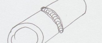
- Radial technique . This type of welding is often used for processing pipe structures. At the joint sections of the pipes there is a special ring, the rotation of which allows you to create the necessary temperature for joining the surfaces.
- Pin welding is often used in repairs . To do this, first create a hole into which a special pin is driven. After this, the part begins to rotate, thermal energy is generated, and plasticization of the coating occurs.
Friction stir welding
This method was developed and introduced in 1991.
Initially, this method was developed for aluminum and aluminum alloys, since during fusion welding most of the material was spent on the design of the weld, and the plastic properties of aluminum were also lost during fusion.
After implementation of the method and good results, it was found that the rotation stir welding method is suitable for a wide range of metals.
Main areas of application:
- shipbuilding, especially the submarine fleet, where completely sealed welded joints are required;
- construction of space objects and shuttles;
- storage facilities and tanks for storing cryogenic gases and liquids that have increased volatility.
The most unique products that are produced with elements of rotational welding are copper containers intended for storing waste from the nuclear industry.
Efficiency of the method
At first, friction welding is quite difficult, but gradually, as the aluminum and the nozzle acquire a suitable operating temperature, the process begins to go much easier. And if at first the nozzle moves sideways, then it will move smoothly, forming an even and beautiful seam. Upon completion of the work, it is clear that the metal has been welded externally, although on the inside the seam is not of sufficient quality.
When broken, the welded joint is very strong, but in the opposite direction it is very easy to tear it with your hands. The metal is not cooked deeply and therefore the inner layer does not melt or mix properly.
So we can conclude that welding aluminum with a drill is quite possible, but the result leaves much to be desired. Therefore, if you need to create a durable and high-quality result, it is better to use the classic method, which will definitely ensure a reliable seam and a strong structure at the end.
Features and applications
FSW is widely used in many areas of production. In aircraft rocket engineering, it is used to form fuselage structures or panels for various purposes. If we talk about shipbuilding, it is used for welding the hull of small ships. And that’s not all; such popularity is explained by the high quality of the resulting compound.
Interatomic bonds during welding can provide strength that is equal to or at a higher level than the base material. The quality of such seams usually withstands heavy loads and reliably serves for a long time.
Friction welding joins metals that are in a solid state. In this case, a special rotating tool is used; it consists of a collar, a profiled base and a tip with a profile; it moves along the joint of the workpieces being joined. Next, heat generation occurs followed by the joining of the material. The pressure of the collar at the joint promotes plastic deformation and flow of the welded metal, which is mixed with a profiled tip.
Process principle
Friction stir welding is carried out using a special tool that resembles the shape of a rod. Among the features of friction stir welding, the following points can be noted:
- The friction stir welding equipment used consists of two main parts: the shoulder and shoulder, as well as the tip.
- The tool is selected depending on the thickness of the material and its type. Some alloys are characterized by a low degree of machinability.
- The length of the tip is set depending on the thickness of the part.
- This welding method can be performed with filler material. At the time of welding, the tool rotates at high speed at the melting point. The applied pressure causes the tip to be inserted into the workpiece to the required thickness. In this case, the shoulder pad should touch the surface being treated.
- The next step is to move the tool along the seam line at a certain speed. With strong friction, the surface of the material begins to heat up greatly, due to which it begins to become plastic. The deformation occurs evenly.
Welding process
Using a special installation, you can create a strong connection that is characterized by fairly high quality.