GOST 14806-80 as amended. 1991 applies to welded joints made of aluminum and aluminum alloys with a thickness of the edges of the parts being welded 0.8...0.6 mm (Table 20)
Symbols of inert gas arc welding methods:
RINp - manual with a non-consumable electrode with filler metal;
AINl - automatic with a non-consumable electrode with filler metal;
AINp-3 - automatic with a non-consumable electrode with filler material - three-phase;
AIP - automatic consumable electrode - single-arc;
PIP - semi-automatic with a consumable electrode.
Fig.8
Preparation for welding
Copper or its alloys are cut into dimensional pieces using a grinding machine, pipe cutters, lathes and milling machines, as well as plasma arc cutting. Edges for welding are prepared mechanically. The parts to be welded and the filler wire are cleaned of oxides and contaminants to a metallic shine and degreased. The edges are treated with fine sandpaper, metal brushes, etc. The use of coarse abrasives is not recommended. It is possible to etch edges and wires in an acid solution:
75 cm3 per 1 liter of nitrogen water;
100 cm3 per 1 liter of sulfuric water;
1 cm3 per 1 liter of salt water
followed by washing in water and alkali and drying with hot air. Structures with a wall thickness of 10-15 mm are preheated with a gas flame, a dispersed arc and other methods. The assembly of joints of parts for welding is carried out either in fixtures or with the help of tacks. The gap between the joined workpieces is kept the same throughout. The tacks must have a minimum cross-section so that they can be remelted during the welding process. The surface of the tacks must be cleaned and ensured that there are no surface hot cracks.
If welding is carried out in the lower position, then special devices made of graphite or copper are used to improve heat removal
When welding in the open air, the joint is equipped with removable screens
1 - gas flow; 2 - seam; 3 - screen.
14806-80 and 14771-76
Standardization of direct welding technology for aluminum and aluminum products is reflected in the corresponding regulatory document. This includes connections of parts with edge thicknesses from 0.8 to 60 mm. Pipeline welding has slightly different requirements, so this standard does not apply to them.
GOST 14771-76, as stated earlier, has the same structure. The only difference is that the first document is defined specifically for aluminum-containing materials, and the second - for steels and alloys based on nickel and iron-nickel.
Checking welded joints for permeability
If welding is used in the manufacture of tanks, tightness control is required. To do this, tests for tightness of connections are carried out. Quality control is carried out using gases or liquids.
The essence of the method is based on creating a large pressure difference between the outer and inner areas of the container. With through-hole flaws in the weld, liquid or gas will flow from an area of high pressure to an area of low pressure.
Depending on the substance used and the method of obtaining excess pressure, permeability control is carried out by pneumatics, hydraulics or vacuum.
Pneumatic method
The use of a pneumatic welding quality control method requires pumping the tank with some gas to a pressure of 150% of the nominal pressure.
Then all welds are moistened with soapy water. Bubbles form in places of leakage, which is very easy to fix. For better visualization, an ammonia additive is used, and the seam is covered with a bandage soaked in phenolphthalein. Red spots appear in areas of leakage.
If it is not possible to pump up the container, then use the blowing method. On one side the seam is blown under a pressure of at least 2.5 atmospheres, and on the other it is coated with a soap solution. If there is a defect, it will appear in the form of bubbles.
Hydraulic method
With the hydraulic method of welding quality control, the container being tested is filled with water or oil. An excess pressure is created in the vessel, which is one and a half times more than the nominal pressure.
Then, for a certain time, usually 10 minutes, the area around the seam is tapped with a hammer with a rounded head. If there is a through welding defect, a leak will appear. If the excess pressure is small, then the holding time of the tank is increased to several hours.
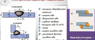
Geometric characteristics
As mentioned above, the geometry of the seams depends on the type of connection. The main geometric dimensions of the sections of butt and fillet welds are presented in the following figure:
Geometric characteristics
- where S is the thickness of the parts;
- e – width of the weld;
- g – convexity;
- m – concavity;
- h – penetration depth;
- t – weld thickness;
- b – gap in the connection;
- k – fillet weld leg;
- p – height;
- a – thickness.
The geometric dimensions are affected by the type of connection and the thickness of the products being welded. These indicators are shown in the following table.
Table with types of welded joints
From the information presented it is clear that all geometric dimensions of welds and parts being connected are interconnected. The length of these elements of welded structures stands out. It depends only on the load on the connection and is completely independent of the geometry of the seam section. The minimum length of the weld must ensure the strength of the connection when the maximum total load is exceeded by 20%. Products are often welded along the entire length of the contact, but in many cases welding is performed in short sections to ensure the necessary strength of the connection. For building structures, the calculation of the length of the weld according to SNiP II-23-81 is carried out based on these criteria.
Calculation of butt weld geometry
The method for checking seams for this type is fully described in the following regulatory documents: SNiP II-23-81 clause 11.1 and SP 16.13330.2011 clause 14.1.14. These documents present different calculation methods, but all of them are derived from the following mathematical formula:
Formula for calculating the geometry of a butt weld
- where N is the maximum tensile or compressive force;
- t – minimum thickness of welded parts;
- lw – seam length;
- Rwy – load resistance;
- γс – tabular coefficient.
With this type of connection, it is welded over the entire length of the contact, therefore the length of the seam is equal to the length of the joints of the parts being welded, reduced by 2t, twice the thickness of the metal. The width of the seam depends on the shape of the edges and the thickness of the parts. Schemes of design options for butt joints are shown in the following figures.
Design diagrams for butt joints
If during welding work materials are used in accordance with Appendix 2 of SNiP II-23-81, no calculations are made, only visual quality control of the connections made is carried out.
Calculation of fillet weld geometry
Calculation of the geometric dimensions of fillet welds under the influence of a load passing along the axis of the center of gravity is carried out along the selected section, the most dangerous in this connection. This may be a calculation based on the cross-section of the weld metal or the fusion boundaries of materials. The figure below shows both sections.
Fillet weld geometry diagram
In this type of welded joints, stresses of various types act, but the dominant load is the shear force. Fillet welds are checked using the following formulas.
Calculation formula for weld metal
Formula for calculating the fusion boundary
where N is the maximum tensile or compressive force; βf and βz – tabular coefficients for steel; kf – weld leg length; lw – length; Rwf – design shear resistance; Rwz – the same but in the fusion zone; γс – tabular coefficient of operating conditions; γwf and γwz – the same, but for different operating conditions.
The main geometric characteristic of all fillet welds is the size of their leg, i.e. the thickness along the fusion boundaries. The size of the leg depends on the thickness of the parts, material and welding method. You can select the value of this geometric parameter in the table below.
Table of minimum fillet weld legs
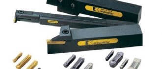
Tools for checking seam dimensions
A weld geometric parameters meter is a specialized tool that can be used to measure the main characteristics of these elements of welded structures. Among the variety of such measuring instruments, the following groups of products can be distinguished: templates, universal meters and devices specialized in measuring one parameter. A professional welder’s kit includes several such tools that allow you to measure both parts prepared for welding and the weld itself.
Conclusion
The above information is relevant for connections made using manual electric arc welding. The dimensions of the weld in semi-automatic welding are calculated using other methods. It should be noted that all geometric dimensions of welds are strictly tied to the thickness of the parts being welded and the maximum load that the entire structure must withstand!
We'll call you back in 30 seconds.
GOST R ISO 2553-2017 GOST R ISO 6947-2017 GOST R ISO 13920-2017 GOST R 55554-2013 GOST R ISO 6520-1-2012 GOST R ISO 14174-2010 GOST R ISO 14175-2010 GOST R EN 13479-201 0 GOST R EN 12074-2010 GOST R ISO 2560-2009 GOST R 53689-2009 GOST R ISO 3581-2009 GOST R ISO 3580-2009 GOST 10543-98 GOST 19249-73 GOST 21449-75 GOST 5264-80 GOST 9467- 75 GOST 21448 -75 GOST 23178-78 GOST 15164-78 GOST 14806-80 GOST 16038-80 GOST 9087-81 GOST 25445-82 GOST 26271-84 GOST 26101-84 GOST 27580-88 GOST 28915-91 GOST 2246-70 GOST 5.917-71 GOST 5.1215-72 GOST 10051-75 GOST 11533-75 GOST 10052-75 GOST 11534-75 GOST 7871-75 GOST 23518-79 GOST 14776-79 GOST 15878-79 GOST 16037-80 GOST 23949-80 GOST 26467-85 GOST 16130 -90 GOST 30430-96 GOST 30242-97 GOST 30482-97 GOST R 52222-2004 GOST 28555-90 GOST 30756-2001 GOST 14771-76 GOST 9466-75 GOST 8713-79
- gost-27580-88.pdf (681.67 KiB)
GOST 27580-88
GOST 27580−88 Group B05
STATE STANDARD OF THE UNION OF THE SSR ARC WELDING OF ALUMINUM AND ALUMINUM ALLOYS IN INERT GASES WELDED JOINTS AT ACUTE AND OBTUDE ANGLES. Basic types, structural elements and dimensions of Arc welding of aluminum and aluminum alloys in inert gases. Acute and blunt weld joints. Main types, design elements and dimensions
OKSTU 0072
Validity period from 01.01.89 to 01.01.94* ______________________________ * The validity period was lifted according to Protocol No. 3−93 of the Interstate Council for Standardization, Metrology and Certification. (IUS No. 5−6 1993). — Note "CODE".
INFORMATION DATA
1. APPROVED AND ENTERED INTO EFFECT by Resolution of the USSR State Committee on Standards dated January 18, 1988 N 67
2. INTRODUCED FOR THE FIRST TIME
3. REFERENCE REGULATIVE AND TECHNICAL DOCUMENTS:
| Designation of the referenced technical document | Item number |
| GOST 2789−73 | 5 |
1. This standard applies to welded joints made of aluminum and aluminum alloys with a thickness of the edges of the welded parts from 0.8 to 60.0 mm inclusive and establishes the main types of welded joints, structural elements and dimensions of the edges and welds made by arc welding in inert gases The standard does not apply to welded connections of pipelines.
2. The standard adopts the following symbols for arc welding methods in inert gases: RIN - manual non-consumable electrode with filler metal; AIN - automatic non-consumable electrode with filler metal; AIN - automatic non-consumable electrode with filler metal - three-phase; AIP - automatic consumable electrode - single-arc; PIP - semi-automatic with consumable electrode.
3. The main types of welded joints must correspond to those indicated in the table. 1.
4. Structural elements and their dimensions must correspond to those indicated in the table. 2−19.
Table 1
| Connection type | Shape of prepared edges | Character of the weld | Cross-sectional shape of prepared edges and completed seam | Thickness of welded parts, mm, for welding methods | Angle of connection of parts | Symbol for connection | ||||
| RIN | AIN | AIN | PIP | AIP | opinions | |||||
| No beveled edges | One-sided | 0,8−6,0 | 0,8−6,0 | — | 4−12 | 4−12 | 179°- 122° | U1 | ||
| 0,8−20,0 | 0,8−20,0 | — | 4−12 | 4−12 | 121°-91°; 89°-31° | |||||
| 0,8−12,0 | 0,8−12,0 | — | 4−12 | 4−12 | 30°-5° | |||||
| Angular | One-sided lined | 0,8−5,0 | 0,8−16,0 | 5−25 | 3−12 | 3−12 | 179°- 136° | U2 | ||
| No beveled edges | Double-sided | 2,0−6,0 | 2,0−10,0 | 10−30 | 4−8 | 4−12 | 179°-91° | U3 | ||
| 2,0−6,0 | 2,0−6,0 | — | 4−12 | 4−12 | 89°-60° | |||||
| With one edge beveled | One-sided | 4,0−20,0 | — | — | 6,0−20,0 | — | 179°-122° | U4 | ||
| 4,0−20,0 | 4,0−20,0 | — | 4,0−20,0 | 4,0−20,0 | 89°-32° | |||||
| Angular | Double-sided | 4−20 | — | — | 6−20 | — | 179°-122° | U5 | ||
| 4−20 | 4−20 | — | 4−20 | 4−20 | 89°-60° | |||||
| With two bevels on one edge | Double-sided | 12−35 | — | — | 12−35 | — | 179°- 165°; 89°-75° | U6 | ||
| Angular | With one edge beveled | One-sided lined | 4−20 | — | — | 6−20 | — | 179°- 136° | U7 | |
| With two bevels on one edge and one bevel on the second edge | Double-sided | 12−30 | 12−30 | 32−60 | 12−30 | 12−30 | 179°- 136° | U8 | ||
| With two beveled edges | One-sided | 4−20 | 8−20 | — | 10−30 | 10−30 | 179°- 122° | U9 | ||
| 12−30 | 12−30 | — | 12- 30 | 12−30 | 89°- 61° | |||||
| Angular | Double-sided | 4−20 | 4−40 | 20−40 | 10- 30 | 10−30 | 179°- 122° | U10 | ||
| 12−30 | 12−30 | — | 12−30 | 12−30 | 89°-61° | |||||
| No beveled edges | One-sided | 1−20 | 2−20 | 3−20 | 3−20 | 3−20 | 91°-179° | T1 | ||
| Tavrovoe | Double-sided | 1−20 | 2−30 | 3−20 | 3−20 | 3−20 | 91°-120° 89°-60° | T2 | ||
| With one edge beveled | One-sided | 4−20 | 4−20 | — | 4−20 | 4−20 | 91°-149° | T3 | ||
| With one edge beveled | Double-sided | 4−20 | 4−20 | — | 4−20 | 4−20 | 91°-149° | T4 | ||
| Tavrovoe | One-sided | 4−20 | 4−20 | — | 4−20 | 4−20 | 89°-59° 91°-121° | T5 | ||
| Double-sided | 4−20 | 4−20 | — | 4−20 | 4−20 | 89°-59° 91°-121° | T6 | |||
| With two bevels on one edge | 12−35 | 12−35 | — | 12−35 | 12−35 | 91°-100° 89°-80° | T7 | |||
| Tavrovoe | With two curved bevels on one edge | Double-sided | 32−60 | — | — | 32−60 | — | 91°-105° 89°-75° | T9 | |
table 2
Dimensions, mm
| Designation | Structural elements | Welding method | s | b | e, no more | n | |||||||
| connection | prepared edges to be welded | weld | No-min. | Prev. off | at | No-min. | Prev. off | ||||||
| nia | details | 179°-122° | 121°-91° | 89°-31° | 30°-5° | ||||||||
| RIN; AIN | From 0.8 to 2.5 | +0,5 | 0,8 | ||||||||||
| St. 2.5 to 6.0 | 2s+5 | 1,0 | ±0,5 | ||||||||||
| St. 6.0 to 10.0 | +1,0 | 2s+4 | — | ||||||||||
| U1 | St. 10.0 to 12.0 | 0 | — | 2s+6 | 2s+5 | 2,0 | ±1,0 | ||||||
| St. 12.0 to 20.0 | +2,0 | — | |||||||||||
| AIP; PIP | From 4.0 to 10.0 | +1,0 | 0 to 0.5s | ||||||||||
| St. 10.0 to 12.0 | +2,0 | 2s+5 | 2s+4 | 1 | +2,0 | ||||||||
Table 3
Dimensions, mm
| Designation | Structural elements | Welding method | s | h, no less | b | e, no more | |||||
| connection | prepared edges of welded parts | weld | No-min. | Prev. off | at | No-min. | Prev. off | ||||
| 179°-160° | 159°-136° | ||||||||||
| From 0.8 to 1.0 | 0 | ±1,5 | 2s+5 | 2s+7 | 0,8 | ||||||
| RIN; AIN | St. 1.0 to 2.0 | 1 | ±0,5 | ||||||||
| St. 2.0 to 5.0 | 1 | ±1,0 | 1,0 | ||||||||
| AIN; AIN | From 5.0 to 16.0 | 3 | ±1,5 | s+6 | 2,0 | ||||||
| U2 | St. 16.0 to 18.0 | 3,0 | |||||||||
| AIN | St. 18.0 to 22.0 | 1,5 | 4,0 | ±1,0 | |||||||
| St. 22.0 to 25.0 | 4,5 | ||||||||||
| AIP; PIP | From 3.0 to 12.0 | ±1,0 | 2,0 | ||||||||
Table 4
Dimensions, mm
| Designation | Structural elements | Welding method | s | e, no more | ±2 | b | |||||||
| connection | prepared edges to be welded | weld | at | No-min. | Prev. off | No-min. | Prev. off | ||||||
| details | 179°-150° | 149°-91° | 89°-60° | 179°-91° | 89°-60° | ||||||||
| RIN; AIN | From 2 to 3 | s+3 | s+4 | 5 | |||||||||
| St. 3 to 6 | s+6 | s+7 | s+4 | 3 | +1 | 1 | ±0,5 | ||||||
| St. 6 to 8 | +7 | +8 | 10 | ||||||||||
| AIN | St. 8 to 10 | ||||||||||||
| From 10 to 14 | s+8 | s+10 | |||||||||||
| St. 14 to 18 | s+5 | s+6 | — | 4 | 2 | ±1,0 | |||||||
| U3 | AIN | St. 18 to 20 | 13 | 0 | +2 | ||||||||
| St. 20 to 24 | s+3 | s+4 | |||||||||||
| St. 24 to 30 | s | s+2 | 5 | ||||||||||
| AIP; PIP | From 4 to 6 | 1 | ±0,5 | ||||||||||
| St. 6 to 8 | 3 | ||||||||||||
| St. 8 to 10 | s+6 | s+8 | s+6 | 10 | 4 | +1 | 2 | ±1,0 | |||||
| AIP | St. 10 to 12 | ||||||||||||
| PIP | From 8 to 12 | — | |||||||||||
Table 5
Dimensions, mm
| Designation | Structural elements | Welding method | s | e, no more | c | b | ||||||||
| connection | prepared edges to be welded | weld | at | No-min. | Prev. off | No-min. | Prev. off | No-min. | Prev. off | |||||
| details | 179°- 122° | 89°- 32° | St. 90° | Up to 90° | ||||||||||
| From 4 to 6 | 2 | |||||||||||||
| RIN; | St. 6 to 10 | 1.6s+7 | 1.5s+8 | +1 | 2 | |||||||||
| St. 10 to 14 | 3 | ±1 | ||||||||||||
| St. 14 to 20 | 1.6s+10 | 1.6s+5 | +2 | 3 | ±1 | |||||||||
| From 4 to 6 | — | |||||||||||||
| St. 6 to 8 | 1.4s+6 | 4 | +1 | 2 | ||||||||||
| U4 | St. 8 to 10 | 1.4s+6 | 0 | 60° | ||||||||||
| PIP | St. 10 to 12 | ±2 | ||||||||||||
| St. 12 to 14 | 1.6s+7 | 1.6s+7 | ||||||||||||
| St. 14 to 20 | 5 | +2 | 4 | ±2 | ||||||||||
| From 4 to 10 | 1.5s+8 | |||||||||||||
| AIN; AIP | St. 10 to 20 | — | 1.6s+5 | |||||||||||
Table 6
Dimensions, mm
| Designation | Structural elements | Welding method | s | e, no more | e±2 | c | b | ±1° | |||||||||
| connection | prepared edges to be welded | weld | at | No-min. | Prev. off | No-min. | Prev. off | No-min. | Prev. off | ||||||||
| details | 179°- 122° | 89°- 60° | St. 90° | Up to 90° | St. 90° | Up to 90° | |||||||||||
| RIN | From 4 to 6 | 1.5s+6 | 1.5s+8 | 3 | |||||||||||||
| St. 6 to 8 | 2 | +1 | 2 | ||||||||||||||
| St. 8 to 10 | 1.5s+8 | 10 | +1 | ||||||||||||||
| U5 | St. 10 to 12 | 1.6s+10 | 1.6s+5 | 4 | |||||||||||||
| St. 12 to 20 | 13 | 3 | 0 | +2 | 3 | +1 | 60° | ||||||||||
| PIP | From 4 to 6 | — | 1.4s+6 | 3 | +1 | 2 | |||||||||||
| From 6 to 10 | 1.4s+6 | 10 | 4 | ±2 | |||||||||||||
| St. 10 to 14 | 1.6s+7 | 4 | |||||||||||||||
| St. 14 to 20 | 1.6s+7 | 13 | 5 | 5 | +2 | 4 | ±2 | ||||||||||
| AIN; | From 4 to 8 | 1.5s+8 | 3 | 2 | +1 | ||||||||||||
| AIP | St. 8 to 10 | — | — | ±1 | 2 | ±1 | |||||||||||
| St. 10 to 20 | 1.6s+7 | 4 | 3 | +2 | 3 | ||||||||||||
Table 7
Dimensions, mm
| Designation | Structural elements | Welding method | s | e=e | e | e | b | s ±1 | h ±1 | ±1° | ||||||||||||||
| tion | no more | at | ||||||||||||||||||||||
| connections | prepared edges to be welded | weld | at | St. 90° | up to 90° | |||||||||||||||||||
| details | 179°- 175° | 89°- 85° | 174°- 170° | 84°- 80° | 169°- 165° | 79°- 75° | 174°- 170° | 84°- 80° | 169°- 165° | 79°- 75° | St. 90° | Up to 90° | No-min. | Prev. off | No-min. | Prev. off | No-min. | Prev. off | ||||||
| RIN | From 12 to 14 | 2 | 5 | |||||||||||||||||||||
| St. 14 to 16 | 2 | 6 | ||||||||||||||||||||||
| St. 16 to 18 | s+2 | 5 | ±2 | 7 | ||||||||||||||||||||
| U6 | St. 18 to 20 | 1.1s+5 | 0.9s+6 | 0.8s+5 | 0.9s+10 | 1.2s+8 | ° | ° | ° | ° | 3 | ±1 | 0 | +2 | 8 | 60° | ||||||||
| St. 20 to 22 | 9 | |||||||||||||||||||||||
| St. 22 to 24 | s+3 | 4 | 10 | ±3 | 10 | |||||||||||||||||||
| RIN | St. 24 to 26 | 11 | ||||||||||||||||||||||
| St. 26 to 28 | s+3 | 12 | ||||||||||||||||||||||
| St. 28 to 30 | 1.1s+5 | 0.9s+6 | 0.8s+5 | 0.8s+5 | 0.9s+10 | 1.2s+8 | ° | ° | ° | ° | 4 | ±1 | 10 | 2 | 13 | 60° | ||||||||
| U6 | St. 30 to 32 | ±3 | 0 | +2 | 14 | |||||||||||||||||||
| St. 32 to 35 | s+4 | 15 | ||||||||||||||||||||||
| PIP | From 12 to 14 | s+2 | +1 -2 | 6 | 4 | 4 | ||||||||||||||||||
| St. 14 to 16 | 5 | |||||||||||||||||||||||
| St. 16 to 18 | s+2 | 4 | 6 | |||||||||||||||||||||
| St. 18 to 20 | +1 -2 | 6 | ±3 | 0 | +2 | 4 | 7 | 60° | ||||||||||||||||
| St. 20 to 22 | 0.9s+6 | 0.8s+5 | 0.9s+10 | 1.2s+8 | ° | ° | ° | ° | 8 | |||||||||||||||
| St. 22 to 24 | s | 9 | ||||||||||||||||||||||
| St. 24 to 26 | 5 | 10 | ±4 | 10 | ||||||||||||||||||||
| PIP | St. 26 to 28 | 5 | 11 | |||||||||||||||||||||
| U6 | St. 28 to 30 | +1 -2 | 10 | +4 | 0 | +2 | 4 | 12 | 60° | |||||||||||||||
| St. 30 to 32 | s | 0.9s+6 | 0.8s+5 | 0.9s+10 | 1.2s+8 | ° | ° | ° | ° | 13 | ||||||||||||||
| St. 32 to 35 | 14 | |||||||||||||||||||||||
Table 8
Dimensions, mm
| Designation | Structural elements | Welding method | s | yeah, no more | With | b | ±1° | |||||
| connection | prepared edges of welded parts | weld | at 179°-136° | No-min. | Prev. off | No-min. | Prev. off | No-min. | Prev. off | |||
| RIN | From 4 to 10 | 1.6s+7 | 2 | +1 | ||||||||
| St. 10 to 12 | ±1 | 2 | ||||||||||
| St. 12 to 20 | 1.6s+10 | 3 | +2 | 3 | ±1 | |||||||
| U7 | PIP | From 6 to 10 | 1.4s+6 | ° | 4 | 0 | +1 | 60° | ||||
| St. 10 to 14 | 1.6s+7 | 5 | ±2 | 2 | ||||||||
| St. 14 to 20 | +2 | 4 | ±2 | |||||||||
Table 9
Dimensions, mm
| Designation | Structural elements | Welding method | s | h=h±1.5 | e=e ±3 | ||||
| connections | prepared edges of welded parts | weld | at179°-136° | No-min. | Prev. off | s ±1 | ±1° | ||
| RIN; AIN | From 12 to 14 | 5 | s+5 | ||||||
| St. 14 to 17 | 7 | 3 | 3 | ||||||
| St. 17 to 20 | 9 | ||||||||
| St. 20 to 23 | 10 | 0.9s+5 | ±1 | ||||||
| U8 | St. 23 to 26 | 11 | ° | ° | 70° | ||||
| St. 26 to 30 | 13 | 0.8s+5 | 4 | 12 | |||||
| AIN | From 32 to 36 | 11 | |||||||
| From 36 to 40 | 13 | 0.6s+3 | +1 -2 | ||||||
| St. 40 to 44 | 15 | ||||||||
| St. 44 to 48 | 17 | ||||||||
| St. 48 to 52 | 19 | ||||||||
| St. 52 to 56 | 21 | 0.6s+5 | |||||||
| St. 56 to 60 | 23 | ||||||||
| U8 | AIP; PIP | From 12 to 14 | 4 | 5 | |||||
| St. 14 to 17 | 6 | ||||||||
| St. 17 to 20 | 8 | 0.8s+3 | |||||||
| St. 20 to 23 | 9 | 8 | |||||||
| St. 23 to 26 | 10 | 0.7s+4 | 5 | ||||||
| St. 26 to 30 | 12 | ||||||||
Table 10
Dimensions, mm
| Designation | Structural elements | Welding method | s | e, no more | s ±1 | b | ±1° | ||||||||
| connection | prepared edges to be welded | weld | at | No-min. | Prev. off | No-min. | Prev. off | ||||||||
| details | 179°- 142° | 141°- 122° | 89°- 61° | St. 90° | Up to 90° | ||||||||||
| RIN | From 4 to 8 | 1.4s+5 | +1 | 2 | |||||||||||
| RIN; AIN | St. 8 to 12 | — | |||||||||||||
| St. 12 to 14 | 1.5s+7 | 2 | ±1 | ||||||||||||
| St. 14 to 20 | 1.5s+5 | 1.5s+6 | 3 | ||||||||||||
| From 20 to 30 | — | ||||||||||||||
| U9 | AIP; PIP | From 10 to 12 | — | 0 | 35° | ||||||||||
| St. 12 to 22 | 1.3s+3 | 1.4s+3 | 4 | ||||||||||||
| St. 22 to 24 | 1.4s+4 | 4 | +2 | ||||||||||||
| St. 24 to 26 | 1.4s+3 | 1.5s+4 | +1 -2 | ||||||||||||
| St. 26 to 30 | 1.5s+3 | 5 | 5 | ||||||||||||
Table 11
Dimensions, mm
| Designation | Structural elements | Welding method | s | e, no more | e±2 | b | s ±1 | ±1° | |||||||||
| tion connections | at | ||||||||||||||||
| prepared edges of welded parts | weld | 179°- 142° | 141°- 122° | 89°- 61° | St. 90° | Up to 90° | St. 90° | Up to 90° | No-min. | Prev. off | No-min. | Prev. off | |||||
| RIN; AIN | From 4 to 8 | 1.4s+5 | |||||||||||||||
| St. 8 to 10 | — | 10 | +1 | 2 | 2 | ||||||||||||
| St. 10 to 12 | 1.5s+7 | ||||||||||||||||
| St. 12 to 14 | 3 | ||||||||||||||||
| St. 14 to 20 | 1.5s+5 | 1.5s+6 | 14 | 3 | |||||||||||||
| St. 20 to 30 | — | 4 | |||||||||||||||
| AIN; AIN | From 20 to 24 | ||||||||||||||||
| U10 | St. 24 to 26 | 1.5s+4 | — | 5 | 0 | 12 | 5 | +1 | 35° | ||||||||
| St. 26 to 40 | — | +2 | |||||||||||||||
| AIP; PIP | From 10 to 12 | 1.5s+2 | 1.5s+2 | 3 | |||||||||||||
| St. 12 to 14 | 1.5s+4 | 15 | 5 | 4 | |||||||||||||
| St. 14 to 24 | |||||||||||||||||
| St. 24 to 26 | 1.4s+2 | 1.5s+2 | 8 | ||||||||||||||
| St. 26 to 30 | 1.5s+3 | 5 | |||||||||||||||
Table 12
Dimensions, mm
| Designation | Structural elements | Welding method | s | yeah, no more | , no less | b | |||||||
| connection | at | No-min. | Prev. off | ||||||||||
| prepared edges of welded parts | weld | 91°- 100° | 101°- 110° | 111°- 120° | 121°- 135° | 136°- 179° | 179°- 136° | 135°- 91° | |||||
| RIN | From 1 to 2 | s+b | +0,5 | ||||||||||
| RIN; AIN | St. 2 to 3 | 5 | 7 | 3 | |||||||||
| St. 3 to 4 | +1,0 | ||||||||||||
| RIN; | St. 3 to 8 | 7 | 4 | 0 | |||||||||
| T1 | AIN; AIN | St. 8 to 12 | 10 | 9 | 6 | 0.5s | |||||||
| AIP; PIP | St. 12 to 16 | 0.9s+b | s+b | 1.1s+b | 1.2s+b | +2,0 | |||||||
| St. 16 to 20 | 13 | 8 | |||||||||||
Table 13
Dimensions, mm
| Designation | Structural elements | Welding method | s | yeah, no more | e, no less | , no less | b | ||||||||
| connection | prepared edges to be welded | weld | at | No-min. | Prev. off | No-min. | Prev. off | ||||||||
| details | 91°- 100° | 89°-80° | 101°- 110° | 79°-70° | 111°- 120° | 68°-60° | |||||||||
| RIN | From 1 to 2 | +0,5 | |||||||||||||
| RIN; AIN | St. 2 to 3 | 5 | 7 | 3 | 3 | +2 | |||||||||
| St. 3 to 4 | +1,0 | ||||||||||||||
| RIN; AIN; | From 3 to 8 | 7 | 9 | 4 | 4 | +3 | 0 | ||||||||
| T2 | AIN; AIP; PIP | St. 8 to 12 | |||||||||||||
| St. 12 to 16 | 10 | 6 | 6 | +4 | +2,0 | ||||||||||
| St. 16 to 20 | 13 | 0.9s+b | s+b | 8 | 8 | +5 | |||||||||
Table 14
Dimensions, mm
| Designation | Structural elements | Welding method | s | yeah, no more | b | s ±1 | ±1° | ||
| connection | prepared edges of welded parts | weld | at 91°-149° | No-min. | Prev. off | ||||
| RIN | From 4 to 10 | +1 | 2 | ||||||
| St. 10 to 20 | 1.5s+6 | +2 | |||||||
| T3 | AIP; PIP | From 4 to 10 | 0 | +1 | 3 | 5±3 | 60° | ||
| St. 10 to 14 | 1.5s+4 | ||||||||
| St. 14 to 20 | +2 | 5 | |||||||
Table 15
Dimensions, mm
| Designation | Structural elements | Welding method | s | yeah, no more | e | b | s ±1 | ±1° | |||
| connection | prepared edges of welded parts | weld | at 91°-149° | No-min. | Prev. off | No-min. | Prev. off | ||||
| RIN; AIN | From 4 to 6 | 3 | |||||||||
| St. 6 to 8 | +3 | +1 | 2 | ||||||||
| St. 8 to 10 | 4 | ||||||||||
| St. 10 to 12 | 1.5s+6 | +4 | |||||||||
| St. 12 to 18 | +2 | ||||||||||
| T4 | St. 18 to 20 | 5 | +5 | 5±3 | 60° | ||||||
| AIP; PIP | From 4 to 6 | 3 | 0 | 3 | |||||||
| St. 6 to 8 | +3 | +1 | |||||||||
| St. 8 to 10 | 4 | ||||||||||
| St. 10 to 12 | 1.5s+4 | ||||||||||
| St. 12 to 14 | +4 | ||||||||||
| St. 14 to 18 | 5 | +2 | |||||||||
| St. 18 to 20 | +5 | 5 | |||||||||
Table 16
Dimensions, mm
| Designation | Structural elements | Welding method | s | e= | b | |||||||
| connection | prepared edges to be welded | weld | Nom. | Prev. off | No-min. | Prev. off | ||||||
| details | at | |||||||||||
| 89°-59° | 91°-121° | 89°-59° | 91°-121° | St. 90° | Up to 90° | |||||||
| From 4 to 6 | 3 | +3 | ||||||||||
| St. 6 to 10 | 7 | ±2 | +1 | |||||||||
| RIN; AIN | St. 10 to 12 | 4 | +4 | |||||||||
| St. 12 to 18 | 10 | ±3 | +2 | |||||||||
| T5 | St. 18 to 20 | 5 | 13 | +5 | ||||||||
| AIP; PIP | From 4 to 6 | 3 | 0 | |||||||||
| St. 6 to 8 | 6 | +3 | ±2 | +1 | ||||||||
| St. 8 to 10 | 4 | |||||||||||
| St. 10 to 12 | ||||||||||||
| St. 12 to 14 | 8 | +4 | ||||||||||
| St. 14 to 18 | 5 | ±3 | +2 | |||||||||
| St. 18 to 20 | 9 | +5 | ||||||||||
Table 17
Dimensions, mm
| Designation | Structural elements | Welding method | s | e= | b | |||||||
| connection | prepared edges to be welded | weld | Nom. | Prev. off | No-min. | Prev. off | ||||||
| details | at | |||||||||||
| 89°-59° | 91°-121° | 89°-59° | 91°-121° | St. 90° | Up to 90° | |||||||
| From 4 to 6 | 3 | +3 | ||||||||||
| St. 4 to 10 | 4 | 7 | ±2 | +1 | ||||||||
| RIN; AIN | St. 10 to 12 | 10 | +4 | |||||||||
| St. 12 to 18 | 5 | ±3 | +2 | |||||||||
| St. 18 to 20 | 13 | +5 | ||||||||||
| T6 | From 4 to 6 | 3 | 0 | |||||||||
| From 6 to 8 | 6 | +3 | ±2 | +1 | ||||||||
| From 8 to 10 | 4 | |||||||||||
| AIP; PIP | St. 10 to 12 | +4 | ||||||||||
| St. 12 to 18 | 9 | ±3 | +2 | |||||||||
| St. 18 to 20 | 5 | 10 | +5 | |||||||||
Table 18
Dimensions, mm
| Designation | Structural elements | Welding method | s | h | e=e | e | e | b | s ±1 | ±1° | |||||||
| connections | no more | No-min. | Prev. off | ||||||||||||||
| prepared edges to be welded | weld | at | |||||||||||||||
| details | 91°-95° | 89°-85° | 96°- 100° | 84°-80° | 96°- 100° | 84°-80° | St. 90° | Up to 90° | |||||||||
| From 12 to 14 | 5 | 1.4s+5 | |||||||||||||||
| St. 14 to 17 | 7 | 1.1s+4 | 1.1s+5 | 1.2s+4 | |||||||||||||
| St. 17 to 20 | 9 | ||||||||||||||||
| T7 | RIN; AIP | St. 20 to 23 | 11 | ||||||||||||||
| St. 23 to 26 | 12 | 1.1s+2 | 1.2s+6 | 1.2s+6 | 0 | +2 | 3 | 5±3 | 60° | ||||||||
| St. 26 to 30 | 13 | ||||||||||||||||
| St. 30 to 35 | 15 | s+3 | |||||||||||||||
| From 12 to 14 | 4 | 1.4s+3 | 1.2s+3 | ||||||||||||||
| St. 14 to 17 | 6 | 1.1s+3 | |||||||||||||||
| St. 17 to 20 | 8 | ||||||||||||||||
| AIP; PIP | St. 20 to 23 | 10 | 1.1s | ||||||||||||||
| St. 23 to 26 | 12 | 1.1s | s+4 | 0 | +2 | 4 | 5±3 | 60° | |||||||||
| St. 26 to 30 | 14 | ||||||||||||||||
| St. 30 to 35 | 16 | s+2 | s | ||||||||||||||
Table 19
Dimensions, mm
| Designation | Structural elements | Welding method | s | h ±1.5 | e=e ±3 | b | s ±1 | ±1° | |||||||
| connections | at | ||||||||||||||
| prepared edges of welded parts | weld | 91°-105° | 89°-75° | St. 90° | Up to 90° | No-min. | Prev. off | No-min. | Prev. off | ||||||
| RIN | From 32 to 36 | 15 | 0.7s | ||||||||||||
| St. 36 to 40 | 17 | ||||||||||||||
| St. 40 to 44 | 19 | ||||||||||||||
| T9 | St. 44 to 48 | 21 | |||||||||||||
| St. 48 to 52 | 23 | 0.6s | 0 | +2 | 5 | ±3 | 3 | 30° | |||||||
| St. 52 to 56 | 25 | ||||||||||||||
| St. 56 to 60 | 27 | ||||||||||||||
| PIP | From 32 to 36 | 14 | 0.7s | ||||||||||||
| St. 36 to 40 | 16 | ||||||||||||||
| St. 40 to 44 | 18 | ||||||||||||||
| T9 | St. 44 to 48 | 20 | |||||||||||||
| St. 48 to 52 | 22 | 0.6s | 0 | +2 | 5 | ±3 | 4 | 30° | |||||||
| St. 52 to 56 | 24 | ||||||||||||||
| St. 56 to 60 | 26 | ||||||||||||||
5. The edges of the parts to be welded must be processed mechanically, and the roughness of the treated surface must be no more than Rz 40 µm according to GOST 2789–73.
6. Welding joints of parts of unequal thickness with a difference not exceeding the values indicated in the table. 20, should be done in the same way as for parts of the same thickness. The structural elements of the prepared edges and the dimensions of the weld should be selected according to their greater thickness.
Table 20
mm
| Thickness of thin part | Part thickness difference |
| From 0.8 to 3.0 | 0,5 |
| St. 3.0 "5.0 | 1,0 |
| » 5,0 «12,0 | 1,2 |
| » 12,0 «25,0 | 1,5 |
| » 25,0 «60,0 | 3,0 |
If the difference in the thickness of the parts being welded exceeds the values indicated in the table. 20 on a part with a large thickness s, a bevel must be made on one or both sides to the thickness of the thin part s, as indicated in Fig. 1 and 2.
| Crap. 1 | Crap. 2 |
In this case, the structural elements of the prepared edges and the dimensions of the weld should be selected based on their smaller thickness.
7. In connections with a connection angle of 179°-91° without bevel of the edges of parts with a thickness of over 6 mm, when welding with a non-consumable electrode with filler metal, to ensure the direction of its supply into the weld pool, it is allowed to chamfer the upper edges of parts of size 1.0−1.5 mm45°.
8. When welding in positions other than the bottom, an increase in the size of the seam is allowed, but not more than 2 mm for parts up to 25 mm thick, 3 mm for parts over 25 mm.
9. When welding in helium with direct current, the weld dimensions can be reduced by up to 15%.
10. For design fillet welds, values of legs K; Kmust be established when designing a welded joint.
11. Maximum deviations of the leg values of design welds must correspond to:
+2.0 mm at K<5 mm; +3.0 mm at 5K8 mm; +4.0 mm at K>8 mm.
12. The dimensions of the seams made in the overlap area for closed joints, as well as in places corrected by welding, may differ from those established by this standard. In this case, they must comply with regulatory and technical documentation.
13. When welding technical aluminum, it is allowed to increase the size of the seams up to 20%.
14. When making a double-sided weld with full penetration, before welding on the reverse side, the root of the weld must be cleared to bare metal. Cleaning with abrasive wheels is not permitted.
15. With a variable angle of mating of parts, the seam is divided into sections. Each section of mating elements is made in accordance with the requirements of this standard.
Appearance - welded seams
| External defects in welds. |
The appearance of the welds must satisfy the following requirements.
The appearance of welds made by contact welding must meet the following requirements: for pipes with a wall thickness of up to 10 mm, there must be a uniform reinforcement around the circumference of the joint with a height of 3 to 5 mm; for pipes with a wall thickness above 10 mm, the reinforcement should be from 4 to 5 mm 6 mm.
The appearance of the welds must satisfy the following requirements: the shape and dimensions of the seam must comply with GOST 16037 - 80; the surface of the seam should be finely scaly; sponginess, porosity, rough scaliness are not allowed; the transition from the deposited metal to the base metal should be smooth; There should be no craters left on the seams.
The appearance of welds made by arc welding must meet the following requirements: The surface of the seams must be slightly convex and smooth (for manual welding - finely scaly); sponginess, porosity, rough scaliness are not allowed. The transition from the deposited metal to the base metal should be smooth. The seams should not have cracks, burns, craters or undercuts with a depth of more than 0 5 mm.
You should pay attention to the appearance of the welds of low-alloy steel connections: the seams should be finely flaky, without sharp transitions to the base metal; the craters are carefully welded; There should be no surface inclusions and the presence of undercuts is undesirable, even within acceptable standards.
After welding, the geometric dimensions of the product, the dimensions and appearance of the welds are controlled. In accordance with the requirements of the technical specifications for the product, welds are controlled by penetrating radiation or ultrasound (see chapter. All pressure vessels are tested for strength by hydraulic testing at a pressure exceeding the operating pressure.
| Sections of welds c.| Dependence of viscosity of slag fluxes on temperature. |
In conclusion, it should be noted that not only the appearance of welds, but also the number of defects in them depends on the forming ability of the flux. Indeed, a change in the cross-sectional shape of the seam means a corresponding change in the direction of growth of columnar crystallites and their location relative to the forces acting on the crystallizing seam.
| Diagram of a manipulator designed by Sabirov. |
It is necessary to observe the size of the gaps at the joints of welded joints, monitor the correct joining of adjacent petals, check the appearance of welded joints and the presence of undercuts, lack of fusion, cracks and other external defects, carry out mechanical tests of welded joints and their transmission with radioactive substances. Strict adherence to the accepted welding technology, high quality filler materials and fluxes, together with operational control methods, make it possible to obtain guaranteed high quality welds.
The use of this welding process is especially effective when increased demands are placed on the appearance of the welds. Rutile-fluorite wire (PP-AN4, PP-AN9, PP-AN20, PP-AN22, PP-AN54) is recommended for welding structures operating in difficult climatic conditions, at negative temperatures, dynamic and alternating loads. It is advisable to carry out welding work indoors; Welding in open areas is possible provided measures are taken to prevent the shielding gas from being blown off. When welding with a consumable electrode, the stick-out of the electrode is the distance from the end of the electrode wire to the cut of the current-carrying nozzle.
Modern technology makes it possible to obtain welds using electric arc welding that are not inferior in strength to the base metal. When welding with submerged arc or high-quality electrodes, you can obtain welds that do not have any defects. However, for a variety of reasons, defects occur in welds that reduce strength and spoil the appearance of welds and joints.
| Plastic welding diagram. |
A sign of proper heating of the parts being welded and the filler rod is the appearance of a wet sheen on their surface. In this case, the thin surface layer softens to a soft-flowing state. When the rod is pressed, the heated layers stick together and are partially squeezed out on the sides, and the rod forms a kind of roller. Sequentially, laying roller rods, fill the seam to the required section. In Fig. 147 shows types of filling of seams, and in Fig. 148 - appearance of welds.
Specifications and standards
Some types of work, goods and services are controlled by the state in terms of quality. The reason for such control was the inter-industry significance. State standards (GOST) contain a list of requirements for each product, for each result of activity that is subject to standardization. This is a document based on international standards and taking into account best practices, as well as all the achievements of science and technology. Standardization was introduced during the existence of the USSR. Standards cannot be static, so they change over time.
GOSTs in Russia are mandatory only for defense products, but in construction they are of great practical importance, because the main design indicators are safety and reliability. Some people confuse the state standard with technical specifications. In fact, specifications regulate the production of those goods that are not subject to standardization according to GOST. We can say that technical specifications are the result of the development of entrepreneurs who are producers. Although the TU is not a guest document, they do not contradict the state document, but, on the contrary, complement it.
In some sources, upon request, you can find only one document. However, it does not fully reflect all the standards relating to argon arc welding, its preparation and implementation. The list of all regulatory documents contains GOSTs adopted at different times. To date, there are 9 documents.
- GOST 5.917-71 defines the requirements for hand-held burners RGA-150 and RGA-400.
- GOST 14806-80 contains information on the parameters of argon arc welding of alloys containing aluminum.
- GOST 14771-76 is similar in structure to the previous document. Only here we are talking about gas-shielded arc welding as a generalized process.
- GOST 7871-75 defines the parameters of aluminum welding wire for TIG welding.
- GOST 2246-70 is a document that specifies the requirements for steel wire.
- GOST 23949-80 is a standard applied to tungsten electrodes for argon arc welding.
- GOST 18130-79 and GOST 13821-77 regulate the operation of equipment, including semi-automatic devices and rectifiers.
- GOST 10157-79 defines the standard for the most inert gas (argon).
Welding a fixed vertical joint
The weld is performed in two steps. The perimeter of the joint is conventionally divided by the vertical center line into two sections, each of which has three characteristic positions:
- ceiling (positions 1-3);
- vertical (positions 4-8);
- lower (positions 9-11).
Each section is welded from the ceiling position. Welding is carried out only with a short arc:
lmin=0.5 de, mm, where de is the diameter of the electrode.
Finish the seam in the lower position.
Welding of each section begins with a displacement of 10-20 mm from the vertical axial. The area where the seams overlap—the “lock” connection—depends on the diameter of the pipe and can be from 20 to 40 mm. The larger the pipe diameter, the longer the “lock”
The initial section of the seam is performed in the ceiling position “at an angle back” (pos. 1,2). When switching to a vertical position (positions 3-7), welding is carried out at a “forward angle”. Upon reaching position 8, the electrode is oriented at a right angle, and, having moved to the lower position, welding is again carried out at a “backwards angle”.
Before welding the second section, you need to clean the initial and final sections of the seam with a smooth transition to the gap or to the previous bead. Welding of the second section should be performed in the same way as the first.
For the root seam, an electrode with a diameter of 3 mm is used. The current strength in the ceiling position is 80-95 A. In the vertical position, it is recommended to reduce the current to 75-90 A. When welding in the lower position, the current is increased to 85-100 A.
When welding pipes with high-quality formation of the weld root without underwelding, penetration is achieved by constantly feeding the electrode into the gap. By achieving penetration inside the pipe, it is possible to obtain a seam with a convex surface, which requires subsequent mechanical stripping in the ceiling position.
Filling of pipe grooves with a wall thickness of more than 8 mm occurs unevenly. As a rule, the bottom position lags behind. To level the filling of the groove, it is necessary to additionally fuse beads in the upper part of the groove. The penultimate layers should leave an unfilled groove to a depth of no more than 2 mm.
The facing seam is welded in one or more passes.
The penultimate roller is finished so that the groove remains unfilled to a depth of 0.5-2 mm, and the base metal along the edges of the groove is melted to a width of 1/2 the diameter of the electrode.
When welding pipes with a diameter of less than 150 mm and a wall thickness of less than 6 mm, as well as in installation conditions when the power source is remote from the work site, welding is carried out at the same value of the welding current. It is recommended to select the current mode for the ceiling position, the current in which is sufficient for the lower position. When welding on the rise from the ceiling to the vertical position, to avoid excessive penetration, you should resort to intermittent formation of the seam. With this method, the arc burning process is periodically interrupted at one of the edges.
Depending on the thickness of the pipe wall, the gap and the bluntness of the edges, it is recommended to perform “strokes” welding in one of the following ways:
| 1. The arc is constantly lit on one of the edges, and interrupted after the formation of the bath - on the other. The pause between the break and ignition should be so short that the weld metal does not have time to completely crystallize and the slag does not have time to cool. |
| 2. If the metal is thick, the arc is ignited and interrupted at the same edge. It is not recommended to light an arc in the place where it just broke. Without breaking the arc, you cannot move the electrode forward during the cutting, and then return to the seam again. |
At the place of welding
The classification of welded joints and seams in this category depends on the position of the welded parts in space. For example, if you need to repair a part of some kind of structure that cannot be removed and put down, but it is located at some distance from the floor, then the master will carry out the work using a ceiling, bottom, horizontal or vertical connection, starting from the placement of this part.
- Horizontal are welds that extend from left to right (or vice versa) on a vertical part. To prevent the mass of metal from flowing down, it is necessary to correctly select the speed of movement of the electrode or torch and the current strength (this is selected for each case individually, based on the type of welding, the characteristics of the parts and the skill of the specialist).
- The vertical method of producing butt welds is carried out on vertically positioned workpieces, with the seams being made from top to bottom (or vice versa). The complexity of this process lies in the fact that the force of gravity of the Earth is triggered and the molten metal mass flows down all the time, which spoils both the quality and appearance of the part. Such connections are recommended to be carried out in extreme cases and only to those craftsmen who already have a certain theoretical and practical knowledge for working with such paths. More information about vertical seam technology can be found here.
- Ceiling is a position in which the part is located above the master’s head, which greatly complicates the process. When making ceiling welds, you must strictly follow safety rules and welding technology, because in this case the danger lies in the flow of molten metal.
- Lower welding methods are performed when the part is located below in relation to the master. This is the most convenient connection method, since the metal does not spread to the sides or down, but flows into the crater. In addition, gases and slags freely escape to the surface. A butt welded joint in the lower position is performed by forming beads throughout the entire joint of the parts. At the same time, the welding technology is simple - it is enough to move the electrode or torch straight or in a zigzag to create a reliable and aesthetically attractive path.
7871-75 and 2246-70
The introduced GOST concerns wire made of aluminum or alloys. Manufacturers use it, since the document regulates the possible values of wire diameter. Among all other requirements, standards for the chemical composition of consumables have been determined.
There are several types of wire, differing from each other in the quantitative content of elements (magnesium, manganese, aluminum, iron, silicon, titanium, beryllium, zirconium). Most popular brands:
- SvA99;
- SvA97;
- SvA85T;
- SvA5;
- SvAMts;
- SwAMg3;
- SvAK5.
The presence of impurities is allowed. The manufactured wire is tested, including for strength. The table shows the values of the maximum loads at which rupture occurs. Acceptance of materials is carried out in batches. One batch must contain wire with the same parameters. The appendix to the document specifies the conditions for storing and transporting the wire. Since it is supplied in coils, the dimensions of the coils are also subject to normalization.
Steel wire must meet the requirements of GOST 2246-70. Popular types:
- Sv-08;
- Sv-08A;
- Sv-10GA;
- Sv-08GSMT.
This is not a complete list of wire brands. They are divided not only by characteristics, but also by applicability. There are materials for the manufacture of electrodes, wires for welding copper-plated surfaces, and wires for surfacing.
Peculiarities
Seams have their own additional features that you need to know. First of all, this is the form of connection. It can be protruding, sunken or flat. The choice of form depends on the specific tasks to be performed.
For example, a protruding (or simply convex) seam is used when welding metal structures that are subject to increased load requirements. Sunken (or concave) seams can easily withstand various types of dynamic loads. But in most cases you will find flat seams, since their characteristics are the most versatile and can be applied to most types of work.
Also, the seams can be extended and intermittent. Extended (or continuous) are seams that are performed in one approach and do not have intervals. Intermittent, respectively, on the contrary, are performed at intervals. Intermittent welds and connections will suffice for most jobs. Continuous seams are used when welding reinforced metal structures.
The most technologically advanced and high-quality way to make an intermittent type connection is resistance welding. It is performed using rotating disk electrodes. In home welding, this method is rather useless, but in large industries it has no equal. With the help of resistance welding, a large amount of work can be completed in a short time, while the quality of the joints will not suffer, but will only improve.
There is also roller welding, with which you can make a high-quality continuous seam. The resulting weld is strong, tight and durable. In most cases, roller welding is suitable for industrial welding (for example, pipes or modules that require increased tightness).
Now let's talk about layers. Welded joints can be single-layer or double-layer. If the seam was made in one approach, then it is called single-layer. If the metal is very thick or the connection must be very strong, then a two-layer method is used, when the seam is formed in several approaches, literally layer by layer. It is impossible to say unequivocally which seam is better because it depends on what tasks you face.
Knowing all this, it should not surprise you that the seams themselves can have different spatial orientations, which also depend on the tasks that need to be performed. The connection can be bottom, top (or ceiling), vertical or horizontal.
When welding a vertical seam, the electrode must be guided from bottom to top, and there are many ways to move the electrode. We will not list them in this article, we will simply recommend the “crescent” method to beginners. More experienced craftsmen move the electrode in a herringbone pattern. To prevent the metal from flowing down, set the power on your device to low. This way you can control the rate at which the metal melts.
If you need to weld the bottom seam, then draw the arc at an angle of 45 degrees, this will achieve a good result. We also recommend using the asymmetrical “boat” method if you are welding in a hard-to-reach place.
Welding a ceiling seam is the most labor-intensive, since here the metal willingly flows down under the influence of gravity. We do not recommend doing ceiling joints unless you are generally experienced. But if you still decide, then use a short arc and significantly reduce the current.
The position in which the electrode will move depends on the spatial orientation. For most jobs (such as welding vertical, horizontal and overhead seams), hold the electrode at a forward angle. And when welding a butt or fillet weld, point the rod at an angle back. If you need to weld a hard-to-reach place, then a right angle will do.
Control procedure
The reliability of the analysis depends on the correct preparation of the equipment. Before the steeloscopy procedure of welded seams, it is necessary to properly sharpen the electrode needle on a lathe or grinding wheel. In field conditions, when the operator does not have pre-prepared electrodes, the tip is straightened with a file before each test.
Stages of verification:
- from the total scope of work of each welder, weld inspection areas measuring 20x20 mm are selected;
- clean the seams until they shine with a wire brush to remove scale;
- fix the equipment in a convenient position so that the arc light enters the analyzer slot;
- mark control points of joints, make corresponding marks in control cards;
- position the head of the apparatus at a distance of 5 mm, perpendicular to the surface being analyzed;
- ignite an arc by touching the metal with an electrode needle;
- focus the eyepiece, visually evaluate the spectrum of evaporating vapors using the control atlas, for this purpose the arc is held for 10–15 seconds;
- record the result in a journal;
- Based on the analysis, a final research protocol is drawn up.
If, during steeloscopy, harmful impurities are found in the weld, additional analysis is carried out at three more points.
18130-79 and 13821-77
Currently, GOST standards adopted back in 1977 remain relevant. They prescribe the functional features of welding equipment, in particular, semi-automatic machines for argon arc welding. The list of requirements includes such as functionality, resistance to external factors, welding current values, availability of measuring and control instruments.
Such a variety of requirements does not allow us to formulate all the standards in one document, therefore this GOST refers to a number of minor regulatory documents. Thus, standardization of the argon arc welding process has a comprehensive approach. The total number of major and minor standards amounts to several dozen approved and adopted documents that are still in force at the present time, with the exception of some minor changes.
Square No. 4, welding methods
How are the different types of seams designated?
The standards also contain designations for welding methods; here are examples of the most common ones:
- A – automatic submerged without cushions and linings;
- Af – automatic submerged arc on a pad;
- ИH – in an inert gas with a tungsten electrode without additives;
- IHP – method in inert gas with a tungsten electrode, but with an additive;
- IP – method in inert gas with a consumable electrode;
- UP is the same thing, but in carbon dioxide.
In square No. 4 we have the welding designation UP - this is a method in carbon dioxide with a consumable electrode.
5.917-71
This document was published on May 13, 1971 in accordance with the decree of the State Committee of Standards of the USSR. The given limits apply only to burners of the RGA-150 and RGA-400 types. They are used in argon arc welding with a tungsten electrode of aluminum, its alloys and stainless steel. Products that comply with GOST received a quality mark.
Expert opinion
Bagrov Viktor Sergeevich
Welder of the highest 6th category. He is considered a master of his craft, knows the intricacies and nuances of the profession.
Today, manufacturers of welding inverters operating in TIG mode do not adhere to these standards, however, thanks to modern technologies, the quality of the devices remains high.
T-welded connection
T-welded joints (Fig. 63, c) are used mainly in metal structures. The connection of I-joints with one-sided or two-sided bevel of the edges ensures complete penetration at the joint, and therefore greater strength. This does not require any equipment or devices.
Control of a T-welded joint with full root penetration is carried out: the root of the weld - with direct or once reflected beams, the upper part - with once reflected beam, the lower part - with direct or double reflected beam, depending on the size of the leg and the converter boom. Insertion angles and travel limits of the transducers are calculated.
For single-pass butt, lap and T-weld joints made of low-carbon and low-alloy steels B 170 (7 1); for single-pass connections of sheets made of AMgb alloy with a thickness of 5 - 12 mm, according to A.V. Evstifeev, 5 140 - 150 ( 5 8 - 6 3) - butt welds and 6160 - 170 ( 6 7 - 7 1) - T-joints with one corner seam.
| Welding control diagram.| Measuring the width of lack of fusion using SOPs with grooves of different widths (a and curves for setting without SOPs (b. |
In T-welded joints, lack of penetration normalized by width is often allowed. Direct PC and transverse wave PC converters are used. There is also a standard-free method (A.
Double-sided seams of T-weld joints without continuous penetration are checked by wetting with kerosene after the final completion of the first pass of the seam on one side.
In Fig. 17, a shows a T-welded connection of the quartz filter support ring stand with the bottom of the apparatus, in Fig. 17 6 - T-joint of the bracket with the wall of the pickling bath body. Welding of such joints is not of sufficiently high quality, and to ensure air escape from the space limited by the welds, it is necessary to drill special holes, which is not always possible.
Muzikin and M.V. Poplavka showed that the durability of T-welded joints made of ZOKHGSNA steel with treatment at 6 Gn/m2 (160 kg/mm2) when tested by repeated bending increases by more than 2 times as a result of surface hardening.
At present, vertical T-weld joints of metal structures are beginning to be performed using inclined electrode welding. The welding device is simple in design, convenient to use, is installed on the structure to be welded using permanent magnets, and is used for welding metal structures with a thickness of 4 - 10 mm. The device provides a reliable and stable welding process, increasing labor productivity by 1 5 - 2 times compared to conventional manual welding.
Separately combined finders (PC finders) are widely used in the inspection of T-welded joints and butt joints with removed weld reinforcement up to 40 mm thick. In addition, these finders are used to detect delaminations in sheets and solder defects. The optimal parameters of PC finders are calculated based on the same conditions as prismatic ones.
For supports of internal devices of rubberized machines and devices, T-welded joints are used (Fig.
| The strength of the weld as a percentage of the strength of the base material. |
Ultrasonic welding is advantageous for large-sized parts in lap joints, T-weld joints and when welding pipe flanges.
Based on experimental data obtained by the method of moiré stripes and photoelasticity, a calculation scheme was chosen that reflects the nature of plastic deformation and the features of the stressed state of T-welded joints under static loading conditions. It was found that, depending on the combination of geometric parameters of fillet welds, there are three types of failure of T-welded joints. The first is characterized by the exit of the fracture surface to the front face of the fillet weld, the second by the exit of the fracture surface to the boundary of the transition of the weld to the base metal of the shell, the third by the exit of the fracture surface to the outer surface of the shell. For structures with fillet welds, the dimensions of which correspond to the values specified in regulatory documents, destruction according to the first option is typical.
Certification of welding technology for performing a specific group of similar fillet welded joints can be extended to the corresponding groups of similar T- and lap welded joints, and certification of welding technology for performing a specific group of T-welded joints can be extended to the corresponding group of lap welded joints.