The tip of a conventional resistive soldering iron is heated by an electric current that flows through a nichrome spiral wound around the rod capsule. Disadvantages of this process: low efficiency, local heating, and as a result, high energy consumption.
Ceramic soldering irons are more advanced, but they are susceptible to sudden temperature changes. An induction soldering station works on a completely different principle. The tip heats up quickly, and heating adjustment is as simple as possible.
Advantages and disadvantages
The main advantages of this type of device compared to similar equipment with ceramic heating elements are:
- High heating rate. The working part of the unit heats up to the required temperature in less than 30 seconds.
- Reliability and durability. This class of equipment, when used correctly, has a service life of more than 10 years.
- Ability to adjust heating settings. The soldering iron has a large number of adjustments, allowing you to set the heating temperature of the tip with high accuracy.
- High temperature SMD radio components. They are especially important for sensitive operating mode settings.
- Safety. Unlike similar soldering irons, such devices are less prone to failure and do not damage the power cord connected to the device body.
- Convenience. The soldering iron has a convenient shape and small size, which makes it ideal for soldering small parts, especially where they are difficult to reach.
- Moreover, such a soldering device has very high efficiency, since the ferromagnetic layer of the tip is used as a heating element. The device does not actually lose heat.
- Soldering iron design
The disadvantages of this type of soldering devices include:
- It is necessary to purchase replacement tips separately if you need to change the soldering mode.
- The cost relative to other soldering irons is quite high.
The process of converting a step-down transformer
When choosing a step-down transformer, you should remember that its power should be from 50 to 150 watts. A smaller one will lead to overheating and failure of the device, a larger one will lead to unnecessary weight and bulkiness.
Transformer-based pulse soldering iron
The primary winding does not need to be redone, but the secondary winding should be removed by disassembling the plates. An exact calculation of the secondary winding is not required; it is more important to ensure the maximum cross-section of its wire or bus. Typically, two to six turns are wound. The cross-section should be in the range from 6 to 10 mm2.
Important! The turns of the secondary winding should not touch each other and the transformer core.
If the secondary winding is made of a copper busbar, its ends can be left longer and used as current conductors by attaching the tip directly to them. The absence of unnecessary connections will increase the reliability of operation and improve the temperature regime of the device.
After finishing winding and installation, be sure to check the winding with a tester for absence of short circuit
Pulse soldering iron from a step-down transformer
Design
The induction soldering station consists of the following components:
- electronic unit with step-down transformer and generator
- a heating sensor that connects to the device using a long flexible cable and a special connector.
- The working part of such a device is a tip, in which copper wire is wound around a socket where the shank is inserted.
You may be interested in this All about welding wires
Device structure
Operating principle
The device is based on the simple physical principle of heating a conductor when passing a strong electric current through it.
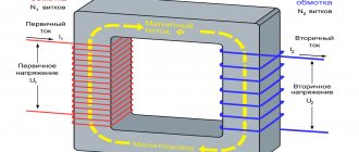
When you turn on the device by pressing the button, the input circuit of the power supply is closed, the high voltage is converted by the transformer into low voltage on the secondary winding, and a current arises in the output circuit, which quickly heats the tip. When the button is released, the circuit opens, the current stops flowing and heating stops.
The current strength in the operating circuit reaches 25-50 amperes at a low voltage of about 2 volts. The secondary winding of the transformer must be wound with wire and must have a cross-section several times larger than the cross-section of the tip wire. The same applies to the conductive busbars connecting the ends of the tip to the secondary winding. This will prevent them from overheating and wasting energy to heat them.
Instead of a transformer, switching power supplies have recently begun to be used more and more widely. They make it possible to reduce the weight and dimensions of the unit several times with the same performance.
How does it work
The main difference between an induction soldering iron and a conventional soldering iron is whether there is a heating element or no heating element at all. The tool heats up due to the presence of eddy currents under the influence of an alternating magnetic field.
An induction soldering iron has a coil into which the rod of the device is inserted.
The process of heating the inductor is as follows:
- The generator supplies 36V high frequency current to the inductor via the power line.
- The current flowing through the inductor turns into an alternating magnetic field, the line of force of which intersects the axis of the tip located inside the inductor.
- The magnetic field that interacts with the ferromagnetic spray on the tip causes its magnetization to rotate and form a vortex electric field. This process is accompanied by a large release of heat and very rapid heating of the shank, after which the entire surface is at a high temperature.
- Current regulation (the frequency of which determines the temperature of the tip) is carried out using an adjustment sensor on the electronic unit. An induction soldering station uses two methods to control the heating temperature of the soldering iron: using a temperature sensor built into the soldering iron tip and replaceable cartridges. In the first method, the thermocouple in the head of the soldering iron sends a signal to the electronic unit, and the electronic unit adjusts the temperature in accordance with the received data. For the second adjustment method, it is necessary to have additional replaceable tips.
Important! Not all models come with replacement tips. Therefore, you should take care in advance to purchase them if necessary.
Operating principle
Features of devices
Among the features of induction soldering irons, we should note a thin, replaceable cartridge, on which the heating temperature of the tip largely depends.
It is a thin tube, which, in combination with the lightweight body of the device, makes it possible to sit for a long time during the soldering process.
The hand does not get tired, which means that the accuracy of the tip and solder supply does not change, there are no leaks of excess material, and the speed of operations increases. There is no complex electronic circuit, the degree of heating is adjusted automatically.
In all respects, an induction soldering iron is more advanced than traditional soldering devices. Although it is not yet widespread enough, this design can be classified as a new generation of technology.
DIY induction soldering station
Making an induction soldering iron with your own hands is not particularly difficult or expensive. But it has several disadvantages. Firstly, the power and efficiency of this device will be low. Secondly, the device will not have a large number of additional functions and adjustments, as it might have been with the factory version. Therefore, the most acceptable option is to buy a cheap Chinese analogue.
Copper rod
If you still want to make a soldering iron yourself, then you need to follow this algorithm:
- select a suitable tube that will serve as the housing.
- install a metal tube of smaller diameter into it. An improvised reel will be wound on it.
You might be interested in this Features of the instrumentation and automation profession
Rod and body
- Make approximately 12 turns using copper wire with a diameter of about 1 mm.
Important: The turns should not touch.
- the rod and coil are covered with a layer of insulation.
- A copper rod is built into the tube, which will serve as a sting.
- Any transformer that reduces the voltage is used for power supply.
Homemade soldering iron option
Remaking an electronic transformer
The switching power supply for the soldering iron is taken “as is” and undergoes minimal modifications. Most often, a switching power supply is used for halogen lamps with a voltage of 12 volts and a power of 60 watts, but any with similar parameters will do.
Since modern power supplies use non-separable toroidal transformers wound on a ferrite ring and firmly fixed to the board, the old secondary winding is not removed, but simply turned off.
A new secondary winding is made from just one turn of a large-section copper busbar, carefully inserting it into the central hole of the output transformer.
If the wire or busbar found at hand has an insufficient cross-section, then two secondary windings should be made from one turn, connecting them to the current conductors in parallel.
In general, the process of converting an electronic transformer into a pulse soldering iron with your own hands is simpler than in the case of a low-frequency transformer.
How to use
When soldering various small radio components, according to the requirements of regulatory documents and recommendations of manufacturers of electronic components, the temperature at the tip of the working surface should not exceed 2700C. When using new device models, this parameter can be set using the adjustment knob on the electronic unit of the device. The correctness of this setting is checked by touching the tip of the device with the tip of a thermocouple connected to the multimeter. The main criteria for choosing such welding equipment are:
- power - the most convenient and practical model of a soldering station, the power of which can be adjusted from 5 to 60 W.
- frequency of the current in the inductor - for radio amateurs and semi-professionals, a current with a frequency of 400 to 700 kHz will be sufficient. Models used by professionals and workers have frequencies up to 13.5 MHz.
- Heat Control Types - Most modern devices can use smart heating technology to adjust the heating temperature of the tip.
- number of independent channels - for the ability to connect hot tweezers to a soldering iron. The device must also be equipped with 2 independent channels.
- size and weight - for ease of operation and carrying, the device should be small in size and weight (no more than 1 kg)
- When choosing, you also need to take into account the warranty period, the possibility of repair and the presence of additional components that make the soldering process more convenient.
An induction soldering iron is an effective tool for soldering. Making such a device with your own hands is not entirely advisable. It is much easier to buy a cheap Chinese analogue, which will last longer and have a large number of settings and additional functions.
Choosing the right model
The main criterion when choosing the required model can only be the scope of application of the soldering station. If you intend to use it in production or for professional purposes, then it is recommended to choose devices with “smart heating” , although they cost more than 1 thousand.
For amateurs, it is preferable to use systems with a digital keypad. They are quite enough for high-quality and convenient work. True, such options will not have a hairdryer, but you can buy it separately. This option is also convenient because there is no need to select a tip with a given Curie point each time, and this greatly simplifies the work.
Idea No. 2 – A more powerful device
To make a powerful induction boiler with your own hands, you just need to know how to use welding. In fact, the assembly technology is not too complicated and any self-taught electrician can handle it, as you will see after reading.
So, the materials you will need are:
- two pieces of metal pipe of different diameters;
- enameled copper wire;
- two adapters for heating pipes (for supply and return);
- heat-insulating casing;
- three-phase inverter.
A drawing of a homemade heater looks like this:
As you can see, one pipe needs to be welded inside the other to create a hollow tank in the form of a cylinder. Also, using a welding machine, you need to “embed” two pipes into the container for supplying cold water and discharging hot water to the heating system.
Next, as shown in the diagram above, you need to wind the copper wire around the body of the induction boiler. The winding, as you understand, will serve as a heating element and, in contact with the coolant, will heat it. It is necessary to stretch a heat-insulating cover over the created structure, then open the water supply and test the system.
We also recommend watching the visual video instructions for assembling a similar device at home:
Simple and at the same time powerful electric boiler
And finally, we advise you to familiarize yourself with the master class on making an induction boiler from tiles:
How to make homemade tiles
So we have provided 2 design options for a homemade induction boiler that heats water due to the influence of an electromagnetic field. We hope that you now know how to make a heater from improvised materials at home, because... both technologies were “chewed” from A to Z!
Related materials:
- How to make an electrode boiler with your own hands
- How to make autonomous heating of an apartment with electricity
- How to properly twist wires
Making a pulse microcircuit soldering iron
To make a soldering iron, which can be used to solder and solder microcircuits and other electronic components that are particularly sensitive to overheating into printed circuit boards, a specially modified resistor is added to the design of the device, which plays the role of a protective device. An MLT type resistor with a resistance of 8 ohms and a power dissipation of 0.5-2 watts is suitable
DIY soldering iron for microcircuits
In addition, you will need:
- A strip of double-sided foil PCB 10X30 millimeters.
- A piece of steel wire 0.8 mm thick.
- Copper wire for the tip.
- Ballpoint pen body.
- Switching power supply 12-15 volts 1 ampere.
The manufacturing sequence is as follows:
- Remove the paint coating from the resistor by heating it in a muffle furnace or gas burner.
- Use a file or jigsaw to saw off one of the terminals.
- drill a hole with a diameter of 1.1 mm in this place, reaching the internal cavity. The second pin should be connected to the power source; it will also attach the device to the handle.
- Expand the hole in the resistance housing by a cone so as to prevent contact between the tip and the internal walls of the resistor; the second wire to the power supply will need to be soldered to this place.
- The steel wire must be bent in half, a ring with the diameter of the resistor should be bent at the bend (it should fit very tightly) and bent at a right angle.
- Tin the ring, put it on the resistor and solder it so that the ends of the steel wire are directed in the same direction as the remaining lead.
- Cut the board out of a strip of PCB so that on the wide part on different sides there are two contact pads for soldering the ends of the wire and the second terminal of the resistor, respectively, the middle one should fit tightly into the handle body, and the narrow part should have contact pads for soldering wires from the power supply.
- Solder the ends of the wire and the resistance pin to the board, and solder the wires from the power supply on the arc side
- Insert a piece of heat-resistant insulator (the same ceramic, for example) tightly into the resistor hole to prevent contact of the tip with the second terminal.
- Insert the copper tip into the hole. The tip can be given any shape convenient for soldering, bent, flattened, sharpened, etc.
- Pass the wires through the handle body, insert the board into it and connect the wires to the power supply.
Soldering iron device for microcircuits
Working with such a home-made pulse microcircuit soldering iron is safe for microcircuits and does not tire your hand.
From an old Soviet resistor
A soldering iron made from a resistor is designed for 6–25 V. The presence of a range is a plus: you can use different power supplies or create a stand-alone version with a battery.
What you will need:
- Soviet wirewound resistor PEV (can be obtained in workshops, radio markets, landfills, disassemblies). An option with ceramic insulation at 20 Ohms and 7 W is suitable. Other parameters are also possible. To calculate a resistor (its main parameter is resistance, Ohm), there is the equation U²/P - the planned voltage is divided by the desired power of the soldering iron;
- textolite, plywood for holder;
- two rods made of copper: along the cavity of the resistor and thinner for the tip. They can easily be brought to the desired diameter with a file;
- a ring (bite off the spring), or a split washer (grower) is a retainer;
- a regular washer and a screw for it.
Build process
Procedure:
- At the end of the rod, a thin tap is used to make a thread (horizontally) for the screw.
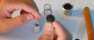
- At one end we cut out (using a file, etc.) a groove for the retainer. On the second, a cavity is drilled for the tip; there, to fix the tip in the copper casing, it is advisable to make a threaded hole (not shown in the images) for a screw (vertically) with which it will be clamped.
- The elements are collected.
- Everything is inserted into a resistor. At its rear end, such a heating unit is fixed with a bolt and washer.
- A handle is cut out of PCB: two plates with holes for the bolts holding them together. Preliminarily plan grooves or places for placing wiring inside.
- Solder the power supply wires to the resistor terminals.
- Collect the pen. The cable inside will be clamped between the plates, so the fixation is secure.
Assembly will be made easier if the role of the casing is not a solid copper rod that needs to be drilled, but a tube, where it is easier to insert the tip. Copper is a soft metal, so in the described part, if there is no tap, the thread can be made with the bolt itself.
Safety regulations
For heating systems that use induction heating, it is important to follow several rules to avoid leaks, loss of efficiency, energy consumption, and accidents
- Induction heating systems require a safety valve to release water and steam in case the pump fails.
- A pressure gauge and an RCD are required for the safe operation of a heating system assembled by yourself.
- Having the entire induction heating system grounded and electrically insulated will prevent electric shock.
- To avoid the harmful effects of the electromagnetic field on the human body, it is better to move such systems outside the residential area, where installation rules must be followed, according to which the induction heating device must be placed at a distance of 80 cm from horizontal (floor and ceiling) and 30 cm from vertical surfaces.
- Before turning on the system, be sure to check the presence of coolant.
- To prevent failures in the operation of the electrical network, it is recommended to connect a boiler with induction heating, made by hand according to the proposed schemes, to a separate supply line, the cable cross-section of which will be at least 5 mm2. Conventional wiring may not be able to handle the required power consumption.
Ultrasonic soldering
Ultrasonic soldering is a flux-free soldering technology that does not require any chemicals and uses ultrasonic energy to solder materials such as glass, ceramics, composite materials, and metals that are difficult or impossible to solder using traditional means.
This technology is increasingly used when soldering together metal and ceramic parts included in the design of solar cells, as well as parts made of medical alloys with shape memory used in specialized electronic modules and sensor units.
Ultrasonic soldering has been mentioned since 1955 as a method for soldering aluminum and other metals without the use of flux.
This technology differs significantly from ultrasonic welding. The latter uses ultrasonic energy to join parts without adding any fillers, while traditional (and ultrasonic) soldering uses external heat to form the joint to melt metal fillers, i.e. solders. In this case, ultrasonic soldering can be performed using either a special soldering iron or a special soldering bath.
This process can be carried out either automatically during mass production or manually during prototyping or repair work.
Ultrasonic soldering was originally intended for joining aluminum and other metals, but today, with the advent of active solders, a wider range of metals, ceramics and glass can be soldered.
This technology uses either ultrasonic soldering irons with a tip with a diameter of 0.5-10 mm, or ultrasonic soldering baths. These devices use piezoelectric crystals to generate high-frequency (20-60 kHz) sound waves in layers of molten solder or in a bath of molten solder to mechanically destroy oxide films formed on the surfaces of the melt. In this case, the tips of ultrasonic soldering irons are simultaneously connected to the heating element, while the piezoelectric crystal is thermally insulated to prevent its destruction.
The tips of ultrasonic soldering irons can heat up to 450 °C during mechanical vibrations with a frequency of 20-60 kHz. Such a tip is capable of melting metal fillers of solder by exciting sound vibrations in the molten solder. At the same time, vibration and cavitation (pore formation) in the resulting melt allow solders to wet the surfaces of many metals and adhere to them.
The energy of sound waves generated by the tip of an ultrasonic soldering iron or an ultrasonic solder bath causes cavitation in the molten solder, which mechanically destroys the oxide films located on top of the layers of the solder itself and on the metal surfaces being joined.
Cavitation in a bath of molten solder can very effectively destroy oxide films on the surfaces of many metals, but it is ineffective when soldering to ceramics and glass, since the latter are themselves oxides, as well as to other non-metallic composite materials that cannot be destroyed, since they are base substance. In case of soldering directly to glass and ceramics, metal fillers for ultrasonic soldering must be doped with active elements such as indium (In), titanium (Ti), hafnium (Hf), zirconium (Zr), and rare earth elements (cerium/Ce, lanthanum/La and lutetium/Lu). Solders doped with these chemical elements are called "active solders" because they directly act on glass or ceramic surfaces to create adhesion to them.
Ultrasonic soldering technology is increasingly used due to its cleanliness, lack of flux and compatibility with active solders, and is intended for joining parts that do not allow the use of aggressive flux or consist of dissimilar materials (metals, ceramics or glass).
For effective adhesion to surfaces, the active solder's own oxide film, formed during its melting, must be destroyed, and ultrasonic vibration is well suited for this purpose.
