Every electronic device that is connected to the network needs protection from exceeding threshold current or voltage values. Various fuses and circuit breakers are used for current protection, but varistors are most often used to protect the device from overvoltage. In this article we will look at the operating principle of a varistor, its characteristics, advantages and disadvantages of this electronic component.
What is a varistor
A varistor is a variable resistor made of semiconductor material that is capable of changing its electrical resistance depending on the voltage applied to it.
The operating principle of such an electronic component differs from a conventional resistor and potentiometer. A standard resistor has a constant resistance value at any time, regardless of the voltage in the circuit; a potentiometer allows you to change the resistance manually by turning the control knob. But the varistor has a nonlinear symmetrical current-voltage characteristic and its resistance completely depends on the voltage in the circuit.
Thanks to this property, varistors are widely and effectively used to protect electrical networks, machines and equipment, as well as radio-electronic components, boards and microcircuits, regardless of the type of voltage. They have a low manufacturing price, are reliable in use and can withstand high loads.
Varistors are used both in high-voltage installations up to 20 kV, and in low-voltage installations from 3 to 200 V as a voltage limiter. Moreover, they can operate both in networks with alternating and direct current. They are used to regulate and stabilize current and voltage, as well as in overvoltage protective devices. They are used in the design of surge protectors, power supplies, mobile phones, SPDs and other SPS.
AC transient waveform
Varistors are connected directly to the power supply circuits (phase-neutral, phase-phase) when operating on alternating current, or plus and minus power when operating on direct current and must be designed for the appropriate voltage. Varistors can also be used to stabilize DC voltage and mainly to protect the electronic circuit from high voltage surges.
Varistor properties
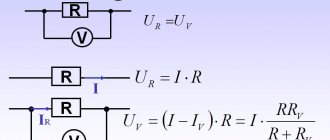
The main property of a varistor is its ability to reduce its own resistance depending on the voltage supplied to it. The higher the voltage is applied, the less resistance it begins to have. Varistors are connected to the electrical board in parallel with the protected device; in normal mode, the varistor operates at the rated voltage of the device it protects.
In normal mode, the electricity passing through the varistor is negligible, and therefore in such conditions it acts as an insulator.
If a sharp surge in electricity occurs, the varistor, due to its nonlinear characteristics, instantly reduces the value of its resistance to tenths of an ohm and removes the load from the general network, protecting it by radiating the excess energy received with heat. In such situations, a voltage of thousands of amperes can instantly pass through the varistor.
A varistor is a completely inertia-free device; as soon as the voltage in the network increases, its resistance immediately drops.
Characteristics
A varistor is a semiconductor resistor with a nonlinear current-voltage characteristic; its graph is shown in Figure 2.
Rice. 2. Typical current-voltage characteristics: A – varistor, B – conventional resistor
As can be seen from the graph, when the voltage across the semiconductor reaches a threshold value, the current increases sharply, which is caused by a decrease in resistance. This characteristic allows the varistor to be used as protection against short-term voltage surges.
Types of varistors
In appearance there are:
- film;
- in the form of tablets;
- core;
- disk.
Rod ones can be equipped with a moving contact. They will look like their name. In addition, there are low voltage, 3-200 V and high voltage 20 kV. For the former, the current fluctuates between 0.0001-1 A. This does not affect the designation according to the diagram in any way. In radio equipment, of course, low voltage is used.
To check the performance of the varistor, you need to pay attention to the appearance. It can be found at the input of the circuit (where power is supplied). Since a very large current passes through it - compared to the protected circuit - this, as a rule, affects its body (chips, burnt areas, darkening of the varnish coating). And also on the board itself: at the soldering site, the wiring tracks may peel off, causing the board to darken. In this case, it must be replaced.
However, even if there are no visible signs, the varistor may be faulty. To check its serviceability we will have to unsolder one of its pins, otherwise we will check the circuit itself. For continuity testing, a multimeter is usually used (although you can, of course, try a megger, you just need to take into account the voltage it creates so as not to burn the varistor). It is not difficult to ring it; it is connected to the contacts and its resistance is measured. We set the tester to the highest possible limit and make sure that the value is at least several hundred megohms, provided that the multimeter voltage does not exceed the response voltage of the varistor.
However, an infinitely large resistance, provided that the ohmmeter is quite powerful (if I can use this word), this also indicates a malfunction. When checking a semiconductor, it is necessary to remember that it is still a conductor and it must show resistance, otherwise we have a completely burnt part.
Operating principle of varistors
In its normal state, a varistor has a very high resistance (according to various sources, from hundreds of millions of Ohms to billions of Ohms). It passes almost no current through itself. As soon as the voltage exceeds the permissible value, the device loses its resistance thousands, or even millions, of times. After the voltage normalizes, its resistance is restored. If a varistor is connected in parallel with an electrical appliance, then during a voltage surge the entire load will fall on it, and the devices will remain safe.
The principle of operation of a varistor, if explained in simple terms, boils down to the following. When there is a surge in the electrical network, it acts as a valve, passing through itself an electric current in such a volume as to reduce the potential to the required level. After the voltage has stabilized, this “valve” closes and our electrical circuit continues to operate as normal. This is the purpose of a varistor.
Marking, main characteristics and parameters
Each varistor manufacturer labels its product in a certain way, so there are quite a large number of designation options and their interpretations. The most common Russian varistor is K275, and popular foreign-made components are 7n471k, kl472m and others.
Recommended reading: Stepper motor control
The designation of the CNR-10d751k varistor can be deciphered as follows: CNR – metal oxide varistor; d – means that the component is disk-shaped; 10 is the diameter of the disk; 751 – response voltage for this device (calculation is done by multiplying the first two digits by 10 to the power equal to the third digit, that is, 75 multiplied by 10 to the first power, you get 750 V); k is the permissible deviation of the rated voltage, which is equal to 10% in any direction (l – 15%, M – 20%, P – 25%).
The main characteristics of varistors are the following parameters:
Classification voltage is the voltage at certain values of current flowing through the varistor (usually this value is 1 mA). This parameter is conditional and does not affect the device selection;
The maximum permissible voltage is the voltage range (rms or rms value) at which the varistor begins to reduce its resistance;
Maximum absorption energy is a characteristic showing the value of energy that the varistor dissipates and does not fail when exposed to a single pulse (measured in Joules);
Maximum pulse current – normalizes the rise time and duration of the current pulse (measured in Amperes);
Capacitance is a very important parameter, which is measured when the varistor is closed and at a given frequency (drops to zero if a large current is applied to the varistor);
Permissible deviation - deviation from the nominal potential difference in both directions (indicated as a percentage).
Response time is the period of time during which the varistor transitions from a closed state to an open state (usually several tens of nanoseconds).
Marking features
There are many designation options that manufacturers use. The marking is mainly influenced by the technical characteristics of an individual varistor. Such indicators usually include the required current level or permissible voltage.
The difference in parameters also determines the labeling options. The most popular abbreviations include the designation CNR with the addition of the character set 07D390K.
Let's look at how each of the available symbols is deciphered. CNR is a type of device itself. In our case we are talking about a metal oxide varistor.
Advantages and disadvantages of varistors
Important advantages of a nonlinear resistor (varistor) are its stable and reliable operation with high frequencies and heavy loads. It is used in many devices operating with voltages from 3 V to 20 kV, is relatively simple and cheap to produce and is effective in operation. Additional important benefits are:
- high response speed (nanoseconds);
- long service life;
- ability to monitor voltage drops (inertia-free method).
Despite the fact that this electronic component has many advantages, it also has disadvantages that affect its use in various systems. These include:
- low-frequency noise during operation;
- component aging (loss of parameters over time);
- high capacity: depends on the voltage and type of element, ranges from 70 to 3200 pF and affects the performance of the device;
- at maximum voltage values, power is not dissipated - it overheats significantly and fails at prolonged maximum voltage values.
Diagnostics
To test this electronic device, special equipment called a tester is used. So, to carry out the test you will need a varistor, the principle of which is to change the resistance parameters, and a testing device. Before you start, you need to turn on the device and switch to resistance mode. Only then will the device meet all the necessary technical requirements, and the amount of resistance will be enormous.
Before starting testing, it is necessary to check the technical condition of the device. First of all, you should look at its appearance. The device should not show any cracks or signs that it has burned out. You should not inspect the device negligently, as any minor breakdown can lead to unpleasant circumstances.
Varistor selection
To choose the right varistor for a particular device, you need to know the characteristics of its power source: resistance and transient pulse power. The maximum permissible current value is determined, among other things, by the duration of its influence and the number of repetitions, therefore, if you install a varistor with a low peak current value, it will quickly fail. In short, to effectively protect the device it is necessary to choose a varistor with a voltage that has a small margin to the rated one.
Also, for the trouble-free operation of such an electronic component, the rate of dissipation of absorbed thermal energy and the ability to quickly return to a state of normal operation are very important.
How to check a varistor with a multimeter?
Checking a varistor using a tester or multimeter is a useful skill for radio amateurs and people who are handy and like to repair broken equipment themselves. This will be discussed in this article. What a varistor is intended for and what it does is described in sufficient detail in this article - an article about a varistor.
But let’s remember a little: a varistor is designed to protect variable or permanent circuits from overvoltage. It stands parallel to the circuit being protected and normally has a high resistance.
When the threshold voltage is reached, which depends on the brand of the varistor, its resistance decreases from very high to very small. A varistor absorbs this overvoltage and dissipates it into the atmosphere as heat.
Thus, it removes excess energy from the circuit, thereby protecting the circuit from failure.
Now let's start checking. Before using the tester, carefully inspect the radio element. It may have signs of burning, chips, or even break down.
We recommend reading: How to measure resistance with a multimeter: instructions, photos, videos
A careful inspection will save you from unnecessary work, although checking with a device does not take much effort, but still.
A varistor can also lose its properties over time, from external conditions and during the aging process - this is also worth paying attention to.
Measurements with a dial gauge
Such a device is considered analog. Its design uses an electromechanical head. It is a frame placed in a magnetic field. Depending on the current strength, the arrow in the frame deviates, stopping in a certain position. The range of needle deflection is graduated by numbers, according to which the resistance is calculated.
Before you start checking the varistor, you will need to set up the dial multimeter. To do this, it is calibrated. Its essence comes down to setting the zero position of the arrow by rotating a special handle while connecting the probes to each other.
To do this, the switch button selects the operating mode corresponding to the “Ω” icon, and the slide switch is set to the highest limit of resistance measurement by the tester. Most often it is designated as “x100”, which corresponds to megaohms. The resistance is measured from the power source (battery) installed in the device. Therefore, if you cannot set the needle to zero, the battery will need to be replaced.
When carrying out direct measurements, touch one terminal of the varistor with one probe of the tester, and touch the other with the other. As a result, three outcomes are possible:
- The arrow will deflect to zero or show resistance in the kilo-ohm region. A conclusion is made that the element is faulty (breakdown).
- The measurement result is within hundreds of megaohms. This reading indicates the serviceability of the varistor.
- When you touch the terminals of the radio element, the arrow does not react in any way. Possible reasons are as follows: the operating range of the device is not enough to measure the resistance value of the varistor, the device is faulty, the radio element is faulty (break).
Digital tester
Using a digital multimeter, checking the varistor for functionality will be a little easier than using an analog one. This is due to the fact that the digital tester has an LCD display in its design, which clearly displays the measured resistance.
The operation of this type of tester is based on an analog-to-digital converter, the operating principle of which is based on comparing the measured signal with a reference one. It should be noted that if, when you turn on the tester, a flashing battery icon appears on the screen, the battery will need to be replaced. The procedure for measuring the resistance of a varistor can be represented as follows:
The switch sets the maximum resistance measurement limit. Typically this limit is indicated by a number and a letter. If just numbers are written, then the unit of measurement is Ohm, the letter K after the number means kilo-ohm, the letter M means mega-ohm.
- The probes are fixed on two terminals of the varistor, and the reverse ends of the wires with plugs are inserted into the tester sockets marked Ω and COM. Since the polarity of the signal applied to the varistor does not matter, it does not matter which wire is connected to which terminal of the element. Although it is customary that a black cord is inserted into the COM connector.
- The device is turned on by pressing the ON/OFF button on the tester.
- If a unit is displayed on the indicator, this means that a small measurement limit has been selected.
- If numbers other than one are displayed on the screen, then this is the value of the measured resistance.
When interpreting the measurement result, the tolerance should also be taken into account. Each radio element has its own tolerance indicator. For example, if the tolerance is 10 percent and the internal resistance of the varistor is specified as 100 MΩ, then the results obtained should be between 90 and 110 MΩ. If the measured resistance of an element is found to be below or above this range, then it can be considered faulty.
How to find a varistor on the board?
According to the diagram above, it is clear that this element is located next to the fuse at the point where the power wires enter the board. This is usually a yellow or dark green disc.
In the photo the varistor is indicated by a red arrow. One might think that the varistor is a blue part covered with black soot, but on magnification one can see cracks on the varistor body, from which nearby parts are covered with soot. This is clearly visible on the reverse side, where the symbols are written. Even if they are not there, you can recognize a varistor, knowing that it is connected in parallel to the load or by the markings on its body.
VA1 is a varistor, and the blue part next to it is capacitor C70.
Do not confuse them, they are the same in shape, so be guided by the markings and symbols on the board.
After you have found a varistor, you need to unsolder it so that you can then install a new one in its place. To solder varistors, I usually use a gas soldering iron, because there is not always power supply at the repair site - at a facility under construction, on the roof, for example. It is also very convenient to use a desoldering pump - heat up the soldering area and remove the melted solder with a desoldering pump.
But for these purposes, tweezers or ordinary pliers are quite suitable - you need to grab the leg of the part and pull it out when the solder melts. If your solder does not melt well, then most likely it is high-temperature on the board - the so-called lead-free (you may have noticed the inscription PbF on my board - plumbum free). In this case, you need to either increase the temperature of the soldering iron tip or drop another lower temperature one on top, the soldering area will melt and the part can be removed. After this, we insert a new varistor and solder it.
We recommend reading: Thyristors: principle of operation, testing and characteristics
For soldering, it is very convenient to use solder in the form of a wire that already has flux inside.
Also note that most boards are double-sided, so you need to solder the legs of the part on both sides of the board, since it often happens that the leg of the part acts as a jumper between tracks on different sides of the board.
After replacing the varistor, all that remains is to install a new fuse and install the board in place.
Typically, air conditioner circuit boards contain varistors for a voltage of 470 V, and fuses rated from 0.5 A to 5 A. Therefore, I recommend that you always have a small supply of these parts with you.
For those who need to repair the board by replacing the varistor, our service specialists will help, see prices here.
Designation on the diagram and options for connecting a varistor
On diagrams, a varistor is usually designated as a regular resistor, but with the addition of the letter U next to the slash. This feature indicates in the diagrams that this element has a dependence of resistance on voltage in the circuit. Also on the electrical diagram, this element is marked with two letters R and U with the addition of a serial number (RU1, RU2 ... etc.).
There are a large number of options for connecting varistors, but what is common to all methods is that this component is connected in parallel to the power circuit. Therefore, in the absence of dangerous values of voltage pulses, the current that flows through the varistor is small (due to large resistance values) and does not in any way affect the performance of the system. When an overvoltage occurs, the varistor changes the resistance to small values, the load is shunted, and the absorbed energy is dissipated into the surrounding space.
General information
A varistor is a semiconductor resistor that decreases its resistance as the voltage increases. The conventional graphic symbol (UGO) is presented in Figure 1, which shows the dependence of the resistance of the radio component on the voltage value. In the diagrams it is denoted znr. If there is more than one, then it is designated in the following form: znr1, znr2, etc.
Figure 1 - UGO varistor.
Many beginning radio amateurs confuse a variable resistor and a varistor. The operating principle, main characteristics and parameters of this element differ from a variable resistor. In addition, a common mistake in drawing up electrical circuit diagrams is the incorrect UGO. A varistor looks like a capacitor and is recognized only by its markings.
Use in everyday life
The characteristics of the element allow it to be used in devices associated with communication channels, various inputs for equipment, and the use of varistors for generators.
They are installed in surge protectors of special extension cords, as well as in other high-quality input models for protection. It is recommended to install the element in Chinese equipment to avoid quick breakdowns. To ensure the safety of the entire room, the varistor must be installed on a DIN rail.
Device
Varistors are designed quite simply - inside there is a crystal of semiconductor material, most often it is Zinc Oxide (ZiO) or Silicon Carbide (SiC). The pressed powder of these materials is subjected to high-temperature treatment (baked) and covered with a dielectric shell. They are either available in versions with axial leads, for mounting into holes on a printed circuit board, or in an SMD package.
The figure below clearly shows the internal structure of a varistor:
Varistors are "formed" when crystals of silicon carbide or metal oxides are pressed into a ceramic material.
Example of protection implementation
Figure 4 shows a fragment of a computer power supply circuit diagram, which clearly shows a typical varistor connection (highlighted in red).
Figure 4. Varistor in the ATX power supply
Judging by the figure, the circuit uses the TVR 10471K element, we use it as an example of decoding the markings:
- the first three letters indicate the type, in our case this is the TVR series;
- the next two digits indicate the diameter of the case in millimeters, respectively, our part has a diameter of 10 mm;
- Then there are three numbers that indicate the effective voltage for this element. It is deciphered as follows: XXY = XX*10y, in our case it is 47*101, that is, 470 volts;
- the last letter indicates the accuracy class, “K” corresponds to 10%.
You can also find simpler markings, for example, K275, in this case K is the accuracy class (10%), the next three digits indicate the magnitude of the effective voltage, that is, 275 volts.
Marking
We have already paid enough attention to studying what a varistor is. The marking of this device is complex, and therefore, when purchasing a device, it cannot be judged by the data located on the case. Let's look at this example: there is a CNR-06D400K. CNR is the name of the type, in this case we have a metal oxide varistor. 06 - it has a diameter of 6 millimeters. D – we have a disk varistor. 400 – response voltage. K - this letter indicates that the tolerance for possible deviation has an error of 10%. If we talk about computer technology, then their varistors are designed for 470V. Agree, a lot. But there is more than one varistor! The marking of these parts is carried out by each major manufacturer in its own way, so there are no universal and standardized recognition rules. Therefore, you need to use either the help of sellers or resort to the services of reference books.
Varistor manufacturing
All this is explained by the device of the varistor. A varistor consists of a semiconductor and various bonding materials. A common combination is silicon carbide and epoxy resin. They are fused at high temperatures. Then, the surface of the varistor is coated with metal and the outputs are soldered.
Varistor design
The ability of a varistor to conduct high voltage through itself is provided by the material – silicon. When heated, silicon carbide crystals significantly reduce their resistance. And current can easily pass through them.
However, zinc oxide varistors are becoming increasingly common. They are easier to manufacture and can pass higher voltage pulses through them. The technique for their production is similar to the production of ceramic varistors.
Varistors come in various forms - cones, rods, disks. It all depends on the manufacturer.
Different forms of varistors
Capacitance values
Because the main conducting region of a varistor between its two terminals behaves like a dielectric, below its clamping voltage the varistor acts like a capacitor rather than a resistor. Each semiconductor varistor has a capacitance value that is directly proportional to its area and inversely proportional to its thickness.
When used in DC circuits, the capacitance of a varistor remains more or less constant provided that the applied voltage does not increase above the clamp voltage level and drops sharply near its maximum DC voltage rating.
Read also: Do-it-yourself press from a jack, drawings, dimensions
However, in AC circuits, this capacitance can affect the resistance of the device body in the non-conductive leakage region of its IV characteristics. Since they are usually connected in parallel with an electrical device for surge protection, the leakage resistance of varistors drops rapidly with increasing frequency.
This relationship is approximately linear with frequency, and the resulting parallel resistance, its AC reactance Xc , can be calculated using the usual 1/(2πƒC) , as for a normal capacitor. Then, as the frequency increases, the leakage current also increases.
But along with silicon semiconductor varistors, metal oxide varistors have been developed to overcome some of the limitations associated with their silicon carbide cousins.