5 common questions asked by beginning radio mechanics; 5 best transistors for regulators, circuit composition test
An electrical voltage regulator is needed so that the voltage can be stabilized. It ensures reliable operation and longevity of the device.
The regulator consists of several mechanisms.
TEST:
The answers to these questions will allow you to find out the composition of the 12 volt voltage regulator circuit and its assembly.
- What resistance should the variable resistor have?
a) 10 kOhm
b) 500 kOhm
- How should the wires be connected?
a) Terminals 1 and 2 – power, 3 and 4 – load
b) Terminals 1 and 3 – load, 2 and 4 – power
- Do I need to install a radiator?
a) Yes
b) No
- The transistor must be
a) KT 815
b) Any
Answers:
Option 1. The resistor resistance is 10 kOhm - this is the standard for installing the regulator, the wires in the circuit are connected according to the principle: 1 and 2 terminals for power, 3 and 4 for load - the current will be distributed correctly to the required poles, a radiator must be installed - to protect against overheating, The transistor used is KT 815 - this will always do. In this embodiment, the constructed circuit will work, the regulator will begin to work.
Option 2. Resistance 500 kOhm - too high, the smoothness of the sound in operation will be disrupted, or it may not work at all, terminals 1 and 3 are the load, 2 and 4 are power, a radiator is needed, in the circuit where there was a minus there will be a plus, any transistor - You can really use whatever you want. The regulator will not work because the circuit is assembled incorrectly.
Option 3. Resistance 10 kOhm, wires - 1 and 2 for load, 3 and 4 for power, resistor has a resistance of 2 kOhm, transistor KT 815. The device will not be able to work, since it will overheat greatly without a radiator.
Generator voltage regulator
The generator converts electricity.
Without a generator, the entire on-board system of the car would not work. A special sensor is connected to the magnet winding. Simple springs are the driving device. A small lever is used for the comparison device. The group of contacts plays the role of an actuator. A constant resistance is an adjustment element that is often used in machines. During operation of the generator, a current arises at its output. The resulting current passes into the winding of the magnetic relay. As a result, a magnetic field appears and, under its influence, the lever arm moves apart. A spring begins to act on it and plays the role of a comparing device. When the current exceeds the required values, the contacts on the magnetic relay move apart. At this time, the constant resistance in the circuit is turned off. Less current flows into the winding.
Perhaps it is useful for everyone to know what the accuracy class of an electric meter is.
Adjustment features
It makes sense to talk about this or that 12 volt regulator only if you provide additional data:
- DC or AC voltage must be regulated;
- what is the maximum current in the load;
- the magnitude of the potential difference in front of the regulator;
- load voltage parameters in the regulation range.
Each of the listed parameters is associated with certain technical solutions that are reflected in the diagram. The general circuit of the regulator is a load that is connected to some device. It is conventionally indicated by a rectangle in the diagram shown below. Inside this rectangle there may be one or another diagram that corresponds to the additional data mentioned above. The simplest regulator is a variable resistor. It allows you to regulate AC voltage without distortion. This resistor is also applicable for direct current.
Circuit with variable resistor.
Elementary circuit of a regulator Circuit with a variable resistor
If the potential difference at the input is significantly greater than 12 volts at the output, energy will be lost in the regulator. The variable resistor will generate heat. To avoid heat loss, it is necessary to use variable inductance on alternating current, which can be LATR. Its throughput is limited, as in a variable resistor, by the design of the moving contact. But if switching is permissible by placing jumpers with reliable contacts between the turns, a significant current can be obtained.
Inductive regulator
Another way to regulate 12 volt alternating voltage with your own hands is to change the inductance of the regulator. To do this, manually change either the gap or the number of turns specifically designed for this. An adjustable welding transformer used to power a voltaic arc is designed according to this principle. If the 12 volt voltage regulator does not have the properties of a stabilizer and is controlled by yourself, the potential difference across the load must be monitored with a voltmeter.
A variable resistor and variable inductance can also be used as a current regulator. In this case, it is necessary to monitor the current in the load with an ammeter. If the voltage parameters at the load are not specified, with the exception of its value of 12 V, you can regulate it with a dimmer. This can be a powerful regulator since it is usually thyristor based. And modern thyristors are produced for a very wide range of potential difference and current.
DIY thyristor charger
There are many electronic circuits, including complex ones, with a full range of adjustments and protection, a significant number of parts, often not cheap. But most car enthusiasts prefer simple thyristor chargers, made from several inexpensive components, which can often be extracted from used equipment, such as a computer.
Selection of the scheme and principle of its operation
First, it is worth noting the main advantage of the proposed thyristor charger circuit: availability and low financial costs. There are other advantages when using the inexpensive thyristor KU202 as the main component:
- Good charging current up to 10 A.
- The energy output is pulse type, which extends the service life of the charged battery.
- For assembly you will need widely available inexpensive parts that are not difficult to find.
- The circuit of a thyristor charger for a car battery can be easily repeated even by a car enthusiast with little knowledge of radio engineering, and an experienced electronics engineer will need no more than an hour to put the device into operation.
According to the principle of operation, this is a phase-pulse power regulator made on a thyristor and allows you to change the current strength. The control electrode KU202 is powered by a transistor circuit. To protect the thyristor charger circuit for a car battery from current surges, a diode VD2 is used. Resistance R5 affects the charging current, the value of which, as is known, is 1/1 of the battery capacity. To power the circuit, you will need a transformer that reduces the mains U = 220 V to 18–22 V. If you have a transformer with a high output voltage at your disposal, the resistance R7 needs to be increased to approximately 2 kOhm (you may have to select a resistor). The rectifier bridge diodes and thyristor must be installed on aluminum radiators to prevent overheating of the parts. When installing conventional elements of type D242–245, do not forget to place an insulating washer under the body.
The schematic diagram of a thyristor charger for a car battery is as follows:
Since the circuit is simple, it does not have electronic protection: its role is played by a fuse installed at the output. When charging batteries with a capacity of no more than 60 A*h, a fuse-link with a rating of 6.3 A is sufficient. Installing a series-connected device - an ammeter - will help control the charging procedure. Below is a printed circuit board that simplifies the assembly of the charger:
List of components in the circuit and selection of possible analogues
The circuit uses an electrolytic capacitor that can withstand a voltage of at least 63 V. The power of resistors R1-R6 is 0.25 W, R7 is 2 W. The diodes in the rectifier bridge pass a current of up to 10 A and maintain a reverse U of 50 V. The pulse diode VD2 must withstand the same voltage. Transistors VT1 and VT2: KT3107, KT502, KT361 and KT503, KT315, KT3102, respectively.
Calculation of transformer, thyristor and diode parameters
One of the negative aspects of thyristor charging is low efficiency, partly due to the secondary winding of the transformer, which must freely pass a current three times greater than the power consumed by the battery. How to fix it? To do this, you can move the thyristor from winding II of the transformer to winding I, as shown in the diagram of a thyristor battery charger:
The whole difference of this thyristor charger for car batteries lies in the connection of the diode bridge and the regulating thyristor to the primary winding of the transformer. Since winding current II is approximately 10 times less than the charging current, very little thermal energy is released on the diodes and thyristor: you don’t even need to use cooling radiators (but this does not apply to VD5-VD8).
Components and their analogues:
- rectifier unit KTs402.405 with any index (A, B, C);
- Zener diode type KS524, KS518, KS522;
- transistor KT117 with letters from “B” to “G”;
- the diode bridge located at the output must consist of components rated at 10 A (D242-247).
Regulation with stabilization
To obtain the specified voltage or load current parameters, stabilizers are used. In them, the output voltage or current is compared with a reference value, and at a minimum specified change, the regulator is automatically compensated by the control of the corresponding semiconductor device. There are a huge number of different schemes for various stabilizers. The easiest to use are integrated circuits.
- Linear voltage stabilizer with adjustment on TL431 and NPN transistors
Appearance and connection diagram of the 12 V stabilizer microcircuit
Such ready-made stabilizers are very convenient for powering LEDs both in cars and in lighting systems. When powered from a 220 volt network, a step-down transformer with a rectifier is required, connected to the input. Since in many cases the load parameters are very specific, special voltage and current stabilizers are made. They can operate in both continuous and pulse modes. But that's a completely different story...
5 common questions asked by beginning radio mechanics; 5 best transistors for regulators, circuit composition test
An electrical voltage regulator is needed so that the voltage can be stabilized. It ensures reliable operation and longevity of the device.
The regulator consists of several mechanisms.
TEST:
The answers to these questions will allow you to find out the composition of the 12 volt voltage regulator circuit and its assembly.
- What resistance should the variable resistor have?
a) 10 kOhm
DIY adjustable power supply
A power supply is a necessary thing for every radio amateur, because to power electronic homemade products you need a regulated power source with a stabilized output voltage from 1.2 to 30 volts and a current of up to 10A, as well as built-in short circuit protection. The circuit shown in this figure is built from the minimum number of available and inexpensive parts.
Scheme of an regulated power supply on an LM317 stabilizer with short-circuit protection
The LM317 IC is an adjustable voltage regulator with built-in short circuit protection. The LM317 voltage stabilizer is designed for a current of no more than 1.5A, so a powerful MJE13009 transistor is added to the circuit, capable of passing through itself a really high current of up to 10A, according to the datasheet, a maximum of 12A. When you rotate the knob of the variable resistor P1 by 5K, the voltage at the output of the power supply changes.
There are also two shunt resistors R1 and R2 with a resistance of 200 Ohms, through which the microcircuit determines the output voltage and compares it with the input voltage. 10K resistor R3 discharges capacitor C1 after the power supply is turned off. The circuit is powered by voltage from 12 to 35 volts. The current strength will depend on the power of the transformer or switching power supply.
I drew this diagram at the request of novice radio amateurs who assemble circuits using wall-mounted installations.
Scheme of an regulated power supply with short-circuit protection on LM317
It is advisable to carry out the assembly on a printed circuit board, so it will be beautiful and neat.
Printed circuit board of the regulated power supply on the LM317 voltage regulator
The printed circuit board is made for imported transistors, so if you need to install a Soviet one, the transistor will have to be unfolded and connected with wires. The MJE13009 transistor can be replaced with the MJE13007 from the Soviet KT805, KT808, KT819 and other npn structure transistors, it all depends on the current you need. It is advisable to reinforce the power paths of the printed circuit board with solder or thin copper wire. The LM317 voltage stabilizer and the transistor must be installed on a radiator with sufficient area for cooling; a good option is, of course, a radiator from a computer processor.
It is advisable to screw a diode bridge there. Don't forget to insulate the LM317 from the heatsink with a plastic washer and a heat conductive gasket, otherwise there will be a big boom. Almost any diode bridge can be installed with a current of at least 10A. Personally, I installed the GBJ2510 at 25A with double the power reserve, it will be twice as cool and reliable.
And now the most interesting part... Testing the power supply for strength.
I connected the voltage regulator to a power source with a voltage of 32 volts and an output current of 10A. Without load, the voltage drop at the output of the regulator is only 3V. Then I connected two series-connected halogen lamps H4 55 W 12V, the lamp filaments were connected together to create a maximum load, the result was 220 W. The voltage dropped by 7V, the nominal voltage of the power supply was 32V. The current consumed by four halogen lamp filaments was 9A.
The radiator began to heat up quickly, after 5 minutes the temperature rose to 65C°. Therefore, when removing heavy loads, I recommend installing a fan. You can connect it according to this diagram. You can not install the diode bridge and capacitor, but connect the L7812CV voltage stabilizer directly to capacitor C1 of the regulated power supply.
Connection diagram of the fan to the power supply
What happens to the power supply if there is a short circuit?
In the event of a short circuit, the voltage at the output of the regulator is reduced to 1 volt, and the current is equal to the current of the power source, in my case 10A. In this state, with good cooling, the unit can remain for a long time; after the short circuit is eliminated, the voltage is automatically restored to the limit set by the variable resistor P1. During the 10-minute short-circuit test, no parts of the power supply were damaged.
Radio components for assembling an adjustable power supply on LM317
- Voltage stabilizer LM317
- Diode bridge GBJ2501, 2502, 2504, 2506, 2508, 2510 and other similar ones designed for a current of at least 10A
- Capacitor C1 4700mf 50V
- Resistors R1, R2 200 Ohm, R3 10K all resistors with a power of 0.25 W
- Variable resistor P1 5K
- Transistor MJE13007, MJE13009, KT805, KT808, KT819 and other npn structures
Friends, I wish you good luck and good mood! See you in new articles!
I recommend watching a video on how to make an adjustable power supply with your own hands
How to connect 5 parts of a 12 volt regulator.
Variable resistor 10 kOhm.
This is a 10kohm variable resistor. Changes the current or voltage in an electrical circuit, increases resistance. This is what regulates the voltage.
Radiator. Needed to cool devices in case they overheat.
Resistor for 1 com. Reduces the load on the main resistor.
How to make a diagnosis without removal?
It is not recommended to carry out such a check, since there is no way to assess the condition of the brush assembly. But cases are different, so even such a diagnosis can bear fruit. To work, you will need a multimeter or, if you don’t have one, an incandescent lamp. The main thing for you is to measure the voltage in the vehicle’s on-board network and determine if there are any surges. But they can also be noticed when driving. For example, the light flashes when the engine crankshaft speed changes.
But measurements taken using a multimeter or voltmeter with a stretched scale will be more accurate. Start the engine and turn on the low beams. Connect a multimeter to the battery terminals. The voltage should not exceed 14.8 Volts. But it is also impossible for it to fall below 12. If it is not in the permitted range, then the voltage regulator is broken. It is possible that the contacts at the connection points between the device and the generator are broken, or the wire contacts are oxidized.
Scheme number 1
There was a stabilized switching power supply that gave an output voltage of 17 volts and a current of 500 milliamps. A periodic change in voltage was required in the range of 11 - 13 volts. And the well-known voltage regulator circuit on one transistor coped with this perfectly. I added only an indication LED and a limiting resistor to it. By the way, the LED here is not only a “firefly” signaling the presence of output voltage. With the correct value of the limiting resistor, even a small change in the output voltage is reflected in the brightness of the LED, which provides additional information about its increase or decrease. The output voltage could be changed from 1.3 to 16 volts.
KT829, a powerful low-frequency silicon compound transistor, was installed on a powerful metal radiator and it seemed that, if necessary, it could easily withstand a heavy load, but a short circuit occurred in the consumer circuit and it burned out. The transistor has a high gain and is used in low-frequency amplifiers - you can really see its place there and not in voltage regulators.
On the left are removed electronic components, on the right are prepared for replacement. The difference in quantity is two items, but in terms of the quality of the circuits, the former and the one that was decided to be collected, it is incomparable. This begs the question: “Is it worth assembling a scheme with limited capabilities when there is a more advanced option “for the same money”, in the literal and figurative sense of this saying?”
DIY power supply with current and voltage regulation
Enough words, let's get down to business!
This figure shows a power supply circuit with voltage and current regulation from 2.4V to 28V and current up to 30A.
Power supply circuit with current and voltage adjustment from 2.4V to 28V 30A
An important element of this circuit is the adjustable voltage stabilizer microcircuit TL431 or, as it is also called, a controlled zener diode, which allows you to smoothly regulate the voltage from 2.4 volts to 28 volts. Thanks to four power transistors mounted on large radiators, the power supply can withstand current up to 30A. There is also current regulation and reverse polarity protection, so the power supply can and should even be used as a charger for a car battery.
A voltage divider built on a powerful 5 W resistor R1 and a variable resistor P1 limits the current at the cathode and at the control electrode of the zener diode TL431. By rotating the knob of the variable resistor P1, the output voltage of the zener diode is set; the voltage stabilizer TL431 automatically stabilizes the voltage set by the variable resistor P1. From the TL431 chip, current flows to the base of transistor T1. The transistor acts as a switch and controls two powerful bipolar transistors T2 and T3 connected in parallel to increase the output power. Equalizing resistors R2 and R3 are installed in the output stage of the transistors. Next, the current flows to the positive terminal of the power supply.
How does current regulation work?
This circuit implements the current limiting function on two powerful field-effect transistors T4 and T5 connected in parallel. Let's look at how this works. From the diode bridge, current flows to the L7812CV voltage stabilizer, the voltage drops to 12V, this is a safe value for transistor gates. Next, the current flows to a voltage divider assembled on a variable resistor P2 and a constant resistor R4. From the variable resistor P2 motor, the current passes through the current limiting resistors R5 and R6, opening the gates of field-effect transistors T4 and T5. Transistors conduct a certain amount of current through themselves depending on the resistance of the variable resistor P2. In this circuit, the current is regulated at any output voltage.
There is also protection against polarity reversal, consisting of two LEDs. The green LED indicates the correct connection of the car battery to the power supply output, and the red LED indicates a connection error. Resistors R7 and R8 limit the current for the LEDs.
Ah, here is the printed circuit board!
This figure shows a printed circuit board for a power supply with current and voltage regulation from 2.4V to 28V 30A
Printed circuit board of the power supply with current and voltage adjustment from 2.4V to 28V 30A
You can make a printed circuit board using laser ironing technology for advanced ones, as well as by hanging mounting; this method is more suitable for beginner radio amateurs and they are well aware of it. To make a printed circuit board you will need foil fiberglass laminate measuring 100x83 mm. Most of the parts are installed on the printed circuit board with the exception of transistors T2, T3, T4, T5, as well as the L7812CV voltage regulator and resistors R2, R3, P1, P2. Bipolar transistors T2 and T3 are installed on a separate radiator without insulating gaskets, because the collectors of the transistors are still connected together according to the circuit. Field-effect transistors T4, T5 must also be installed on a separate radiator without insulation.
This picture shows two radiators with transistors installed. The radiators are fastened together with two strips of double-sided automotive tape that acts as electrical insulation. A plastic fastening plate is screwed onto the top of the radiators with screws, adding rigidity to the structure. An additional plate with a printed circuit board and a fan will be attached to it.
Since the equalizing resistors R2 and R3 are quite large, a special printed circuit board is provided for them, which is shown in this figure. The size of the printed circuit board is 85x40 mm.
Resistor block printed circuit board
Types of 12V stabilizers
Depending on the design and method of maintaining a 12-volt voltage, there are two types of stabilizers:
- Pulse stabilizers, consisting of an integrator (battery, high-capacity electrolytic capacitor) and a switch (transistor). Maintaining the voltage in a given range of values occurs due to the cyclic process of accumulation and rapid release of charge by the integrator when the key is open. According to their design features and control method, such stabilizers are divided into key devices with a Schmitt trigger, equalizers with pulse width and pulse frequency modulation.
- Linear - voltage-stabilizing devices in which zener diodes or special microcircuits connected in series are used as a regulating device.
The most common and popular among car enthusiasts are linear devices, characterized by ease of self-assembly, reliability and durability. The pulse type is used much less frequently due to the high cost of parts and the difficulties of independent production and repair.
Simple DIY CH
Parametric voltage stabilizer
A 12-volt voltage stabilizer for LEDs, backlights of automotive on-board systems is quickly and conveniently performed using microcircuits: LM317, LD1084, L7812, KREN 8B and similar devices. Several diodes, a resistance and the microcircuit itself are the components of such a circuit.
Stabilizer on LM317
Depending on the manufacturing option of the LM317 case, the arrangement of parts on the board is selected.
LM317 with heatsink mount
Making a stabilizer comes down to the following:
- a resistance with a nominal value of 130 Ohms is soldered to the output (Vout);
- a wire supplying voltage for stabilization is connected to the input contact (Vin);
- the adjustment input (Adj) is connected to the second terminal of the resistor.
When connecting LED lights, strips, etc. as a load. no radiator required. Assembly takes 15-20 minutes with a minimum of parts. Using a simple formula, you can calculate the value of resistance R to obtain a certain value of the permissible load current.
CH circuit on LM317
Circuit on the LD1084 chip
The use of this microassembly will help maintain the 12 V voltage constant for LED illumination devices connected to the vehicle’s on-board network.
Datasheet LD1084
Here, to assemble a homemade CH, the following is included in the circuit binding circuit of the microcircuit:
- two electrolytic capacitors of 10 μF * 25 V;
- resistors: 1 kOhm (2 pcs.), 120 Ohm, 4.7 kOhm (can be constant);
- diode bridge RS407.
The device is assembled as follows:
- the voltage removed from the rectifier diode bridge is supplied to the input of LD1084;
- the emitter of the KT818 transistor is connected to the contact that controls the stabilization mode (Adj), the base of which is connected through two single-column resistors to the power supply circuits for the headlights (low and high);
- the output circuit of the microcircuit is connected to resistors R1 and R2, as well as a capacitor.
By the way. Resistor R2 can be taken not as a variable, but as a tuning one, using it to set the output voltage to 12 V.
SN for on-board network
Stabilizer on diodes and assembly L7812
A similar microcircuit in conjunction with a diode and capacitors can supply LEDs with a stable voltage of 12 V.
The scheme is built according to the principle outlined below:
- The 1N401 Schottky diode passes current from the positive terminal of the battery through itself and supplies it to the input of the microcircuit. In this case, the “+” of the electrolyte (330 μF capacitor) is also connected to the cathode of the diode;
- a load circuit and a “+” capacitor with a capacity of 100 μF are connected to the output of L7812;
- all negative terminals (from the battery and both electrolytic capacitors) are connected to the control input of the microcircuit.
Electrolytic capacitors are selected for a voltage of at least 25 V.
12 V stabilizer circuit on IC L7812
The simplest stabilizer is the KREN board
Schemes using rolls are quite popular. This is the name for ICs whose markings include combinations of the letters KR and EN. These are powerful SNs that allow you to supply a current of up to 1.5 A to the load. They have a stable 12 V output when a voltage of up to 35 V is applied to the input.
The circuit using this microcircuit is assembled like this:
- voltage from the positive terminal of the battery (rechargeable battery) to the bank input is supplied through a 1N4007 diode, it protects the battery circuit from reverse voltages;
- the negative terminal of the battery is connected to the control electrode KREN;
- The output voltage is supplied to the load.
If necessary, the microcircuit is screwed to the radiator.
KR142EN8B, connection diagram
Assembling 12 V voltage stabilizers with your own hands using linear and integrated MV circuits is not difficult. In this case, it is necessary to monitor the heating temperature of the housing of the elements and, when T0C is higher than permissible, install them on heat sinks (radiators).
Dinistor and 4 types of conductivity.
This device is called a trigger diode. Has little power. There are no electrodes in its interior.
The dinistor opens when the voltage increases. The speed at which voltage increases is determined by the capacitor and resistors. All adjustments are made through it. Works on direct and alternating current. You don’t have to buy it, it is in energy-saving lamps and is easy to get from there.
It is not often used in circuits, but in order not to spend money on diodes, a dinistor is used.
It contains 4 types: PNP N. This is the electrical conductivity itself. An electron-hole transition is formed between 2 adjacent regions. There are 3 such transitions in the dinistr.
Scheme:
We connect the capacitor. It starts charging with 1 resistor, the voltage is almost equal to that in the network. When the voltage in the capacitor reaches the level of the dinistor, it will turn on. The device starts working. Don't forget about the radiator, otherwise everything will overheat.
Integral stabilizer
The devices are assembled using small-sized microcircuits capable of operating at an input voltage of up to 26-30 V, delivering a constant 12-volt current of up to 1 Ampere.
A special feature of these radio components is the presence of 3 legs - “input”, “output” and “adjustment”. The latter is used to connect an adjustment resistor, which is used to adjust the microcircuit and prevent it from overloading. More convenient and reliable equalizers assembled on the basis of stabilizing microcircuits are gradually replacing analogues assembled on discrete elements.
Making your own device
Initially we need a 12 volt voltage regulator circuit. It needs to be etched and cleaned before it can be used in practice. Next, you should solder the necessary parts as indicated. And as a result, here is a pulse voltage stabilizer (12 volts, 1.5 Amperes), which can be used in a car to adjust the backlight. For convenience and protection, the entire device can be placed in a special container. It is advisable to use plastic as its material, which can easily withstand significant temperatures and ensures tightness. Conductive metals should only be used if there are insulators on the wires and all parts of parts that could potentially cause an electric shock.
Top 5 transistors
Different types of transistors are used for different purposes, and there is a need to select one.
- KT 315. Supports NPN structure. Released in 1967 but still in use today. Works in dynamic mode and in key mode. Ideal for low power devices. More suitable for radio components.
- 2N3055. Best suited for audio mechanisms, amplifiers. Works in dynamic mode. Easy to use for 12 volt regulator. Conveniently attaches to the radiator. Operates at frequencies up to 3 MHz. Although the transistor can only withstand up to 7 amperes, it pulls powerful loads.
- KP501. The manufacturer intended it to be used in telephones, communication mechanisms and radio electronics. Through it, devices are controlled at minimal cost. Converts signal levels.
- Irf3205. Suitable for automobiles, enhances high frequency inverters. Supports significant current levels.
- KT 815. Bipolar. Has an NPN structure. Works with low frequency amplifiers. Consists of a plastic body. Suitable for pulse devices. Often used in generator circuits. The transistor was made a long time ago and still works today. There is even a chance that it is in an ordinary house where old appliances lie, you just need to take them apart and see if they are there.
Introduction.
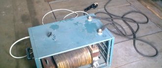
Many years ago, I made a similar regulator when I had to earn extra money repairing radios at a customer’s home. The regulator turned out to be so convenient that over time I made another copy, since the first sample was constantly installed as an exhaust fan speed regulator. https://oldoctober.com/
By the way, this fan is from the Know How series, as it is equipped with an air shut-off valve of my own design. Description of the design >>> The material can be useful for residents living on the top floors of high-rise buildings and who have a good sense of smell.
The power of the connected load depends on the thyristor used and its cooling conditions. If a large thyristor or triac of the KU208G type is used, then you can safely connect a load of 200... 300 Watts. When using a small thyristor, type B169D, the power will be limited to 100 Watts.
PCB Layout Guidelines
In the LM5001 chip, the current sensor comparator and PWM comparator are fast-acting, and therefore they are able to respond to short-duration noise pulses. Components connected to the SW, COMP, EN and RT pins should be located as close to the chip as possible to minimize noise and interference on the PCB traces.
The SW pin of the LM5001 should have short and wide power conductors connecting it to chokes, transformers and capacitors to minimize parasitic inductances that reduce efficiency and increase conducted and radiated noise. It is recommended to install ceramic coupling capacitors between VIN and GND, and between VCC and GND. It is necessary to use short and direct connections to avoid clock jitter due to changing ground potential. It is preferable to use X7R or X5R surface mount capacitors to obtain good frequency properties and limit the influence of temperature and applied voltage on their parameters.
In circuits that use the LM5001, if the pins get very hot during normal operation, a few through holes from the GND pin to the PCB ground plane will help dissipate the heat from the chip. By placing the PCB wisely inside the final product, as well as taking advantage of any airflow available, lead temperatures can be reduced. When using forced air cooling, avoid installing the LM5001 in the airstream behind large components such as input capacitors, inductors, or transformers.
Literature
- Gavrikov V. Texas Instruments at the wheel: TI components for automotive applications // Electronics News. 2014. No. 7. pp. 23–29.
- Zvonarev E., Cheremisov P. Recommendations for designing protection circuits for 12 and 24 V power supply circuits for automotive applications // Electronics News. 2014. No. 8. pp. 12-14.
- Serebryannikov A.V., Malinin G.V., Samsonov A.I. Description and features of the use of the high-voltage pulse regulator microcircuit LM5001-Q1 // Engineering Bulletin of the Don (electronic magazine). No. 4 (T. 31).
- LM5001x High-Voltage Switch-Mode Regulator.
- LM5001-Q1. Automotive Grade 3.1-75V Wide Vin, 1A Current Mode Non-Synchronous Switch Mode Regulator.
- Belov G. A., Serebryannikov A. V., Pavlova A. A. Towards the synthesis of single-circuit control systems for step-down pulse converters // Practical power electronics