LM317 is an adjustable voltage stabilizer. It can be used to create various power supplies. It can be the basis for a current stabilizer, charger, laboratory power supply and even an audio amplifier. In order to use it, it is enough to connect it to one of the wiring diagrams indicated below.
This microcircuit is one of the most popular in the world - all because of the simplicity of its design and operation, its low cost and reliability. The latter is ensured by the presence of protection for short circuit of the terminals and overheating of the microcircuit. LM317 does not require many components as a harness. The microcircuit gained the greatest popularity among radio amateurs.
LM317 regulates voltage linearly, which is its advantage over switching converters. The microcircuit is sold in several housing options, the most popular is the LM317T version in the TO-220 housing. It was developed by Bob Dobkin in 1976 while he was working at National Semiconductor, and has been a hit in ham radio circles ever since.
LM317 circuit
The entire internal structure of the stabilizer can be seen on its diagram, taken in the datasheet. It shows three pins of the circuit: input (power is supplied to this input), regulation and output. At the adjustment pin, the signal voltage is first reduced by a one-way limiter to a stable 1.25V and serves as a reference source, and the current, along with the supply current, goes to a comparator based on an operational amplifier.
Also in the diagram you can see an output stage based on a bipolar transistor, which amplifies the current, and a protection unit against overheating and overcurrent.
To the right of the protection unit there is a current sensor, a drop in which is monitored by the protection in order to prevent damage from short circuits.
Manufacturers and DataSheet
Let's list the main companies that produce LM317T and attach their datasheet:
- Texas Instruments;
- ON Semiconductor;
- Inchange Semiconductor;
- Fairchild Semiconductor;
- Comset Semiconductor.
In domestic stores you can buy products from the following companies:
- STMicroelectronics;
- Tiger Electronic;
- Micro Commercial Components.
Characteristics of LM317
- Maximum input voltage LM317 – 40V
- LM317 output voltage range – 1.2-37V
- Maximum output current for LM317 – 1.5A
- The reference voltage of the microcircuit is 0.1-1.3V
- Minimum load current – 3.5mA
- Output voltage error – 0.1%
- Power dissipation – 20W
- Operating temperature range – 0-125C
- Storage temperature range – -65-150C
- Storage temperature range – -65-150°C
Current stabilizer circuits for LEDs
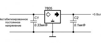
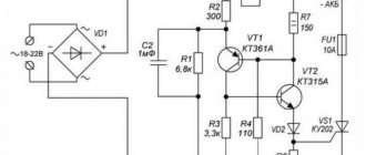
Circuit of the simplest stabilizer
The simplest 12-volt voltage stabilizer can be assembled using this circuit. Resistor R1 limits the output current, R2 limits the output voltage. The capacitors used in this circuit reduce voltage ripple and increase operating stability.
The needs of the motorist will be satisfied by the simplest stabilization mechanism, since the supply voltage in the car network is quite stable.
To make a stabilizer for diodes in a car you will need:
- Chip lm317;
- Resistor as a current regulator for LEDs;
- Soldering and installation tools.
We assemble according to the above diagram
Calculation of a resistor for an LED driver
The power and resistance of the resistor are calculated based on the current strength of the power supply and the current required by the LEDs. For an automotive LED with a power of 150 mA, the resistor resistance should be 10-15 Ohms, and the calculated power should be 0.2-0.3 W.
How to assemble it yourself, watch the video:
The availability and simplicity of the driver design on the lm317 chip allows you to painlessly re-equip the electric lighting systems of any car.
Please rate the article. We tried our best:)
Did you like the article? Tell us about her! You will help us a lot :)
Types of LM317
The microcircuit is sold in several housing options, depending on the need for size, load and connection, as well as the type of circuit installation - everyone can choose the option that suits them best.
The most popular is the LM317T in a TO-220 1.5 Ampere package. This is considered a universal option, as it can be used in surface-mounted as well as surface-mounted applications. A radiator in such a case allows you to remove excess heat and experience more severe loads than its counterparts, and if necessary, it can be attached to a larger radiator.
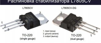
Tsokolevka
We will consider the LM317T pinout in the TO-220 case. For most manufacturers, the terminals are located in the following order: control on the left, output in the middle and input on the right. But in the technical documentation from Micro Commercial Components, the output and input are swapped: on the left is the control, followed by the input and the last output. In the figure below, the outputs are presented in the same order as most companies.
LM317 connection
LM317 has the following pin configuration in different packages:
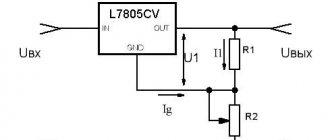
The minimum connection diagram consists of two resistance resistors and three capacitors connected according to the diagram. In accordance with the resistance characteristics, the output voltage will be determined.
The LM317 has two main parameters: its reference voltage, as well as the current flowing out at the trim pin. Reference voltage (Vref) is the voltage that the stabilizer maintains across resistance R1. It is unstable and varies from batch to batch by an average of 0.1V, so for calculations it is better to keep in mind the average value of 1.25V. For serious projects, it is worth measuring it for each instance used. Accordingly, following the diagram, if we close resistor R2, then at the output we will get a reference voltage of 1.25V, and with an increase in the voltage at R2, the output voltage will also increase. Thus, LM317 constantly compares the output voltage through a resistive divider with the reference, therefore, by changing the resistance, we change the output voltage.
The current flowing out at the adjustment (Iadj) is parasitic. According to manufacturers, it ranges from 50 to 100 μA, but in reality it can reach 500 μA. Because of this, for stability of the output voltage, the resistance of R1 should not be higher than 240 Ohms, so that a current of less than 5 mA does not pass through the divider.
All you need is to substitute your R1 value into this formula R2=R1*((Uo/Uref)-1).
Also, don't forget about cooling. The greater the difference between the input and output current, the more the stabilizer will heat up, which will lead to problems with its operation. The parameters described by the manufacturer can only be achieved using additional cooling in the form of a radiator.
How to select components
For a transformer source, first of all, a transformer is selected. In most cases, it is taken ready-made from what is available. This node must produce the required current at maximum voltage. The combination of these parameters is ensured by the overall power of the transformer. For industrial devices, parameters can be found in the reference book. For random transformers, the power can be determined by the core dimensions (in centimeters).
Core area for different types of transformers.
Power is calculated using the formula:
P=S2/1.44 where:
- P-power in Watts;
- S is the cross section in square centimeters.
For practical purposes, the power must also be multiplied by the efficiency. For example, a transformer with a core area of 6 sq.cm. at a voltage of 35 volts and a stabilizer output voltage of 30 volts (the overall efficiency can be taken as 0.75) it is capable of delivering power P=(36/1.44)*0.75=18.75 watts. The maximum current will be I=P/U=18.75/35=0.5 A.
If the transformer passes power, but the secondary winding is designed for a different voltage, it can be removed and a new one wound (if it fits). The number of turns is calculated as follows:
- the number of turns per volt is determined by the formula 50/S, where S is the core area in sq.cm;
- this value is multiplied by the required voltage level.
So, for an area of 6 cm per 1 volt there are 50/6 = 8.3 turns per volt. For a voltage of 35 volts, the winding must have 35 * 8.3 = 291 turns. The wire diameter is calculated using the formula D=0.02, where I is the current in milliamps. For a current of 5 amperes, you need to take a wire with a diameter of 0.02 * = 70 * 0.02 = 1.4 mm.
If a high-power transistor is selected for a linear regulator, the main criterion for application is the collector current. It must cover the load current with a margin. This parameter for common domestic and foreign transistors is given in the table.
| Transistor | Maximum collector current (constant), A |
| KT818 (819) | 10 |
| KT825 (827) | 20 |
| KT805 | 5 |
| TIP36 | 25 |
| 2N3055 | 15 |
| MJE13009 | 12 |
When operating in modes close to the maximum current, transistors must be installed on radiators.
You also need to pay attention to such a parameter as the maximum voltage between the collector and emitter. With an input voltage of 35 volts and an output voltage of 1.5, the difference will be 33.5 volts; for some semiconductor devices this is unacceptable.
The capacity of the oxide capacitor located after the rectifier is selected based on the load. There are formulas for calculating filter parameters, but in practice the approach is simple: the more, the better. There are two restrictions imposed on the capacity:
- capacitor dimensions;
- inrush current per charge, which can be significant with a large capacity.
The output capacitor of the power supply can have a capacity of about 1000 µF.
Typical LM317 circuits
As stated, the LM317 is used to create regulated and unregulated power supplies, however, it can also be used as the basis of a current regulator when creating LED drivers that maintain current in the circuit regardless of the input voltage. The applications described in the datasheet alone are enough to fill a separate book, so we will analyze several of the most popular circuits based on this stabilizer.
Adjustable power supply (1.2-37V)
All that is needed to create it is to replace R2 with a variable resistor, and also add a transformer with a diode bridge to the input. When using it, it is worth considering that the microcircuit has a reference voltage of 1.25V, so it will be minimal for this circuit.
Adjustable power supply (0-37V)
If you need full regulation from 0V, then circuit manufacturers suggest connecting a 10V negative voltage source to the circuit.
You can wind an additional coil on the power supply transformer and connect its leads after the diode bridge as follows:
Or you can use a negative voltage source that will be powered from the main winding.
Thus, you will get a simple laboratory power supply.
LED Driver (Current Stabilizer)
With this circuit you can power fairly powerful LEDs and LED strips. All you need is to know the current consumed and, based on it, select the resistance using the formula.
It uses the same principle as the simplest circuit, but instead of a resistive divider, a current sensor is installed. The more current the load consumes at the output, the greater the voltage drop will be observed across the sensor. It is monitored by the IC and it increases or decreases the voltage to maintain a stable current. Even in the event of a short circuit, the current will remain at the stable level that was set.
Charger
The circuit of this charger is taken from the datasheet and has an output voltage of 6V with a limit of 0.6A. By changing the resistance of resistors R1 and R2, it is possible to adjust the voltage to suit your needs, and with the help of resistor R3 - the current. It is suitable for powering batteries of phones, tools and household appliances.
AC voltage regulation
Since two LM317 can regulate not only positive, but also negative sine wave oscillations, they can be used to create an AC regulator. You can see that the circuit is quite simple and does not require many components:
Types of stabilizers
According to the method of limiting the current, there are two types of devices:
- Linear;
- Pulse.
A linear stabilizer operates on the principle of a voltage divider. It releases a current of a given parameter, dissipating the excess in the form of heat. The operating principle of such a device can be compared to a watering can equipped with an additional drain hole.
Advantages
- affordable price;
- simple installation diagram;
- easy to assemble with your own hands.
Disadvantage: due to heating, it is poorly adapted to work with heavy loads.
A pulse stabilizer , like a vegetable cutter, cuts the incoming current through a special cascade, delivering a strictly dosed rate.
Advantages
- designed for high loads;
- does not heat up during operation.
Flaws
- requires a power source for its own operation;
- creates electromagnetic radiation;
- relatively high price;
- Difficult to make yourself.
Considering the low current in car LEDs, you can assemble a simple stabilizer for LEDs with your own hands. The most affordable and simple driver for LED lamps and strips is assembled on the lm317 chip.
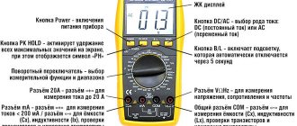
How to test LM317?
Unlike transistors, this microcircuit cannot be checked with a multimeter. This method does not in any way guarantee correct operation due to the large number of internal elements not connected to the terminals. Therefore, if one of them fails, then checking it with a multimeter will be problematic. The easiest way to test the operation of the LM317 is to create a simple stand on a breadboard, and it can be powered only by a battery.
This way, you can quickly verify that an item is in full working order, even if you need to check several pieces.
Main components of a regulated power supply
The transformer power supply in most cases is made according to the following block diagram.
Transformer power supply units.
A step-down transformer reduces the network voltage to the required level. The resulting alternating voltage is converted into pulsed voltage using a rectifier. The choice of its circuit depends on the circuit of the secondary windings of the transformer. The most commonly used full-wave bridge circuit is used. Less often - half-wave, since it does not allow the transformer’s power to be fully used, and the ripple level is higher. If the secondary winding has a center point brought out, then the full-wave circuit can be built with two diodes instead of four.
Full-wave rectifier for midpoint transformer.
If the transformer is three-phase (and there is a three-phase circuit to power the primary winding), then the rectifier can be assembled using a three-phase circuit. In this case, the ripple level is the lowest, and the power of the transformer is used most fully.
After the rectifier, a filter is installed that smoothes the pulse voltage to constant. Typically, the filter consists of an oxide capacitor, parallel to which a low-capacity ceramic capacitor is placed. Its purpose is to compensate for the structural inductance of the oxide capacitor, which is made in the form of a rolled strip of foil. As a result, the resulting parasitic inductance of such a coil worsens the filtering properties at high frequencies.
Next is the stabilizer. It can be either linear or pulsed. The pulse type is more complicated and negates all the advantages of a transformer power supply in the output current niche of up to 2..3 amperes. If you need an output current higher than this value, it is easier to switch the entire power supply, so a linear regulator is usually used here.
The output filter is based on an oxide capacitor with a relatively small capacitance.
Generalized block diagram of a pulse power supply.
Switching power supplies are built on a different principle. Since the current consumed is sharply non-sinusoidal, a filter is installed at the input. It does not affect the performance of the unit in any way, which is why many industrial manufacturers of Economy class power supplies do not install it. You don’t have to install it in a simple homemade source, but this will lead to the fact that devices on microcontrollers powered by the same 220 volt network will begin to fail or work unpredictably.
Then the mains voltage is straightened and smoothed out. An inverter using transistor switches in the primary winding circuit of the transformer creates pulses with an amplitude of 220 volts and a high frequency - up to several tens of kilohertz, in contrast to 50 hertz in the network. Due to this, the power transformer is compact and lightweight. The secondary winding voltage is rectified and filtered. Due to the high conversion frequency, smaller capacitors can be used here, which has a positive effect on the dimensions of the device. Also, in high-frequency voltage filters, it becomes advisable to use chokes - small-sized inductors effectively smooth out HF pulsations.
Voltage regulation and current limitation are performed through feedback circuits, which are supplied with voltage from the source output. If, due to an increase in load, the voltage begins to decrease, then the control circuit increases the interval of the open state of the keys without reducing the frequency (pulse width control method). If the voltage needs to be reduced (including to limit the output current), the time the switches are open is reduced.
Application of LM317
The diagrams given above are only a small part, the basis, compared to what can be done with this stabilizer. It can be used in almost all circuits that require a constant power supply of up to 40 V. Here are some applications described in the official technical document of this chip:
- Personal computers
- Digital cameras
- ECG
- Internet switches
- Biometric sensors
- Electric motor drivers
- Portable chargers
- PoE
- RFID readers
- Appliances
- X-ray machines
As you can see, even the manufacturer himself expects the widest possible use of this element, to say nothing of home-made manufacturers who are ready to present the most unusual circuits using LM317.
Increasing the maximum output current
There are two ways to increase the maximum output current. If you need to get more than 1.5A, then you can either connect several chips in parallel, or connect a power transistor.
In the first case, it is enough to connect resistors with low resistance to the output of the stabilizers. They are needed to equalize currents.
However, it is not always rational to use several chips. Therefore, a transistor comes to our aid. In this case, it will be enough to add it and a resistor as a harness to it.
If the load draws a small current, it will pass through the chip without affecting the transistor. And when it increases, almost all the current will pass through the transistor, leaving a small part of it for the stabilizer. But when using this circuit, there is internal protection inside the LM317 from short circuit.
Analogs LM317
What to do if it is not possible to use LM317? You can use its analogues. The twin brothers of this component are UPC317, GL317, ECG1900 and SG317. The domestic analogue is KP142EH12A, and there is also a KP142EN12 with a fixed voltage.
If the LM317 is not enough power for your project, then you can use more powerful options:
- LM350AT and LM350T – maximum output current 3A and power 25W
- LM350K – current 3 A and power 30 W
- LM338T and LM338K – current 5 A
All these microcircuits have the same pins, so the circuits do not have to be changed in any way.
Safe operation of LM317
It is worth remembering the operational characteristics of the radio component and not using it in critical conditions. The power dissipation according to official information is 20 W, and the difference between the input and output voltages should not exceed 40 V. During soldering, the temperature should not exceed 260 C. It can be used at temperatures from 0C to 125C, and stored from -65C to 150C. All these are officially declared characteristics; in reality, they may differ from instance to instance and be underestimated.
You should not use the element at the maximum and minimum indicated values. With such operation, the level of stability and reliability will drop significantly. It is also highly advisable to use a radiator to remove heat, since otherwise the stated characteristics may not coincide with the real ones.