A 12 volt voltage stabilizer is often used in a car's electrical circuit. Automotive power supplies (battery and generator) of various 12-volt electrical appliances produce direct current with a voltage of 12.5 to 14 V. Such large fluctuations can lead to damage and failure of sensitive and expensive LED strips, fog lights, and radios. In addition to the electrical systems of cars, such devices are used in 12-volt power supplies that are capable of reducing and converting the alternating current of the household electrical network into a direct current more suitable for a number of devices.
Stabilizer selection
In the on-board network of the car, the operating power is approximately 13 V, while most LEDs are suitable for 12 V. Therefore, they usually install a voltage stabilizer, the output of which is 12 V. Thus, normal conditions are provided for the operation of lighting equipment without emergency situations and premature failure.
At this stage, amateurs are faced with the problem of choice: many designs have been published, but not all work well. You need to choose one that is worthy of your favorite vehicle and, in addition:
- will actually work;
- will ensure the safety and security of lighting equipment.
Video
Adjustable voltage stabilizer
Coffee capsule Nescafe Dolce Gusto Cappuccino, 3 packs of 16 capsules
1305 ₽ More details
Coffee capsules Nescafe Dolce Gusto Cappuccino, 8 servings (16 capsules)
435 ₽ More details
Photo printers
The simplest DIY voltage stabilizer
If you have no desire to buy a ready-made device, then it’s worth learning how to make a simple stabilizer yourself. It is difficult to make a pulse stabilizer in a car with your own hands. That is why it is worth taking a closer look at the selection of amateur circuits and designs of linear voltage stabilizers. The simplest and most common version of a stabilizer consists of a ready-made microcircuit and a resistor (resistance).
The easiest way to make a current stabilizer for LEDs with your own hands is on the LM317 chip. The assembly of parts (see figure below) is carried out on a perforated panel or a universal printed circuit board.
The device allows you to maintain a uniform glow and completely eliminate the blinking of light bulbs.
Scheme of a 5 ampere power supply with a voltage regulator from 1.5 to 12 V.
To assemble such a device yourself, you will need the following parts:
- plateau size 35*20 mm;
- chip LD1084;
- RS407 diode bridge or any small diode for reverse current;
- a power supply consisting of a transistor and two resistances. Designed to turn off the rings when the high or low beam is turned on.
In this case, the LEDs (3 pcs.) are connected in series with a current-limiting resistor that equalizes the current. This set, in turn, is connected in parallel to the next similar set of LEDs.
Types of 12 volt stabilizers
Depending on the design and method of maintaining a 12-volt voltage, there are two types of stabilizers:
- Pulse stabilizers, consisting of an integrator (battery, high-capacity electrolytic capacitor) and a switch (transistor). Maintaining the voltage in a given range of values occurs due to the cyclic process of accumulation and rapid release of charge by the integrator when the key is open. According to their design features and control method, such stabilizers are divided into key devices with a Schmitt trigger, equalizers with pulse width and pulse frequency modulation.
- Linear - voltage-stabilizing devices in which zener diodes or special microcircuits connected in series are used as a regulating device.
Pulse
Linear
The most common and popular among car enthusiasts are linear devices , characterized by ease of self-assembly, reliability and durability. The pulse type is used much less frequently due to the high cost of parts and the difficulties of independent production and repair.
Classic model
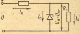
Classic stabilizers are a large class of devices assembled based on semiconductor parts such as bipolar transistors and zener diodes . Among them, the main function of maintaining the voltage at 12 V is performed by zener diodes - a type of diodes connected in reverse polarity (the plus of the power supply is connected to the cathode of such a semiconductor device, and the minus to the anode), operating in breakdown mode. The essence of how these semiconductor parts work is as follows:
- When the voltage of the power source connected to the zener diode is less than 12 V, it is in the closed position and does not participate in adjusting this characteristic of the electric current.
- When the threshold of 12 Volts is exceeded, the zener diode “opens” and maintains this value in the range specified by its characteristics.
Valera
The voice of the construction guru
Ask a Question
If the voltage supplied to the zener diode exceeds that stated as the maximum by the manufacturer, the device very quickly fails due to the effect of thermal runaway. In order for any zener diode model to serve as long as possible, it is recommended to specify the voltage range and current in which it should be operated according to its specifications.
Depending on the connection, there are two versions of the classic stabilizer: linear - the adjusting elements are connected in series with the load; parallel – voltage stabilizing devices are located parallel to the powered devices.
Integral stabilizer
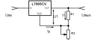
The devices are assembled using small- sized microcircuits capable of operating at an input voltage of up to 26-30 V , delivering a constant 12-volt current of up to 1 Ampere. A special feature of these radio components is the presence of 3 legs - “input”, “output” and “adjustment” . The latter is used to connect an adjustment resistor , which is used to tune the microcircuit and prevent it from overloading.
More convenient and reliable equalizers assembled on the basis of stabilizing microcircuits gradually replacing assembled on discrete elements .
Stabilizer for LEDs on the L7812 chip in cars
The current stabilizer for LEDs can be assembled on the basis of a 3-pin DC voltage regulator (L7812 series). The mounted device is perfect for powering both LED strips and individual light bulbs in a car.
Required components to assemble such a circuit:
- chip L7812;
- capacitor 330 uF 16 V;
- capacitor 100 uF 16 V;
- 1 ampere rectifier diode (1N4001, for example, or a similar Schottky diode);
- wires;
- heat shrink 3 mm.
There can actually be many options.
Connection diagram
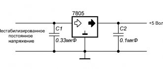
The LM7812 itself is a voltage stabilization circuit and the device is usually connected to it only for this purpose. In fact, nothing else is required to perform this function. Beginning radio amateurs use it in their developments without additional strapping and it works for them, but this is not entirely the right solution.
It is advisable to follow the manufacturers' recommendations, which provide a 7812 switching circuit using two capacitors of 25 V or more. They must be soldered as close to the contacts as possible for more stable operation of the microcircuit. In this case, more capacitance is required at the input than at the output. Failure to comply with this rule leads to instability of the output voltage when there is a sudden change in the load. In addition, such capacitive piping performs protective functions against self-excitation.
The passport states that it is permissible not to install a smoothing capacitor at the output at all. This is possible due to the fact that the role of the power control element inside the 78xx series is performed by an emitter follower based on a Darlington transistor. But as practice shows, a small capacitance is still installed for better suppression of output high-frequency ripples.
An example of how such a scheme works can be seen in a short video.
Connection diagram based on LM2940CT-12.0
The stabilizer body can be made of almost any material except wood. When using more than ten LEDs, it is recommended to attach an aluminum radiator to the stabilizer.
Maybe someone has tried it and will say that you can easily do without unnecessary troubles by directly connecting the LEDs. But in this case, the latter will be in unfavorable conditions most of the time, and therefore will not last long or will burn out altogether. But tuning expensive cars results in a fairly large sum.
As for the described schemes, their main advantage is simplicity. Manufacturing does not require any special skills or abilities. However, if the circuit is too complex, then assembling it with your own hands becomes unreasonable.
Tsokolevka
The LM7812 pinout is as follows. This stabilizer is produced mainly in a plastic housing TO-220. The metal terminals, when looking from left to right, have a purpose: input, ground, output. It is very rare, but identical products are found in TO-263 packaging.
It is worth considering that the metal substrate of all the cases considered is physically connected to the “Ground” pin.
Construction and details
Now let's move on to the design of the device. Diode bridges, a capacitor, resistor R2 and diode VD6 are installed on a circuit board measuring 55x35 mm, made of foil getinax or textolite with a thickness of 1...2 mm (Fig. 9.7).
The following parts can be used in the device. Transistor - KT812A(B), KT824A(B), KT828A(B), KT834A(B,V), KT840A(B), KT847A or KT856A. Diode bridges: VD1...VD4 - KTs410V or KTs412V, VD6 - KTs405 or KTs407 with any letter index; diode VD5 - series D7, D226 or D237.
Variable resistor - type SP, SPO, PPB with a power of at least 2 W, constant - BC, MJIT, OMLT, S2-23. Oxide capacitor - K50-6, K50-16. Network transformer - TVZ-1-6 from tube TVs, TS-25, TS-27 - from the Yunost TV or any other low-power one with a secondary winding voltage of 5...8 V.
The fuse is designed for a maximum current of 1 A. The toggle switch is TZ-S or any other network switch. XP1 is a standard power plug, XS1 is a socket.
All elements of the regulator are housed in a plastic case with dimensions of 150x100x80 mm. A toggle switch and a variable resistor equipped with a decorative handle are installed on the top panel of the case. The socket for connecting the load and the fuse socket are mounted on one of the side walls of the housing.
On the same side there is a hole for the power cord. A transistor, transformer and circuit board are installed at the bottom of the case. The transistor must be equipped with a radiator with a dissipation area of at least 200 cm2 and a thickness of 3...5 mm.
Rice. Printed circuit board of a powerful 220V mains voltage regulator.
The regulator does not need to be adjusted. With proper installation and serviceable parts, it begins to work immediately after being plugged into the network.
Speed controller circuit for an electric motor
To assemble a speed controller for an engine, you will need a PWM pulse generator and a triac to control the engine. The diode and resistor D1 and R1 allow you to reduce the voltage to power the motor, and the capacitor C1 is designed to filter the current at the input of the electrical circuit.
Elements P1, R5 and R3 are voltage dividers with the ability to adjust its values. Resistor R2, which is indicated on the diagram of the electric motor speed regulator, allows you to synchronize the internal blocks of the regulator with the main triac (VT139), on which the speed regulator actually operates.
Below in the figure you can see a visual arrangement of all elements of the speed controller for electric motors. It is imperative to place the elements safely, since the regulator operates from a dangerous voltage of 220 Volts.
Adjustment features
It makes sense to talk about this or that 12 volt regulator only if you provide additional data:
- DC or AC voltage must be regulated;
- what is the maximum current in the load;
- the magnitude of the potential difference in front of the regulator;
- load voltage parameters in the regulation range.
Each of the listed parameters is associated with certain technical solutions that are reflected in the diagram. The general circuit of the regulator is a load that is connected to some device. It is conventionally indicated by a rectangle in the diagram shown below. Inside this rectangle there may be one or another diagram that corresponds to the additional data mentioned above. The simplest regulator is a variable resistor. It allows you to regulate AC voltage without distortion. This resistor is also applicable for direct current.
Circuit with variable resistor.
Elementary diagram of the regulator
Circuit with variable resistor
If the potential difference at the input is significantly greater than 12 volts at the output, energy will be lost in the regulator. The variable resistor will generate heat. To avoid heat loss, it is necessary to use variable inductance on alternating current, which can be LATR. Its throughput is limited, as in a variable resistor, by the design of the moving contact. But if switching is permissible by placing jumpers with reliable contacts between the turns, a significant current can be obtained.
Inductive regulator
Another way to regulate 12 volt alternating voltage with your own hands is to change the inductance of the regulator. To do this, manually change either the gap or the number of turns specifically designed for this. An adjustable welding transformer used to power a voltaic arc is designed according to this principle. If the 12 volt voltage regulator does not have the properties of a stabilizer and is controlled by yourself, the potential difference across the load must be monitored with a voltmeter.
A variable resistor and variable inductance can also be used as a current regulator. In this case, it is necessary to monitor the current in the load with an ammeter. If the voltage parameters at the load are not specified, with the exception of its value of 12 V, you can regulate it with a dimmer. This can be a powerful regulator since it is usually thyristor based. And modern thyristors are produced for a very wide range of potential difference and current.
Main components of a regulated power supply
The transformer power supply in most cases is made according to the following block diagram.
Transformer power supply units.
A step-down transformer reduces the network voltage to the required level. The resulting alternating voltage is converted into pulsed voltage using a rectifier. The choice of its circuit depends on the circuit of the secondary windings of the transformer. The most commonly used full-wave bridge circuit is used. Less often - half-wave, since it does not allow the transformer’s power to be fully used, and the ripple level is higher. If the secondary winding has a center point brought out, then the full-wave circuit can be built with two diodes instead of four.
Full-wave rectifier for midpoint transformer.
If the transformer is three-phase (and there is a three-phase circuit to power the primary winding), then the rectifier can be assembled using a three-phase circuit. In this case, the ripple level is the lowest, and the power of the transformer is used most fully.
After the rectifier, a filter is installed that smoothes the pulse voltage to constant. Typically, the filter consists of an oxide capacitor, parallel to which a low-capacity ceramic capacitor is placed. Its purpose is to compensate for the structural inductance of the oxide capacitor, which is made in the form of a rolled strip of foil. As a result, the resulting parasitic inductance of such a coil worsens the filtering properties at high frequencies.
Next is the stabilizer. It can be either linear or pulsed. The pulse type is more complicated and negates all the advantages of a transformer power supply in the output current niche of up to 2..3 amperes. If you need an output current higher than this value, it is easier to switch the entire power supply, so a linear regulator is usually used here.
The output filter is based on an oxide capacitor with a relatively small capacitance.
Generalized block diagram of a pulse power supply.
Switching power supplies are built on a different principle. Since the current consumed is sharply non-sinusoidal, a filter is installed at the input. It does not affect the performance of the unit in any way, which is why many industrial manufacturers of Economy class power supplies do not install it. You don’t have to install it in a simple homemade source, but this will lead to the fact that devices on microcontrollers powered by the same 220 volt network will begin to fail or work unpredictably.
Then the mains voltage is straightened and smoothed out. An inverter using transistor switches in the primary winding circuit of the transformer creates pulses with an amplitude of 220 volts and a high frequency - up to several tens of kilohertz, in contrast to 50 hertz in the network. Due to this, the power transformer is compact and lightweight. The secondary winding voltage is rectified and filtered. Due to the high conversion frequency, smaller capacitors can be used here, which has a positive effect on the dimensions of the device. Also, in high-frequency voltage filters, it becomes advisable to use chokes - small-sized inductors effectively smooth out HF pulsations.
Voltage regulation and current limitation are performed through feedback circuits, which are supplied with voltage from the source output. If, due to an increase in load, the voltage begins to decrease, then the control circuit increases the interval of the open state of the keys without reducing the frequency (pulse width control method). If the voltage needs to be reduced (including to limit the output current), the time the switches are open is reduced.
Result:
The stabilizer is fully operational and can be used as a voltage stabilizer (subject to the presence of a load) and a current stabilizer.
There are also many different application schemes for increasing the output power, using it as a charger for batteries, etc. The cost of the subject is quite reasonable, considering that offline I can buy one for at least 30 rubles, and in a well-known Russian online store for 19 rubles, which is significantly more expensive than the one being reviewed. With that, let me take my leave, good luck!
The product was provided for writing a review by the store. The review was published in accordance with clause 18 of the Site Rules.
Important points
When using imported integrated voltage stabilizers, it is worth considering some features:
- A capacitor with a capacity of 47 - 220 nF should be connected to the input and output of the device to prevent self-excitation;
- If the capacitor connected to the output has a large capacity and the load current is low, a diode must be connected between the input and output. This will ensure a rapid decrease in the output voltage to the input value;
- for stable operation of the device, the input voltage value must be selected higher than the output voltage by at least 3V;
- devices of the “law-drop” line, characterized by a small voltage difference from input to output, for stable stabilization must be provided with an input voltage that exceeds the output voltage by 0.1 - 0.5 V.
Classic model
Classic stabilizers are a large class of devices assembled based on semiconductor parts such as bipolar transistors and zener diodes. Among them, the main function of maintaining the voltage at 12 V is performed by zener diodes - a type of diodes connected in reverse polarity (the plus of the power supply is connected to the cathode of such a semiconductor device, and the minus to the anode), operating in breakdown mode. The essence of how these semiconductor parts work is as follows:
- When the voltage of the power source connected to the zener diode is less than 12 V, it is in the closed position and does not participate in adjusting this characteristic of the electric current.
- When the threshold of 12 Volts is exceeded, the zener diode “opens” and maintains this value in the range specified by its characteristics.
If the voltage supplied to the zener diode exceeds that stated as the maximum by the manufacturer, the device very quickly fails due to the effect of thermal runaway.
In order for any model of zener diode to serve as long as possible, it is recommended to specify, according to its specification, the voltage range and current strength in which it should be operated.
Depending on the connection, there are two versions of the classic stabilizer: linear - the adjusting elements are connected in series with the load; parallel – voltage stabilizing devices are located parallel to the powered devices.