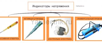
In any technology, LEDs are used to display operating modes. The reasons are obvious - low cost, ultra-low power consumption, high reliability. Since the indicator circuits are very simple, there is no need to purchase factory-made products.
From the abundance of circuits for making a voltage indicator on LEDs with your own hands, you can choose the most optimal option. The indicator can be assembled in a couple of minutes from the most common radioelements.
All such circuits are divided into voltage indicators and current indicators according to their intended purpose.
Indicator circuit
The operation of the device is based on the initial turn-on voltage of the LED. Any LED is a semiconductor device that has a voltage limit point, only exceeding which it begins to work (shine). Unlike an incandescent lamp, which has almost linear current-voltage characteristics, the LED is very close to the characteristics of a zener diode, with a sharp slope of the current as the voltage increases. If you connect LEDs in a circuit in series with resistors, then each LED will start to turn on only after the voltage exceeds the sum of the LEDs in the circuit for each section of the circuit separately. The voltage threshold for opening or starting to light an LED can range from 1.8 V to 2.6 V. It all depends on the specific brand. As a result, each LED lights up only after the previous one lights up.
Laboratory samples
No less interesting are laboratory samples of products made completely differently than everything else. If the indicators shown above use a glass - phosphor - back electrode circuit of the desired configuration, then these ones start from a 1mm thick steel plate as a back electrode, a layer of phosphor, possibly of different colors, and a conductive varnish on top of an unknown brand.
Laboratory samples with conductive varnish under UV light
Yes, I illuminate laboratory samples with a black light lamp because they burn out faster than I can turn them on. They are damp and can hardly withstand even half the operating voltage. Probably, if you dry them in the oven and then laminate them, they will work as they should again. But it is not exactly.
Wire colors and designations
In order to find the phase, neutral and ground wires of electrical wiring without instruments, they, in accordance with the rules of the Electrical Installation Code, are covered with insulation of different colors.
The photo shows the color marking of the electrical cable for single-phase electrical wiring with an alternating current voltage of 220 V.
This photo shows the color coding of an electrical cable for 380V AC three-phase wiring.
According to the presented diagrams, wires began to be marked in Russia in 2011. In the USSR, the color marking was different, which must be taken into account when searching for phase and zero when connecting installation electrical products to old electrical wiring.
What is the difference between N and PE wires in electrical wiring
According to modern requirements of the PUE, in addition to the phase and neutral wires, a yellow-green ground wire must also be supplied to the apartment.
The neutral N and grounding PE wires are connected to one grounded bus of the panel in the entrance of the house. But they perform different functions. The neutral wire is intended for electrical wiring, and the grounding wire is intended to protect people from electric shock and is connected to the housings of electrical appliances through the third contact of the electrical plug. If an insulation breakdown occurs and a phase gets into the body of an electrical device, then all the current will flow through the grounding wire, the fuse links will burn out or the circuit breaker will trip, and no person will be harmed.
If the electrical wiring is laid indoors with a cable without color marking, it is impossible to determine where the neutral conductor is and where the grounding conductor is, since the resistance between the wires is hundredths of an ohm. The only clue can be the fact that the neutral wire is inserted into the electric meter, and the grounding wire passes by the meter.
Attention! Touching exposed parts of a circuit connected to an electrical outlet may result in electric shock.
Prebreakdown electroluminescence
The design of an indicator based on the effect of prebreakdown electroluminescence was created by the French scientist Georges Destriot in 1936.
Electroluminescent indicator from Georges Destriot.
He placed a suspension of zinc sulfide in castor oil between two electrodes and applied high voltage alternating current to them. The glow arising in the dielectric was electroluminescence.
The practical application of the effect begins in 1950, when American researchers Payne, Mager and Jerome proposed the design of a solid-state luminescent capacitor for lighting and created fairly effective phosphor powders.
In the early 60s, there was an explosive growth in the popularity of ELI, primarily in the military sphere, but with the advent of LED indication sources, there was also a rapid decline in interest in them.
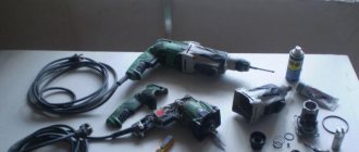
Necessary materials for making an indicator
To make a simple LED device that indicates phase or voltage (approximately), you need to find a working circuit. Then buy or obtain the following parts and tools:
- LED of any type;
- a diode opening with a current of 10-100 mA at a forward potential of 1 V, with a breakdown voltage (reverse) of at least 30-75 V;
- resistor 100-200 kOhm;
- bipolar transistors;
- soldering iron;
- wires;
- metal plate (can be cut from a beer can);
- plastic case, preferably transparent;
- sting, you can take a regular nail.
Chinese soldering iron with USB charging.
But not everything is so smooth
With the advent of other indication sources - primarily LEDs - there was an equally rapid decline in interest in electroluminescence. Unfortunately, this technology has at least two fatal flaws:
- Significant loss of brightness over time. In the first 500 hours, the indicator loses its brightness three times. Then it reaches a plateau and will burn for the next thousand hours with almost no loss of brightness. On the other hand, my prototypes have definitely worked for more than tens of thousands of hours and are still shining.
- High operating AC
voltage. High voltage is not so scary - for example, plasma television panels require 100-150V anode voltage to operate on each line. There are special multi-channel microcircuits, for example, HV507. But ELI is generally a static segment indication and requires AC voltage to operate.
Probe indicators for searching for phase and zero
A device designed to find zero and phase is called an indicator. Light indicators for determining the phase on neon light bulbs are widely used. Low price, high reliability, long service life. Recently, LED indicators have also appeared. They are more expensive and require additional batteries.
On a neon light bulb
It is a dielectric case, inside of which there is a resistor and a neon light bulb. Touching the electrical wiring wires one by one with the screwdriver end of the indicator, you find the phase by the glow of the neon light bulb. If the light bulb lights up when touched, it means it is a phase wire. If it doesn't light up, it means it's a neutral wire.
Indicator housings come in different shapes and colors, but the filling is the same for all. To prevent an accidental short circuit, I advise you to put a tube made of insulating material on the screwdriver shaft. The indicator should not be used to unscrew or tighten the screws with great force. The indicator body is made of soft plastic, the screwdriver shaft is pressed in shallowly and the body breaks under heavy load.
How to choose the right multimeter
A definite recommendation for those who are not interested in radio electronics is a basic digital tester of the 830, 832 or 182 series. Its price is several hundred rubles. The only drawback of such a device is the small current measurement range. However, it is sufficient for household measurements.
If you service the car yourself, you should choose a model with a strong rubberized casing, with a current measurement limit of at least 10 amperes.
Such a device will cost about 1000 rubles, but its safety margin is higher.
Purchasing pointer testers today does not make sense. Perhaps for specific tasks, when it is necessary to monitor certain impulses in real time.
DIY LED voltage indicator: diagrams with description
LEDs have long been used in any technology due to their low consumption, compactness and high reliability as a visual display of system operation. An LED voltage indicator is a useful device needed by amateurs and professionals to work with electricity. The principle is used in the illumination of wall switches and switches in surge protectors, voltage indicators, and test screwdrivers. Such a device can be made with your own hands due to its relative primitiveness.
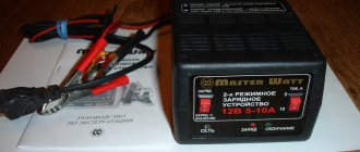
12 volt
The LED indicator circuit for determining the car's charge voltage contains 16 parts.
12 volt probe circuit.
The device has three voltage dividers: resistors, zener diodes and transistors. Their outputs are connected to a three-color LED.
Voltage (in volts) is determined by the color of its glow:
- red – more than 14.4;
- green – 12-14;
- blue – less than 11.5.
The indicator consists of the following parts:
- fixed resistors R1, R3, R5 and R6 – 1, 10, 10 and 47 kOhm, respectively;
- potentiometers R2, R4 – 10 and 2.2 kOhm;
- Zener diodes VD1, VD2 and VD3 for 10, 8.2 and 5.6 V;
- bipolar transistors VT-VT3 type BC847C;
- LED – LED RGB.
Potentiometers R2, R4 set the lowest and highest voltage limits.
Thematic video: How to make a hidden wiring detector with your own hands from scrap materials
The scheme works as follows:
- at a low input potential, transistor VT3 opens and VT2 closes (blue light is on);
- at rated voltage, the current flows through parts R5, VD3, R5 to the green crystal (VT2 is open and VT3 is closed);
- when the potential is high, the divider R1, VD1, R2, VT1 turns on and lights up red.
At 220 volts
To protect yourself from electric shock, you need to place a resistance with a high value at the indicator input. The general scheme of the indicator is as follows:
- one terminal of a 100-200 kOhm resistor is connected to the tip;
- the diode anode and the LED cathode are soldered to the other end;
- their remaining legs are connected to a metal plate.
Scheme of 220 volt current availability.
The diode in the circuit can be of the KD521, KD503, KD522 type (analogues of 1N914, 1N4148). Any craftsman can make a voltage indicator on LEDs with his own hands for 220 V.
AC voltage indicator 220 V
Let's consider the first, simplest version of a network indicator on an LED. It is used in screwdrivers to find the 220 V phase. To implement it we will need:
- Light-emitting diode;
- resistor;
- diode.
You can choose absolutely any LED (HL). The characteristics of the diode (VD) should be approximately as follows: forward voltage, with a forward current of 10-100 mA - 1-1.1 V. Reverse voltage 30-75 V. Resistor (R) must have a resistance of at least 100 kOhm, but not more than 150 kOhm, otherwise the brightness of the indicator will decrease. Such a device can be made independently in a hinged form, even without the use of a printed circuit board.
The circuit of a primitive current indicator will look similar, only it is necessary to use capacitance.
AC and DC voltage indicator up to 600 V
The next option is a slightly more complex system, due to the presence in the circuit, in addition to the elements already known to us, of two transistors and a capacitance. But the versatility of this indicator will pleasantly surprise you. It can safely check the presence of voltage from 5 to 600 V, both direct and alternating.
The main element of the voltage indicator circuit is a field-effect transistor (VT2). The threshold voltage value that will allow the indicator to operate is fixed by the gate-source potential difference, and the maximum possible voltage determines the drop at the drain-source. It functions as a current stabilizer. Feedback is provided through a bipolar transistor (VT1) to maintain the set value.
The operating principle of the LED indicator is as follows. When a potential difference is applied to the input, a current will arise in the circuit, the value of which is determined by the resistance (R2) and the voltage of the base-emitter junction of the bipolar transistor (VT1). In order for a weak LED to light up, a stabilization current of 100 μA is sufficient. To do this, the resistance (R2) should be 500-600 Ohms, if the base-emitter voltage is approximately 0.5 V.
A capacitor (C) is required to be non-polar, with a capacity of 0.1 µF; it serves to protect the LED from current surges. We select a resistor (R1) with a value of 1 MOhm; it acts as a load for the bipolar transistor (VT1). The functions of the diode (VD) in the case of DC voltage indication are pole testing and protection. And to check the alternating voltage, it plays the role of a rectifier, cutting off the negative half-wave. Its reverse voltage must be at least 600 V.
As for the LED (HL), choose a super-bright one so that its glow is noticeable at minimal currents.
Voltage indicator on two-color LED
Another popular indication scheme is one that uses a two-color LED to display the state of charge of the battery or to signal when a lamp is turned on or off in another room. This can be very convenient, for example, if the light switch in the basement is located before the stairs leading down (by the way, do not forget to read an interesting article on how to illuminate the stairs with LED strip).
Before you go down there, you turn on the light and the indicator lights up red, when off you see a green glow on the key. In this case, you don’t have to go into a dark room and feel for the switch there. When you leave the basement, you know by the color of the LED whether the light in the basement is on or not. At the same time, you monitor the health of the light bulb, because if it burns out, the red LED will not glow.
Here is a diagram of a voltage indicator on a two-color LED.
In conclusion, we can say that these are only the basic possible schemes for using LEDs to indicate voltage. All of them are simple, and even an amateur can do them. They didn't use any expensive integrated circuits or anything like that. We recommend that all amateur and professional electricians acquire such a device so that they never endanger their health by starting repair work without checking the presence of voltage.
Instructions for operating the indicator UVNU-10SZ IP
The high voltage indicator UVNU - 10SZ IP and the phasing tube consist of 2 main parts: a working part and an insulating part with a handle. The links are connected to each other by screwing. Safety when working with the pointer and phasing tube is ensured by a ring-shaped stop on the body.
Before use you should:
Carry out an external inspection of the pointer and phasing tube, during which you should pay attention to the absence of cracks, peeling and other defects.
If there is moisture or dirt, remove it with a cloth. If the indicator fogs up in a warm room after storage or operation in the cold, it is necessary to keep it in this room for 15 minutes and wipe it dry with a napkin.
Before using the pointer, you must ensure that it is in good working order.
To do this, touch the probe (hook) with one hand (without gloves) and press the button on the end of the working part of the pointer with the other. Intermittent lighting and sound of the indicator indicate its serviceability.
If the skin resistance is high and the self-test does not work, you need to moisturize your fingers.
At low temperatures (below -25°C), if the self-test does not work, it is recommended to check the indicator as a voltage indicator on an installation that is known to be energized or using a special device for testing voltage indicators (UPUN).
When using the pointer as a voltage indicator from 100 to 1000 V, it is necessary to touch the metal parts of the tail of the working part with your hand and bring the probe (hook) to the current-carrying wire. The appearance of intermittent light and sound signals indicates that the current-carrying part is energized.
Phase-by-phase determination of the presence of voltage is carried out by contact method.
The operator needs to climb onto the support, or determine the presence of voltage by touching the current-carrying part from the ground, if there is an operational insulating rod ШО - 10 - 4 - 6.6, 6.6 m long; in this case, the working part of the pointer is fixed to the thread of the operating head of the rod.
When the probe (hook) touches the pointer to a live part that is energized, bright red flashes simultaneously appear with a frequent intermittent powerful sound signal.
To determine the presence of induced voltage on a de-energized and grounded electrical circuit. installation, you must first check the presence of voltage with a pointer.
After making sure that there is no voltage, it is necessary to re-check the presence of an induced voltage below the threshold (1.5 kV). To do this, it is necessary to separate the working part of the indicator from the insulating part, touching the metal parts of the tail of the working part with your hand (without gloves), and bring the probe (hook) to the current-carrying wire.
The presence of an indication and a sound signal indicates that the current-carrying part is under induced voltage.
When using an indicator with a phasing tube, it is necessary to connect the indicator to the phasing tube with the wire included in the delivery set, and insert the pin of the shunt wire into the hole made on the side of the working part of the indicator.
To avoid damage, the pointer should not be subjected to impacts or shocks.
DIY LED voltage indicator
Checking the voltage in the circuit is a procedure necessary when performing various types of work related to electricity. Some amateur electricians, and sometimes professionals, use a homemade “control” for this - a socket with a light bulb to which wires are connected.
Although this method is prohibited by the “Rules for the Safe Operation of Consumer Electrical Installations,” it is quite effective when used correctly. But still, for these purposes it is better to use LED identifiers - probes. You can buy them in a store, or you can make them yourself.
What is a logic probe used for?
This device is successfully used when it is necessary to perform a preliminary check of the operability of the elements of a simple electrical circuit, as well as for the initial diagnosis of simple devices - that is, in cases where high measurement accuracy is not required. Using a logic probe you can:
- Determine the presence of a voltage of 12 - 400 V in the electrical circuit.
- Determine the poles in a DC circuit.
- Check the condition of transistors, diodes and other electrical elements.
- Determine the phase conductor in the AC electrical circuit.
- Ring the electrical circuit to check its integrity.
The simplest and most reliable devices with which the above manipulations are performed are an indicator screwdriver and a sonic screwdriver.
Electrician's probe: principle of operation and manufacture
A simple identifier with two LEDs and a neon light bulb, which has received the name “arcashka” among electricians, despite its simple device, allows you to effectively determine the presence of a phase, resistance in an electrical circuit, and also detect a short circuit (short circuit) in the circuit. The universal electrician's tester is mainly used for:
- Diagnostics for broken coils and relays.
- Continuity checks of motors and chokes.
- Checking rectifier diodes.
- Definitions of terminals on transformers with multiple windings.
This is not a complete list of tasks that can be solved using a probe. But the above is enough to understand how useful this device is in the work of an electrician.
A regular battery with a voltage of 9 V is used as a power source for this device. When the tester probes are closed, the current consumption does not exceed 110 mA. If the probes are open, then the device does not consume electricity, so it does not need either a diagnostic mode switch or a power switch.
The probe is capable of performing its full functions until the voltage at the power supply drops below 4 V. After this, it can be used as a voltage indicator in circuits.
During the continuity of electrical circuits, the resistance of which is 0 - 150 Ohms, two light-emitting diodes light up - yellow and red. If the resistance value is 151 Ohm - 50 kOhm, then only the yellow diode lights up. When a network voltage of 220 V to 380 V is applied to the probes of the device, the neon lamp begins to glow, and at the same time a slight flickering of the LED elements is observed.
The diagram of this voltage indicator is available on the Internet, as well as in specialized literature. When making such a probe with your own hands, its elements are installed inside the housing, which is made of insulating material.
Often, for these purposes, the housing from the charger of any mobile phone or tablet computer is used. A probe pin should be removed from the front part of the case, and a high-quality insulated cable, the end of which is equipped with a probe or an alligator clip, should be removed from the end part.
Assembling a simple voltage tester with an LED indicator is shown in the following video:
How to make an electrician's tester with your own hands?
Some thrifty hobbyists can find many useful things in their “arsenal,” including an earphone (capsule) for the TK-67-NT telephone.
Another similar device, equipped with a metal membrane, inside which there is a pair of series-connected coils, is also suitable.
Based on such a part, a simple sound probe can be assembled.
First of all, you need to disassemble the telephone capsule and disconnect the coils from each other. This is necessary in order to free their conclusions. The elements are placed in the earphone under the sound membrane, near the coils. After assembling the electrical circuit, we will receive a completely working identifier with sound indication, which can be used, for example, to check the tracks of printed circuits for mutual bridging.
The base of such a probe is an electric generator with an inductive opposite relationship, the main parts of which are a telephone and a low-power transistor (preferably germanium). If you do not have such a transistor, then you can use another one with NPN conductivity, but in this case the polarity of the power supply should be changed. If you cannot turn on the generator, the terminals of one (any) coil must be swapped with each other.
You can increase the sound volume by choosing the frequency of the electric generator so that it is as close as possible to the resonant frequency of the earphone. To do this, the membrane and the core must be placed at an appropriate distance, changing the interval between them until the desired result is obtained.
Terminology
In numerous articles posted on the Internet, you can find the terms “voltage indicator”, “low voltage indicator”, “voltage indicator”. However, often no distinction is made between the areas of their use, and sometimes they are even identified. Let's try to understand this issue.
Numerous rules for the use of electrical protective equipment, which are constantly changing and republished, always use the term “voltage indicator”. In this case, all such devices are divided into bipolar ones, consisting of two bodies connected by a flexible insulated conductor; and single-pole, containing one body. The former operate on active current flowing through both bodies, and the latter operate on capacitive current flowing through the user’s body.
The widely used term “voltage indicator” refers specifically to the second type of indicator. Their early models were produced in the form of a screwdriver with an indicator light in the handle. Modern devices look more like a construction marker (though with a metal contact part at the end).
Why does the indicator light up when you touch the neutral wire?
I have been asked this question many times. One of the reasons is the incorrect use of the LED indicator. How to properly hold the LED probe indicator when searching for a phase is written in the article above.
The second possible reason for this behavior of the indicator is a break in the neutral wire. For example, a circuit breaker installed after the meter on the neutral wire tripped. In old apartments this is not uncommon and is a gross violation of the electrical wiring. It is imperative to remove the machine from the neutral wire or short-circuit its terminals with a jumper.
When the neutral wire breaks, a phase is supplied to it through devices connected to the electrical network, for example, through a switch backlight indicator, a TV in standby mode, any charger, a computer turned off only by the start button and other electrical appliances. The indicator shows this. In this case, the neutral wire can be dangerous and touching it is unacceptable. It is necessary to find and repair a break in the neutral wire, which may also be located in junction boxes.
Mnemonic panel
The coolest indicator in my collection!
A stand with a mnemonic panel and 19-segment IEL-0-IX
Judging by the presence of empty triangles and diamonds, as well as the lack of meaning in the mnemonic diagram itself, I believe this prototype was created solely to demonstrate the capabilities of the plant. This mnemonic panel measuring 30x30cm has more than 100 outputs. I connected drivers to 88 channels and, in principle, you can make a much more beautiful animation than the one that resulted from a bug in the firmware.
19-segment indicators on top - they stood in a large stand at one research institute and for ten years showed the same inscription - ELI-81. According to eyewitnesses, this is the year the indicators were produced and they were burning in the stand as a demonstration of the durability of indicators of this type. I did not connect these indicators to the driver channels, but wired them as they were - with a static inscription. The unburned segments differ significantly in brightness relative to the burned ones - about two to three times, which means they need to be “burned out” for a hundred or two hours to level out the difference.
What is an indicator screwdriver?
This is a tool designed to detect voltage in the electrical network, including hidden ones. Externally, the model may look like a regular flat-head screwdriver with a transparent handle or have a different appearance. However, a probe in the form of a flat bit is required - this is what is used to check the contacts.
Insulation of the handle is also required - the metal part of the device should not come into contact with unprotected human skin, and any metal parts on the handle should not have direct contact with the probe.
They produce products of contact and non-contact types, with different options for sending signals - light, sound, in the form of information on a digital display - as well as with additional functions.
Simple
A working electrical circuit is installed in the case, with a standard set of elements: transistor, resistor, indicator - neon bulbs. The zero phase is the person who closes the contact plate. The tool is not functional - it detects the voltage on the wire, but often does not work when the network voltage is less than 60 Volts. Not suitable for searching for network breaks.
Universal
Portable devices with a wide range of capabilities. An instrument of this type performs contact and non-contact testing, determines open circuits and short circuits using “ringing” of networks, and light and sound warnings help with this. Universal probes are used when repairing or setting up electronic devices and vehicles; they are designed to work with direct and alternating current. The tester operates on a battery, the charge of which is monitored. If the battery loses charge, the universal screwdriver will not work.
The type of indicator screwdriver is selected depending on the intended work. For everyday use, a simple model is sufficient, but for working with electronic devices, choose a universal device.
Method of using an indicator screwdriver
- Non-contact - for a network with voltage up to 600 V. The tip is passed along a wire or electrical appliance that requires testing. If there is voltage, the light will also light up. This is a convenient way to track breaks in the circuit.
- Contact - an indicator screwdriver is used in networks up to 250 V. While holding your finger on the sensor, the tip of the probe is touched to the place that needs to be checked. If there is voltage, the indicator light will light up.
Terms of use
When starting to work with a voltage indicator, you need to make sure that it is intact and operational. The potential difference for which it is intended must be higher than the operating voltage of the electrical equipment being tested. The indicator's next laboratory test date must not be past due.
Before working with a low voltage indicator (LVI), it must be checked for functionality. To check, you can use a connected socket with a voltage of 220 V. A single-pole indicator should determine the phase, and a two-pole indicator should determine the presence of 220 V.
To check the high voltage indicator (HVI), its probe is brought closer to parts of the electrical installation to which high voltage is applied. The alarm should sound. All operations with UNN must be done with dielectric gloves.
Some work in the house can be performed by people without special training, without resorting to the services of professional electricians. Replacing sockets, switches, and repairing table and ceiling lamps do not require high qualifications.
But when performing this work, you must follow safety rules, which require checking that there is no voltage at the contacts of electrical appliances before starting work.
Single-pole voltage indicator
- the simplest and most accessible device for everyone, indicating the presence or absence of a “phase”. Some models are also used to search for breaks in wires, cords and cables. Since some single-pole indicators combine the function of a simple screwdriver, they are called “indicator screwdrivers”, and sometimes simply “indicators”.
The advantage of indicators is that they do not require a second wire to operate. They use current passing from "phase" to "ground" through the pointer and the human body, connected in series. This current does not pose a danger to humans. It is not hampered by the resistance of shoes or the floor material, but you cannot use the pointer while wearing dielectric gloves; it will not work. In practice, there were isolated cases when the indicator screwdriver did not detect the presence of a “phase” in the lamp if the electrician was standing on a dry wooden stepladder.
The ideal indicator for a trader
The question arises, if the EMA is already working at its limit and shows the most relevant price changes, then why do traders not use the EMA all the time? The fact is that for EMA it does not matter at all how long the trend being studied is. Any more or less significant price surge radically changes the direction of the forecast, which can be very misleading and lead to losses.
It turns out that traders do not need to have indicators with low lag - we need some balance between short reaction time and filtering out false emissions. The most famous of these developments is the adaptive moving average - AMA. There are also quite a lot of variations.
Complete advantages of ELI
In the early 60s, during the period of rapid growth in the popularity of ELI (of course, primarily in the military sphere), when they were the only representatives of sign-synthesizing indicators, developers were attracted by such advantages as:
- Uniform, eye-pleasing glow of display elements.
- Possibility of creating indicators of almost any size and configuration.
- Possibility of adjusting the brightness of the glow by changing the supplied voltage.
- Very low consumption - 20-30W per 1 square meter and no heating during operation.
- Wide viewing angle and high contrast.
- High resolution, limited by electrode manufacturing capabilities.
- Mechanical strength.
- And ELI will continue to work where the LCD sucks - for example, at minus 60.
And since the indicator is solid-state, it is ideal for space. They can be seen on the instrument panel of the SOYUZ and ALMAZ spacecraft.
Remote control of the SOYUZ-T spacecraft.
All indicators here are IEL. If you enlarge the photo, you can clearly see seven-segment indicators with characteristic burn-out inscriptions and a brown frame - this is definitely ELI:
Seven-segment IEL on the control panel of the SOYUZ-T spacecraft.
There are also many light fields on the panel that highlight this or that inscription.
Status indicators in operation
To be honest, I don’t know where they were used in civilian life, but ELI as dial backlight is a “feature” of Casio watches.
Operating principle of an indicator screwdriver
Regardless of the type of device, its main idea is to provide a signal about the presence of voltage in the network. In this case, contact models determine the voltage by touching a bare conductor (cable core, contact surfaces of devices, conductive liquid, etc.), while non-contact models “read” the electromagnetic field of the area.
However, in any case, the electrical circuit in a conventional indicator screwdriver must be closed to obtain information - namely, press the contact plate at the end of the product with your finger. A person is also a conductor of electricity, and this is the principle of operation of the device.
All products are divided into groups not only according to design features, but also according to sensitivity. High-quality electronic models are deservedly considered the most accurate, while those with a neon lamp are the most insensitive. The last type of tool accepts voltage from 60 V.
From neon to LED
The solution was to change the glow mode itself from continuous to pulsed.
If you try to estimate the power consumed by a neon lamp, then at a voltage of 100 V and a capacitive current of 20 μA, it will be 100 x 20 μA = 2 mW. If you supply such power to the LED over a time interval, for example, 10 ms, and not a whole second, then it will light up quite well during this interval. After all, at a voltage of 100 V, the current through it will be 0.002 W x 100/100 V = 0.002 A = 2 mA. If you ensure the accumulation of energy in some circuit (for example, in a relaxation generator) for a fraction of a second, and then sharply release it to the LED in 10 ms, then the latter will periodically flash brightly. You will get an LED voltage indicator without a built-in battery.
Read more about types of indicator screwdrivers
The closest in design and capabilities are models with a neon lamp and LED. They differ in the sensitivity threshold (for a diode it is significantly lower than 60V) and the presence of additional capabilities.
A screwdriver with a neon lamp has minimal capabilities - it “can” only detect alternating current in a circuit.
This is what the product looks like disassembled. As you can see in the photo, there are no batteries in this device; there is simply nothing to discharge over time. This screwdriver will work, that is, turn on the light bulb, only when in contact with an electrical circuit containing a voltage of at least 60V and the human body.
Important: the current-limiting resistor in the circuit is provided precisely in order to reduce the current in the circuit being tested to a level that is safe for humans.
The model is used to determine the phase and, by elimination, zero.
In more complex products, batteries may be present, in which case the tester can also be used in non-contact mode - the detector will detect the presence of an electromagnetic field, but also only at a certain voltage level.
An indicator screwdriver with an LED works on a similar principle, only a diode acts as an indicator.
Almost always, such products are equipped with batteries and can operate in contact and non-contact mode. Often, in addition to the light indication, there is also a sound indication. This type of tool is considered universal.
Non-contact indicator screwdrivers work on the principle of detecting “interference”, that is, they search for an electromagnetic field. It is easy to distinguish them from contact options - these products have a plastic probe, not a metal one.
Electronic indicator screwdrivers have a digital display as an indicator and, as a rule, an additional phase indicator.
The principle of operation is the same - when the probe touches a section of the electrical circuit, a message about the voltage level appears on the display. This is precisely the main difference between an electronic device and a conventional one, although for accurate measurements it is still better to use a tester or multimeter.
Option for car
A simple circuit for indicating the vehicle's on-board voltage and battery charge. The zener diode limits the battery current to 5V to power the logic chip.
Variable resistors allow you to set the voltage level to trigger the LEDs. It is better to carry out the setup from a network stabilized power source.
Please rate the article. We tried our best:)
Did you like the article? Tell us about her! You will help us a lot :)
Checking the functionality of the device
Before you start working with a screwdriver, you should make sure that the tool is in good working order.
A simple and quick way to check the device is to insert the conductor probe one by one into each hole of the socket. The electrical socket must be live. If the tool is working properly, then when it hits a phase, the indicator will light up, indicating the voltage at the contact. The absence of a light signal and a sound signal, if it is a universal type, indicates a malfunction of the tester; they cannot test electrical equipment.
Sources
- https://SdelaySam-SvoimiRukami.ru/3867-prosteyshiy-indikator-urovnya-zaryada-batarei.html
- https://YDoma.info/ehlektrotekhnika/electricity-kak-najti-fazu-i-nol.html
- https://svetilov.ru/svetovye-pribory/svetodiody/indikator-napryazheniya
- https://bestcom55.com/indikator-fazy-na-svetodiode-svoimi-rukami/
- https://ues-company.ru/dom/shema-indikatora-fazy.html
- https://ProFazu.ru/provodka/instruments/indikatornaya-otvertka.html
- https://www.vseinstrumenti.ru/ruchnoy-instrument/elektromontazhnyj/probniki-napryazheniya/
[collapse]
A few words about the containers around us
How does a capacitive voltage indicator work? To understand this, let's go back for a moment to electrical circuit theory and remember how a capacitor functions. It has two conductors, or plates, separated by a dielectric. Many people think that capacitors are separate elements of electronic circuits, but in reality the world is filled with capacitors whose presence we usually simply do not notice. Here's an example. Suppose you are standing on a carpet covering a concrete floor directly under a 220-volt light fixture. Although you may not feel it, your body is conducting very little (on the order of a microampere) alternating current because it is part of a circuit consisting of two series connected capacitors. The two plates of the first capacitor are the filament in the light bulb and your body. The dielectric is the air (and possibly your hat) between them. The plates of the second capacitor are your body and the concrete floor (it is a fairly good conductor).
The dielectric of the second capacitor is the carpet plus your shoes and socks. Since the concrete floor is well grounded, as is the neutral wire of the power supply network, a voltage of 220 V is applied to the circuit of these two series capacitors.
Homemade modification
If necessary, you can make an LED phase indicator yourself. First of all, a high-quality wire generator is selected for this. Its output voltage must be at least 12 V. You will also need a damper to assemble the device. There are different types on the market, and they vary quite a bit in sensitivity. If we consider a simple model, then it is more appropriate to select an element with a resistor. A microcontroller for the phase indicator will need a multi-channel type. At the end of the work, the LED is fixed, as well as the clamps.