In some cases, it is necessary to determine that the temperature of an object is within some specified limits, or not below or above a certain limit. Here we propose a circuit for a very accurate four-threshold temperature indicator with LED indication.
Moreover, the thresholds for turning on indicator LEDs can be set for each LED arbitrarily and even in any order without any intrusion into the device circuit. This can even be done directly on site, using a conventional multimeter and a screwdriver to adjust trimming resistors. The fact is that this device measures temperature using the LM235AH sensor, which is essentially a zener diode, the stabilization voltage of which linearly depends on temperature.
Comparator. Description and application. Part 1
This article contains basic information about the operation of voltage comparators built on integrated circuits and can be used as reference material for building various circuits.
In electronics, a comparator is a device that compares two electrical signals and outputs a digital signal indicating whether one input signal is greater than the other. The comparator has two analog inputs and one digital output.
The comparator is usually built on a high-gain differential amplifier. Comparators are widely used in devices that measure and digitize analog signals, such as analog-to-digital converters (ADCs)
Examples of comparator operation are given based on the LM339 (quad voltage comparator) and LM393 (dual voltage comparator) chips. These two microcircuits are identical in functionality. The LM311 voltage comparator can also be used in these examples, but it has a number of functional features.
Voltage Comparator - Open Collector Output
Typically, the output of a voltage comparator is an open collector output.
The open collector output has negative polarity. This means that there is no positive signal at this output and the load must be connected between this output and the power supply.
In some circuits, a load (pull-up) resistor is connected to the output of the comparator in order to provide a high level signal arriving at the input of the next circuit element.
Operational amplifiers (op amps) such as LM324, LM358 and LM741 are not commonly used in electronic circuits as voltage comparators due to their bipolar outputs. However, these op amps can be used as voltage comparators by connecting a diode or transistor to the op amp output to create an open collector output.
Below is the operating logic of a comparator with an open collector output:
Current will flow through the open collector when the voltage at the (+) input is lower than the voltage at the (-) input. And accordingly, current will not flow through the open collector when the voltage at the input (+) is higher than the voltage at the input (-).
Printed circuit board and assembly parts
The printed circuit board is made of single-sided foil PCB measuring 40 by 37 mm, which can be downloaded here. It is designed for mounting DIP elements of the following type:
- MLT-0.125 W resistors with an accuracy of at least 5% (E24 series) R1, R2, R3, R4, R7, R9, R10, R11 – 1 kOhm, R5, R8 – 5.1 kOhm, R6, R12 – 10 kOhm;
- any low-power diode VD1 with a reverse voltage of at least 30 V, for example, 1N4148;
- Zener diode VD2 is low-power with a stabilization voltage of 6.2 V. For example, KS162A, BZX55C6V2;
- LEDs LED1-LED5 – indicator type AL307 of any color.
This circuit can be used not only to monitor the voltage on 12 volt batteries. By recalculating the values of the resistors located in the input circuits, we get an LED indicator for any desired voltage. To do this, you should set the threshold voltages at which the LEDs will turn on, and then use the formulas for recalculating the resistances given above.
Source: ledjournal.info
Equivalent circuit of a voltage comparator with a unipolar power supply
The "voltage comparator" circuit diagram is equivalent to the operation of an operational amplifier, for example, LM358 or LM324, which has two NPN type transistors at the output (see above). Thus, it is possible to make all 4 outputs of the op amp (LM339) open collector. Each such output can withstand a load current of 15 mA and a voltage of up to 50 volts.
The output turns on or off depending on the relative voltages at the positive (+) and negative (-) inputs of the comparator. The comparator's inputs are extremely sensitive and a voltage difference between them of only a few millivolts causes its output to switch.
Equivalent circuit of a voltage comparator with a bipolar power supply
The LM339, LM393 and LM311 voltage comparators can operate with single or dual power supplies up to 32 volts maximum.
When operating with a dual supply, the voltage comparison mode remains the same, except that for most circuits the emitter of the output transistor is connected to the negative supply rail rather than to the common circuit. An exception to this rule is the LM311 operational amplifier, which has an isolated emitter that can be connected either to the negative of a single-polar power supply or to the common wire of a bipolar one.
When working with a bipolar power supply, the input voltage may be higher or lower relative to the common wire of the power supply. In addition, one of the comparator inputs can be connected to a common wire, thus creating a “zero crossing” detector.
Schematic diagram
The considered circuit diagram of a charge level indicator is a simple device that displays the charge level of a 12-volt battery.
Its key element is the LM339 microcircuit, in the housing of which 4 operational amplifiers (comparators) of the same type are assembled. The general view of LM339 and the pin assignments are shown in the figure.
The direct and inverse inputs of the comparators are connected through resistive dividers. 5 mm indicator LEDs are used as a load.
Diode VD1 serves to protect the microcircuit from accidental polarity changes. Zener diode VD2 sets the reference voltage, which is the standard for future measurements. Resistors R1-R4 limit the current through the LEDs.
Description of the comparator operation
The following figure shows the simplest configuration for a voltage comparator, as well as a graphical representation of its operating mode. In this circuit, the reference voltage is half the supply voltage, and the input voltage can vary from zero to the supply voltage. In theory, the reference and input voltages can range from zero to the power supply voltage, but there are actual limits depending on the specific comparator used.
Output signal:
- Current will flow through an open collector when the voltage at the plus (+) input is lower than the voltage at the minus (-) input.
- Current will not flow through an open collector when the voltage at the plus input is higher than the voltage at the minus input.
Checking the voltage stabilizer L7812
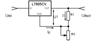
Before starting the test, you need to decide on the value of the input voltage, as well as the pinout of this stabilizer. The datasheet will help with this.
As you can see, the left pin ( input ) needs to be supplied with a positive power supply, and the central one ( gnd ) with a minus power supply. In order to remove the output voltage, you need to connect the red probe of the multimeter to the right terminal ( output ), and the black one to the central one ( gnd ). The input voltage should be no more than 35 V.
For convenience, I solder conductors to the stabilizer terminals.
I will use the power supply I have from some device, since I have not yet assembled the laboratory power supply. There is a marking on the power supply that shows that the plus is in the middle of the connector, and the minus is on its outer part. Pay attention to this point, as sometimes these meanings are opposite.
I secured the free ends of the conductors soldered to the terminals as follows: I twisted the positive one, folded it in half and inserted it inside the connector, and wound the negative one around its body.
Having set the multimeter to measure constant voltage to 20 V and removed the output voltage, I got a value of 12.12 V, which indicates that this stabilizer is working, it stabilized and lowered the input voltage to 12 volts, as it should.
Comparator input offset voltage
Comparators are not perfect devices, and their performance may suffer from the effects of input offset voltage. The input offset voltage for many comparators can be only a few millivolts and can be ignored in most circuits.
Basically, the problem with input offset voltage occurs when the input voltage changes very slowly. The end result of an input offset voltage is that the output transistor does not turn fully on or off when the input voltage is close to the reference voltage.
The following diagram illustrates the effect of input voltage offset resulting from slowly changing input voltage. This effect increases with increasing transistor output current. Therefore, to reduce this effect, it is necessary to ensure the maximum resistance of resistor R4.
The effects of input offset voltage can be reduced by adding hysteresis to the circuit. This will cause the reference voltage to change when the comparator output goes high or low.
Checking voltage stabilizer 17-33G
The 3.3 V stabilizer has a different pinout, as the reference information tells us. Thus, the left pin is the power negative or ground ( gnd ), the center pin is the positive output voltage ( output ), and the right pin is the positive input voltage ( input ). The maximum input voltage is 20V, so my power supply is suitable for testing this component.
Having connected the stabilizer according to the pin markings and checking the output voltage, I got a value of 3.28 V. This stabilizer is also working.
Lately, I have not published articles about device repair, since for the most part I repair the same devices; the repairs are typical and, for the most part, have been described by me previously. Therefore, I decided to dilute the content with such informative articles. I hope the article was useful =)
Input offset voltage and hysteresis
For most comparator circuits, the hysteresis value is the difference in input signal voltage at which the comparator output is either completely on or completely off. Hysteresis in comparators is generally undesirable, but it may be required when it is necessary to reduce sensitivity to noise or when the input signal is changing slowly.
External hysteresis uses positive feedback (POF) from the output to the non-inverting input of the comparator. The resulting Schmitt trigger provides additional noise immunity and a cleaner output signal.
The effect of using hysteresis is that as the input voltage changes gradually, the reference voltage will quickly change in the opposite direction. This ensures clean switching of the comparator output.
The mechanical analogue of hysteresis can be found in a variety of toggle switches. Once the toggle handle is moved past the center point, the spring in the toggle switch moves the relay contacts to the guaranteed position (open or closed).
Hysteresis is an integral part of most comparators, amounting to only a few millivolts and it usually only affects circuits where the input voltage rises or falls very slowly or has voltage spikes known as "noise"...
Battery voltage level indicator using LEDs and LM339 op-amp
Nowadays, a voltmeter on a car dashboard is a rarity. More and more light bulbs with a picture of a battery. This light comes on when the battery is not charging. And yet, you need at least some kind of indicator showing the approximate voltage.
Here is a diagram of a well-tested automotive voltage indicator that can be used for other purposes. The circuit consists of four comparators of the LM339 chip. Accordingly, a four-threshold display device is obtained.
The peculiarity of the circuit is that the voltage threshold for each LED can be set arbitrarily, and this is done very easily and does not require any intervention in the circuit. All you need to do is apply voltage to the circuit and twist one of the trimming resistors so that the corresponding LED lights up when the voltage is applied. In practice, you can set any thresholds for the four LED indicators, and even in any order.
In this case, the lower limit is limited to a voltage of 6V (the voltage at which the LM339 IC still works well), and the upper limit depends on the resistance R6, the value of which in kilo-ohms should be equal to the upper voltage limit in volts. You also need to take into account that the upper voltage should not be more than 30V (maximum supply voltage of the LM339 IC).
The circuit is powered by the measured voltage. The direct inputs of the comparators receive voltage from trimming resistors R2-R5. Each comparator can have its own reference voltage.
To ensure that the reference voltage does not change when the supply voltage changes, it is stabilized by a zener diode VD1. The measured voltage is supplied to the inverse inputs of the comparators connected together through a divider on resistors R6 and R7.
LEDs can be replaced with any indicator ones. If you intend to measure voltages of more than 20V, it is advisable to slightly increase the resistance of resistors R8-R11 so that there is no overcurrent of the comparator outputs. If greater accuracy in setting thresholds is required, the trimming resistors must be multi-turn.
Source: radiostorage.net
Adjustable power supply 2.5-24V from the computer's power supply
How to make a full-fledged power supply yourself with an adjustable voltage range of 2.5-24 volts is very simple; anyone can repeat it without any amateur radio experience.
We will make it from an old computer power supply, TX or ATX, it doesn’t matter, fortunately, over the years of the PC Era, every home has already accumulated a sufficient amount of old computer hardware and a power supply unit is probably also there, so the cost of homemade products will be insignificant, and for some masters it will be zero rubles .
I got this AT block for modification.
The more powerful you use the power supply, the better the result, my donor is only 250W with 10 amperes on the +12v bus, but in fact, with a load of only 4 A, it can no longer cope, the output voltage drops completely.
Look what is written on the case.
Therefore, see for yourself what kind of current you plan to receive from your regulated power supply, this potential of the donor and lay it in right away.
There are many options for modifying a standard computer power supply, but they are all based on a change in the wiring of the IC chip - TL494CN (its analogues DBL494, KA7500, IR3M02, A494, MV3759, M1114EU, MPC494C, etc.).
Fig No. 0 Pinout of the TL494CN microcircuit and analogues.
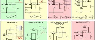
Let's look at several options
execution of computer power supply circuits, perhaps one of them will be yours and dealing with the wiring will become much easier.
Let's get to work.
First you need to disassemble the power supply housing, unscrew the four bolts, remove the cover and look inside.
We are looking for a chip on the board from the list above, if there is none, then you can look for a modification option on the Internet for your IC.
In my case, a KA7500 chip was found on the board, which means we can begin to study the wiring and the location of unnecessary parts that need to be removed.
In the photo the power connector is 220v.
Let's disconnect the power and fan, solder or cut out the output wires so that they don't interfere with our understanding of the circuit, leave only the necessary ones, one yellow (+12v), black (common) and green* (start ON) if there is one.
Lm339 connection circuit in the power supply
The temperature indicator circuit on the LM339N quad comparator is designed to indicate the heating of heat sinks in powerful low-frequency amplifiers and phase power regulators. It can also be used for light signaling of overheating of electric motors, transformers of welding machines, and air-cooled internal combustion engines.
The LM339N integrated circuit is a quad precision voltage comparator. The microcircuit is made in a standard DIP-14 package, has a wide supply voltage range - bipolar from ±1 V to ±18 V, unipolar from 2 to 36 V. The functional diagram of one comparator of the microcircuit is shown in Fig. 2.
Using this chip, it is easy to build, for example, various display units with an LED scale.
In the recent past, the construction of devices with LED scales caused certain difficulties due to the fact that several simultaneously turned on LEDs consumed significant current from the power source, sometimes reaching hundreds of milliamps.
Nowadays, with the advent of ultra-bright LEDs, which shine quite brightly even at a current of less than 1 mA, it is possible to create linear LED scales with simple control, consuming a current of less than 20 mA with 10 or more LEDs turned on simultaneously.
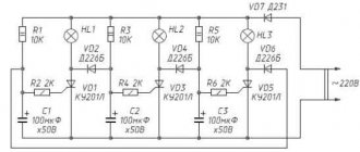
The thermistor R1 with negative TCR works as a temperature sensor - the higher the temperature of its body, the lower the resistance. The device works as follows. Let’s say the voltage at the “+” input, pin 7 of the comparator DA1.1 is greater than at the “-” input, pin 6 of DA1.1. In this case, the comparator output, pin 1, will have a high voltage level, and the HL1 LED will not light up.
When the body of the thermistor R1 heats up, the voltage at its terminals decreases, and the voltage at pin 7 of DA1 also decreases. When the voltage at the “+” input of DA1.1 becomes less than the voltage at the “-” input of DA1.1, at the output of this comparator the high voltage level will change to a low one, the green LED HL1 will light up.
If the engines of the trimmed resistors R2 - R5 are configured so that, starting from R2, the voltage on the engine of each subsequent trimming resistor is less than that of the previous one, then when the thermistor body heats up, the LEDs HL1-HL4 will light up sequentially. First the green LED HL1 will light up, then the yellow HL2, red HL3.
The HL4 LED is flashing red, the flashes of which, according to the plan, should signal critical heating of the controlled object. Zener diode VD1 reduces the supply voltage of the flashing LED to a level that is safe for it. The blue HL5 LED lights up constantly and indicates the beginning of the scale.
Capacitors C2, C3, C4 and inductor L1 act as a power filter for the microcircuit. Resistors R10 - R13 provide a slight negative feedback on the constant voltage, which allows you to observe a relatively smooth ignition or extinguishing of the LEDs as the temperature changes. If you want the LEDs to light up at full brightness and go out instantly, then resistors R10 - R13 must be excluded.
Instead of the LM339N comparator, you can use similar ones LM339AN, LM239AN, LM239A, MC3302N, LM139N. LEDs can be taken from any available super-bright ones, for example, from the KIPD40, L-1513, L-1503, L-7104, L-7113, L-7143 series. The KS175A zener diode can be replaced with D814A1, 2S175ZH, 2S483G, 1N4737A.
When the device supply voltage is less than 9 V, this zener diode does not need to be installed. Oxide capacitors are analogues of K50-35, K53-19. Non-polar - K10-17, K10-50, KM-5. Throttle L1 - any small-sized low-power one.
If missing, you can replace it with a resistor with a resistance of 1.0. 2.2 Ohm. Variable resistors are small-sized imported ones in a closed case. Highly reliable domestic SP4-1 or small-sized multi-turn SPZ-39 are also suitable. Thermistor MMT-1, MMT-4 or other small-sized resistance 4.3. 10 kOhm at 25 °C.
The smaller the size of the thermistor, the faster it will respond to a sudden change in the temperature of the controlled object. If a suitable thermistor is not available, it can be replaced with an assembly of 8. 12 germanium point diodes of the D9, D18 series connected in parallel. The resistance of resistor R1 is selected so that at the nominal operating temperature the voltage at the terminals of thermistor R1 is equal to approximately half the supply voltage.
The LEDs are arranged in the design in the form of a scale, starting with LED HL5, after which HL1 - HL4 are installed in series. If you install a piezoceramic or electromagnetic sound emitter with a built-in generator, for example, HPA24AX, in series with the flashing HL4 LED instead of resistor R17, then the device will emit an intermittent alarm signal in time with the flashes of the HL4 LED.
It is advisable to power the temperature indicator with a stabilized voltage. If, for example, the upgraded amplifier does not have a +12 voltage stabilizer. +18 V, then it can be manufactured additionally, for example, on the KR142EN8V, 7815 microcircuit. With a supply voltage of +15 V and the HL1 - HL4 LEDs are extinguished, the device consumes a current of about 8 mA from the power source.
Voltage indicator on lm339 homemade circuits
LED indicator on universal polycomparator microcircuits containing several general-purpose analog comparators in one housing. The LM339 chip, which contains four comparators with field inputs in one DIP-14 package. Using one LM339 you can make a four-threshold constant voltage indicator.
Figure 1 shows a diagram of such an indicator with a linear measurement dependence. The inverse inputs of all comparators are connected together - their common point is the indicator input. The direct inputs are supplied with a reference DC voltage +Uomax through a resistive divider, which ensures the distribution of this voltage so as to obtain the required measurement law. In this case, the resistors of the divider R2-R5 are chosen to be the same, therefore the dependence is linear.
The maximum value of the measured voltage (the threshold value at which the HL4 LED turns on) is equal to the voltage +Uomax (the maximum reference voltage). It is advisable to stabilize this voltage with at least a conventional parametric stabilizer. The minimum value (threshold at which HL1 lights up) depends on the resistance of resistor R5 or on the value of the minimum reference voltage (Uomin).
For example, if you need to make measurements in some sharply clamped narrow voltage range, for example, from 10 to 11V, then +Uomax should be equal to 11V, and Uomin = 10V, while resistance R5 should be excluded from the circuit. Or choose Uomin equal to zero (as in Figure 1) and set R5 to such a value that the voltage across it is 10V.
Resistances R10-R13 are needed to give the comparator circuits a slight hysteresis, which improves the clarity of the indicator. The indicator scale consists of four LEDs HL1-HL4 connected to the outputs of the comparators through current-limiting resistors R14-R17.
To measure alternating voltage, for example, in an audio signal indication circuit, you can make a detector using diodes or an operational amplifier at the input.
Of course, the circuit shown in Figure 1 is somewhat more complicated than the circuit based on the BA6884 or another similar microcircuit, but this complication is not so significant, especially if you need to obtain some specific characteristic of the measurement law. In addition, this circuit can use almost any currently available analog comparators or operational amplifiers.
The circuit shown in Figure 1 can be easily cascaded to obtain almost any number of measurement thresholds. Figure 2 shows the circuit of an eight-threshold indicator on two LM339 microcircuits, that is, on eight comparators.
Designation and technical specifications
A comparator is a device that compares two different voltages and currents, produces a final power signal indicating the greater of them, while simultaneously calculating the ratio. It has two analog input terminals with positive and negative signals and one binary digital output, just like an ADC. A special indicator is used to display the signal.
The UGO display of the comparator looks like this:
Photo - UGO comparator
Initially, only the integrated voltage comparator (MAX 961ESA, PIC 16f628a) was used, which is known as high-speed. It requires a certain differential voltage within a certain range, which is significantly lower than the mains voltage. These devices do not accept any other external signals that are outside the mains voltage range.
Nowadays, an analog digital comparator (Attiny/ Atmega 2313), which has a transistor input, is much more often used. Its input signal potential is in the range of less than 0.3 Volts and does not rise higher. The device can also be of an ultra-fast type (stereo comparator), due to which the input signal is less than the designated range, for example, 0.2 Volts. Typically, the usable range is limited only by the specific input voltage.
Photo – Comparator
In addition to a simple device, there is also a video spectral comparator based on an op-amp (operational amplifier). This is a device that has a very finely balanced difference between the input and high signal impedance. Due to this characteristic, the operational comparator is used in low-conductivity circuits with low voltage.
Photo - comparator circuit
In theory, a frequency op-amp operates in an open-loop configuration (no negative feedback) and can be used as a low-performance comparator. But at the same time, the non-inverting input (+ V) is at a higher voltage than the inverting input (V-). The high gain output from the op amp causes a low voltage output at the input to the device.
When the non-inverting input falls below the inverting input, the output signal saturates at a negative supply level, then it can still conduct pulses. The output voltage of the op amp is limited only by the supply voltage. The circuit diagram of the op-amp operates in linear mode with negative feedback, using a balanced split power supply (powered by ± VS). Many devices that work with a comparator also tend to record the received data using video, photo or documentary recording. These electronic principles do not work in systems that use open loops and low conductivity components.
Photo - a simple comparator
But the comparator amplifier has several significant disadvantages :
- Op-amps are designed to operate in linear mode with negative feedback. But at the same time, the op-amp has a longer recovery mode;
- Almost all op amps have an internal compensation capacitor that limits the slew rate of the output voltage for high frequency signals. Based on this, this circuit slightly delays the impulse;
- The comparator has no internal hysteresis.
Due to these disadvantages, a comparator for controlling various circuits is, in most cases, used without an amplifier, with the exception of an oscillator.
The comparator is designed for manufacturing processes with limited output voltage that interfaces easily with digital logic. Therefore, it is often used in various thermal devices (thermostat, temperature switch). It is also used to compare signals and resistances of devices such as timers, stabilizers and other circuitry.
Photo - analog comparator
Video: Comparators
Notes from a programmer
Previously, we were introduced to integrated circuits such as the 555 timer, 4026 counter, logic gates, as well as shift registers and decoders. Now it's time to learn about comparators. Despite their apparent simplicity, comparators are much more interesting devices than they might seem at first glance. Read on and you can see for yourself.
An extremely clear picture explaining the operation of a comparator was found in Charles Platt's book Electronics: Logic Circuits, Amplifiers and Sensors for Beginners. With some modifications, this illustration is shown below:
The comparator has two inputs, designated by minus (inverting input) and plus (non-inverting input), and one output. For normal operation, the comparator output must be connected to the positive of the power source through a pull-up resistor. Why this could not be done simply inside the microcircuit will soon become clear.
The comparator is used as follows. A reference voltage is supplied to the inverting input. When the voltage at the second, non-inverting, input is greater than the reference, the comparator output is high voltage. If the voltage at the non-inverting input is lower than the reference voltage, the comparator output is low voltage. Simply put, the comparator compares two voltage values and tells the output which is greater. The comparator inputs can also be used vice versa, in which case the comparator output will be inverted.
A typical microcircuit containing as many as 4 comparators is the LM339. This chip is available both as an SMD component and as a through-hole version. The pinout for LM339 is as follows:
This illustration is taken from the chip datasheet [PDF].
In practice, comparators are most often used in one of the following ways:
Important! By an unfortunate coincidence, the comparator is designated on the diagrams in exactly the same way as the operational amplifier. However, op-amps operate differently from comparators and should not be confused with them. You can usually determine what exactly is used in the circuit by the specified chip name.
The left side of the diagram shows a comparator whose output is connected to a non-inverting input through a potentiometer or resistor. This is the so-called positive feedback. Thanks to it, hysteresis is achieved. That is, if the voltage at the non-inverting input fluctuates in a certain corridor near the reference one, the comparator output will not constantly change. If you remember, the Schmitt trigger (74HC14 chip) does the same thing.
By the way, you can notice that one of the connections on the potentiometer in the positive feedback seems to be superfluous. As Melted Metal explained to me, this is usually done in case of loss of contact between the potentiometer slide and the resistive track.
As for the right side of the diagram, it shows the circuit of a two-threshold comparator. If the circuit's input, designated signal, has a voltage between low and high, the circuit's output produces a high voltage. Otherwise, the output voltage is low.
The following photo shows the first circuit assembled on a breadboard:
The potentiometer on the left sets the voltage at the inverting input, and the potentiometer on the right sets the voltage at the non-inverting input. The potentiometer in the center participates in positive feedback. The voltage at both inputs is displayed using miniature digital voltmeters. Since the voltage at the non-inverting input is higher than the reference voltage, the LED connected to the output of the comparator lights up.
Note that the unused comparators also have high and low voltage inputs. This increases the reliability of the circuit and reduces its power consumption. It does not matter which input is high voltage and which is low voltage. The main thing is that the output of each individual comparator is strictly defined.
I do not present the second assembled diagram here. So you'll have to take my word for it that it works. 
In addition to everything mentioned above, you should keep in mind a couple more important points:
- Do not pass too much current through the comparator. A current greater than 20 mA can burn it out;
- The voltage at the comparator output can be either higher or lower than the voltage at any of the inputs. That is, the output can be powered from a completely different power source. And the power to the microcircuit itself can come from a third one. For the microcircuit to operate correctly, it is only necessary that all these sources have a common ground;
The latter circumstance allows the comparator to be used as a signal level converter. In addition, it has now finally become clear why there were all these difficulties with the external pull-up resistor.
In general, a comparator can be considered as a very simple voltmeter or ADC. In particular, with its help it is not difficult to assemble a Li-Ion battery charge level indicator. If you have an extra photoresistor (see the post My first terrible experiences with Arduino) or a phototransistor, you can make a light sensor based on the comparator. If, instead of a photoresistor, you use a TMP36 type thermometer, you can assemble a device that controls a cooler or air conditioner and can regulate the temperature.
Finally, the comparator can be used as a NOT gate, and also, if you connect the outputs of several comparators, as an AND. From here it is easy to get OR, according to the forum x || y = !(!x && !y), just like any other Boolean function. It goes without saying that other applications can be invented if desired.
What crazy uses of comparators come to mind?
Addition: On the topic of crazy options, see the notes Controlling a bistable relay using one microcontroller pin and Current limiting and/or short-circuit protection circuit.
Tags: Electronics.
Principle of operation
To demonstrate how a high-speed comparator with hysteresis works, you need to take a circuit with two outputs.
Photo - diagram of the comparator operation
The connection diagram, from which you can understand the principle of operation of the comparator, is shown above. Using an analog signal at the + input, called "non-inverting", and the output, called "inverting", the device uses two similar signals of opposite polarity. However, if the analog input is greater than the analog output, then the output will be “1” and this will turn on the open collector of transistor Q8 on the LM339 equivalent circuit to be turned on. But, if the input is at a negative level, then the signal will be equal to “0”, which is why the collector will be closed.
Almost always, a two-threshold or phase comparator (for example, on transistors, without an amplifier) acts on the inputs in logic circuits, and accordingly, operates at the level of a certain power network. This is a kind of transition element between analog and digital signals. This principle of operation makes it possible not to specify the certainty or uncertainty of signal outputs, since the comparator always has some capture of the hysteresis loop (regardless of its level) or a final gain.
Purpose
Why do you need a comparator and how to use it without an amplifier? In most cases, this device is used in simple computer circuits where it is necessary to compare incoming voltage signals. This can be a charger for a laptop or phone, a scale (mass meter), an AVR mains voltage sensor, a timer (composer type lm 358, microcontroller, etc. It is also used by various integrated circuits to control input pulses, providing communication between the signal source and its destination center.
Photo - comparators for computer
The most popular example is the Shimmer trigger comparator. It operates in multi-channel mode, which means it can compare a large number of signals. In particular, this trigger is used to restore a digital signal that distorts communication depending on the voltage level and distance of the power source.
This is an analogue of a standard comparator, just with more advanced functionality, which provides measurement of several incoming signals.
Photo - op-amp comparator
There is also a roughness comparator. This is a device that helps to visually determine the condition of a surface that has already been treated. The use of this device is justified by the need to determine the tolerances of previously processed surfaces.
Programming and Comparator
The comporator is not only used as part of an electrical circuit for PWM, etc., it is often used to create individual programs or their components. For example, the device is often used to create java collections.
- To work, you will need a special Maven program. First, you need to create a project; for full operation, you need an Internet connection. Create a new project, select two components in the structure: comparator and pojo. Availability is checked using the JUnit 4.11 utility;
- Install pom.xml and create a new file. Interrupting the process is unacceptable, so it is very important to save at every stage. Afterwards, a POJO is created and configured, where the necessary settings are specified. The parameters depend on the requirements for a particular library. This could be dates of birth, general information about accommodation, etc.;
- And only after that a comparator is created. This is a class that is used to verify data and distribute it to the required folders. Using this class is necessary if you need to sort certain information according to specified parameters (colors, sizes, dates). This ensures data protection and classification according to a certain principle.
You can buy a ready-made comparator at any radio equipment and electrical equipment store. The price of the device varies depending on its purpose and the number of channels.