Incubation is a practical and simple method of hatching birds. Any poultry farmer knows that for successful incubation of eggs it is necessary to maintain a stable temperature and air humidity. An automatic thermostat helps with this. It heats the elements so that the temperature in the incubator does not change, even if it changes sharply outside.
The number of birds hatched, their health and lives depend on how accurate and reliable the device is. But you don’t have to buy expensive thermostats in stores. Having the necessary parts, skills and knowledge in electrical engineering, you can make a temperature controller with your own hands. Such a device will be no worse than a purchased one.
We recommend a useful article for poultry farmers: DIY chicken brooder.
Why do you need a thermostat for an incubator?
In order for young birds to be hatched efficiently in an incubator, it is necessary to regularly maintain humidity and temperature at optimal levels. Temperature indicators differ depending on the breed of birds and the stage of their incubation; accordingly, they must be regulated. They range from 35 to 39 degrees. And in order to be able to control the temperature, a microcontroller (thermostat) is required.
Many modern factory incubators are equipped with analog thermostats, which need to be frequently adjusted depending on the temperature readings. Most often, alcohol or mercury thermometers are used to maintain temperature.
However, digital temperature microcontrollers have more advantages over analog devices:
- the required temperature is ensured inside the device;
- it becomes possible to control the operation of heating elements;
- based on current indicators, you can control the temperature;
- the process is automated and does not require regular adjustments;
- Electricity is saved because when the required temperature is reached, the heating elements are turned off.
The editors of the site advise you to familiarize yourself with the labeling of imported and Soviet ceramic capacitors.
Advantages and disadvantages
The device of this series compares favorably with its analogues due to its low price and long service life. The manufacturer guarantees uninterrupted operation for 10 years. Users of the Nesushka incubator note the following advantages:
- price-quality ratio;
- lightness and compact design;
- possibility of automated control of the incubation process;
- Great variety of configurations.
Despite the large number of positive aspects, the device also has disadvantages:
- difficulty in washing and disinfection, inability to use ultraviolet light;
- fragility of the structure, the possibility of leakage in the chamber at the bottom of the incubator;
- frequent failures of the electronic system, so you have to switch the device to completely manual mode;
- the need to rotate eggs, since heating is uneven.
You can read about the “Ideal Hen” incubator here.
The advantages include a low price - from 3100 rubles - and compact dimensions. Model Bi-1 with automatic egg turning and digital display weighs 3.3 kg and has dimensions: 67*34*31 cm. The standard package includes two additional grids for quail and goose eggs. Another plus is the presence of an inspection window, which eliminates the need to remove the cover each time.
» alt=»»>
The device also has a number of disadvantages. Users note:
- fragility,
- Unreliability of the egg turning mechanism,
- The need to insulate the incubator during a power outage.
Aquarium heater
Less commonly, such a thermostat was used to maintain a set temperature in aquariums with tropical fish. This need arose due to the fact that the majority of thermal heaters produced for these purposes have a mechanical thermostat combined with a heating element in one housing. And therefore, they maintain their own temperature, and not the surrounding temperature, within specified limits. This works well only in rooms with a stable air temperature, within one or two degrees.
Installation features
- due to the inertia of water, the sensor and the heater must be spaced apart, but within direct visibility (without blocking by plants and decorative elements) from each other;
- due to the electrical conductivity of water, the sensor must be insulated either with means of good thermal conductivity or with a thin layer of conventional sealant;
- It is allowed to use both conventional aquarium heaters and adjustable ones with the temperature set to maximum.
You can find other areas of application for this simple-to-manufacture device. For example, for seedling greenhouses, drying cabinets, various thermal baths. What is your imagination enough for? Only if the load is susceptible to short circuiting is it necessary to add a 1 A fuse.
PS As mentioned above, this simple thermostat was used in incubators before, but now it has been replaced by microcontroller-controlled thermostats that can automatically lower the temperature during the incubation cycle. And the incubators themselves have acquired the function of regulating humidity and turning eggs.
Which is better: buy or make it yourself
There are commercially available thermostats suitable for use in incubators on the market; their price ranges from several hundred to several thousand rubles. If you search well, you can find a very suitable option. You can read how well they work on the forums of poultry farmers and farmers.
Self-production is also quite affordable, and this is the most budget option. All necessary parts can be purchased in online stores with postal delivery. For those who like to do everything themselves, and such people deserve all respect if they take the matter seriously, the rest of the article is intended.
What parts will you need: DIY thermostat
For a temperature sensor, a thermistor is most often used; this is an element that regulates electrical resistance depending on the temperature reading.
Semiconductor parts are also often used:
- Diodes;
- Transistors.
Temperature should have the same effect on their characteristics. That is, when heated, the transistor current should increase and at the same time it should stop working, despite the incoming signal. It should be taken into account that such parts have a big drawback. It is too difficult to calibrate, or more precisely, it will be difficult to associate these parts with some temperature sensors.
However, at the moment the industry does not stand still, and you can see devices from the 300 series, this is the LM335, which is increasingly recommended by experts and the LM358n. Despite the very low cost, this part occupies the first position in the markings and is oriented towards combination with household appliances. It is worth mentioning that modifications of this part LM 235 and 135 are successfully used in the military and industrial sectors. Including about 16 transistors in its design, the sensor is capable of working as a stabilizer, and its voltage will completely depend on the temperature indicator.
The dependency is as follows:
- For each degree there will be about 0.01 V, if you focus on Celsius, then at 273 the output result will be 2.73V.
- The operating range is limited to -40 to +100 degrees. Thanks to such indicators, the user completely gets rid of adjustments by trial and error, and the required temperature will be ensured in any case.
Also, in addition to the temperature sensor, you will need a comparator, it is best to purchase LM 311, which is produced by the same manufacturer, a potentiometer to generate a reference voltage and an output setting to turn on the relay. Don't forget to purchase a power supply and special indicators.
Communities › Kulibin Club › Blog › Electrics: Temperature sensors, we make it ourselves.
Sometimes there is a need for temperature control of some process, be it a car or a national economy. There are many different thermal control schemes, but the sensors usually have an inconvenient design that does not allow for mounting in a controlled environment. Let's talk about sensors.
As a rule, semiconductor devices - thermistors - serve as sensors for measuring circuits:
The case may be different, but inside there will still be about the same droplet with leads.
The second common temperature sensor is the DS1820:
They are often sold as follows:
Inside is the same DS18B20 microcircuit with three pins, even without thermal paste.
Now let's try to implement these radio components into a car, for example, for digital display of coolant temperature or control of electric fans.
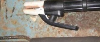
We will need a donor sensor - any suitable thread and cost. In my case, this is the Volga-UAZ sensor TM 106-10
:
We take a drill as a lathe and carefully clamp the sensor into the chuck. Using a metal hacksaw, we cut off the rolling. When the sensor falls apart into its component parts, use a drill to even out the edge of the sensor with a file. We receive a blank housing for introducing our radio component there.
Then you can go in two ways: 1. Pour molten solder into the body, drill a channel in this solder and insert a thermistor there. You can fill the housing cavity with thermal paste and stick the thermistor into it, but tin’s thermal conductivity is several orders of magnitude better than thermal paste, so thermal paste must of course be used, but it’s better to apply a thin layer of it.
The disadvantage of this method is the high inertia of the resulting sensor.
2. Do it the way I do it. Take a telescopic antenna from some old unnecessary device:
If you threw them away before, you did it in vain, because such antennas are a source of wonderful thin-walled brass tubes of different diameters:
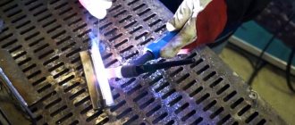
We select the tube most suitable for the thermistor - it should be inserted as tightly as possible into the tube. We measure and again use the drill, cut off the piece of tube we need - it’s better to cut with a needle file. We take our blank body and drill its end according to the diameter of the tube. We tin the end of the body with tin, strip the tube down to brass and also tin it. We insert the tube into the case and solder them to each other, an 80W soldering iron is enough for your eyes. It should look something like this (the end is already sealed with a small piece of copper foil 1mm thick):
We check the resulting sensor housing for leaks. I do it not very technologically - using tongue suction
If everything is in order with the tightness, we proceed to the next stage: installing the thermistor and connector.
Again, we try everything on and cut off the leads of the thermistor so that when installed in the housing, the thermistor is at the end of the tube, or better yet, rests against the end:
The thermistor is now ready for installation. We put a little thermal paste inside the tube, coat the thermistor itself with a little thermal paste and insert it into the tube. After the thermistor has entered the tube under the connector, we place a little pre-prepared poxypol or epoxy plasticine. We press the connector into the polyester and remove the excess. When the Poxypol has completely hardened, you get this nice sensor ready for installation:
And this is how the sensor will stand at its workplace - the measuring part will be completely washed by the working environment:
Well, here’s a picture of a general check of the functionality of the electrical part:
Homemade thermostat: step-by-step instructions
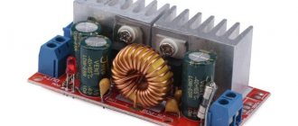
If you have purchased all the necessary components for assembly, all that remains is to review the detailed instructions. We will consider the example of a temperature sensor designed for 12V.
A homemade temperature controller is assembled according to the following principle:
- We prepare the body. You can use old shells from the meter, for example from the Granit-1 installation.
- You select the circuit that you like best, but you can also focus on the board from the meter. The forward stroke marked “+” is necessary to connect the potentiometer. The inversion input with o will be used to connect the temperature sensor. If it so happens that the voltage at the direct input is higher than required, the output will be set to a high level and the transistor will begin to supply power to the relay, and it, in turn, to the heating element. As soon as the output voltage exceeds the permissible level, the relay will turn off.
- In order for the thermostat to operate on time and temperature differences to be ensured, you will need to make a negative connection using a resistor, which is formed between the direct input and output of the comparator.
- As for the transformer and its power supply, you may need an induction coil from an old electric meter. In order for the voltage to correspond to 12 volts, you will need to make 540 turns. It will only be possible to fit them if the diameter of the wire is no more than 0.4 mm.
That's all. These small steps are where all the work of creating a thermostat with your own hands lies. It may not be possible to do it yourself without certain skills right away, but with the help of photo and video instructions you will be able to test all your skills.
Thanks to its simple design, a self-created thermal controller can be used anywhere.
For example:
- For heated floors;
- For the cellar;
- Heating boiler;
- Can adjust air temperature;
- For the oven;
- For an aquarium where the water temperature will be controlled;
- In order to control the temperature value of the electric boiler pump (its switching on and off);
- And even for a car.
It is not necessary to use a digital, electronic or mechanical commercial thermal switch. Having bought an inexpensive thermal relay, adjust the power on the triac and thermocouple and your homemade device will work no worse than the purchased one.
Thermostat circuit - second option
After some thought, I came to the conclusion that it is possible to connect here the same controller as on the soldering station, but with a little modification. During the operation of the soldering station, minor inconveniences were identified: the need to set the timers to 0, and sometimes an interference occurs that puts the station into SLEEP mode
. Considering that women do not need to remember the algorithm for switching the timer to mode 0 or 1, the circuit of the same station was repeated, but only the hair dryer channel. And minor improvements led to stable and “interference-free” operation of the thermostat in terms of control
When flashing AtMega8 firmware, you should pay attention to the new fuses. The following photo shows a K-type thermocouple, which is convenient to mount in the oven
I liked the work of the temperature controller on the breadboard and started final assembly on the printed circuit board.
I finished the assembly, the operation is also stable, the readings in comparison with the laboratory thermometer differ by about 1.5°C, which is basically excellent. When setting up, there is an output resistor on the printed circuit board; I have not yet found an SMD of this value in stock.
The LED models the heating elements of the oven. The only note: the need to create a reliable common ground, which in turn affects the final measurement result
The circuit requires a multi-turn tuning resistor, and secondly, pay attention to R16, it may also need to be selected, in my case it is 18 kOhm. So, here's what we have:
In the process of experimenting with the latest thermostat, more minor improvements appeared that qualitatively affected the final result, look at the photo with the inscription 543
- this means the sensor is disconnected or broken.
And finally we move from experiments to the finished design of the thermostat. I implemented the circuit into the electric stove and invited an authoritative commission to take over the work :) The only thing that my wife rejected were the small buttons on the convection control, general power supply and airflow, but this can be solved over time, but for now it looks like this.
The regulator maintains the set temperature with an accuracy of 2 degrees. This happens at the moment of heating, due to the inertia of the entire structure (the heating elements cool down, the internal frame is temperature equalized), in general, I really liked the scheme in the work, and therefore it is recommended for independent repetition. Author - GOVERNOR
.
Discuss the article THERMOREGULATOR DIAGRAM
Autonomous heating of a private house allows you to choose individual temperature conditions, which is very comfortable and economical for residents. In order not to set a different mode indoors every time the weather changes outside, you can use a thermostat or thermostat for heating, which can be installed on both radiators and the boiler.
Video on the topic
THERMOREGULATOR WITH YOUR HANDS
From early spring to mid-summer - it's time for incubators . Almost everyone who has birds in their backyard uses incubators. With it, it is convenient to breed the required amount of any breed of bird at any time. There is no need to wait for the hen to sit on the nest.
An integral part of any incubator is a thermostat! The hatching of the bird also depends on its reliability and accuracy.
It is not necessary to use a programmable digital expensive thermostat. The thermostat proposed in this article does its job perfectly. A simple and reliable thermostat circuit for an incubator based on one simple and inexpensive K561LA7 microcircuit is proposed below.
Simple , because a bunch of transistors were replaced by one microcircuit.
Reliable , because the circuit uses some points:
- To drop the voltage from 220V to 9V, a resistor is used, not a capacitor (as is often the case in other circuits). It's much more reliable.
- The lamps are connected in series-parallel, which is also more reliable than just parallel connection.
- If the contact of the variable resistor “temperature” is poor, the lamps will turn off, and not vice versa.
- The K561LA7 microcircuit (as practice has shown) is more reliable than an op-amp or PIC.
The first element DD1.1 contains a threshold element, which changes its position at the output from 1 to 0 at a given temperature. “Temperature” regulator changes this threshold.
on the second element DD1.2 for proper operation of the thyristor.
The third element DD1.3 is an adder.
The fourth element DD1.4 is free and can be used (as a last resort) to replace one of the other elements in the event of its failure.
K561LA7 chip can be replaced with its imported analogue CD4011B.
The current consumption of the 9V circuit is 5 mA, the temperature of R13 is approximately 60 - 70 degrees. - this is the normal mode of the resistor.
Pulses arriving at the transistor open it, which subsequently contributes to the opening of the thyristor.
Thyristor (T122 or KU202N,M,L) is a powerful switching element of the circuit. A thyristor (if KU202N,M,L is used) without a radiator is capable of switching a load of up to 300 W. Usually this is enough. If your load exceeds this value, then the thyristor must be placed on the radiator. Maximum value 1000 W. You can also install a more powerful thyristor - T122.
Calculating the load for an incubator is easy . We turn on the heaters (lamps) through this temperature regulator to full. And we control the temperature with a thermometer. Even at full (the lights do not turn off), the temperature in the incubator should not rise above 50 degrees.
Since, during operation, the lamp filaments sag greatly and burn out. There is a danger of the thyristor failing. Therefore, it is recommended to connect the lamps in series-parallel, as indicated in the diagram, for a longer service life of the lamps and the circuit.
Since there is very high humidity in the incubator, you need to put a piece of tube on the temperature sensor - the thermistor and fill it with waterproof glue or sealant on both sides. It is better to do this several times with a period of several hours after drying. The end of the thermistor can be left on the surface for greater sensitivity.
The circuit is universal for the choice of thermistors. The value of the thermistor is suitable within a wide range. I tried from 1 kOhm to 15 kOhm that I had available. Others will do too. The correct operating mode must be selected by dividing by R2, R3. You can select R3 using the table below.
Tags: temperature sensor, sensor manufacturing
Comments 153
I installed exactly the same one on a double-circuit boiler. The third season is already plowing. The power supply is from an antenna amplifier. Did you have a controller with a sensor?
no, as far as I remember, I bought the sensor separately at Chip and Deep
But in general, then I assembled everything I had planned on the DS18B20
And this option: a thermocouple attached to the pipe and a simple multimeter in temperature measurement mode
Tell me, what kind of display board is it? Homemade?
no, not homemade - a friend bought a “bunch for a heel” on Aliexpress and gave one to me:
Have you ever thought of stirring up such a thing yourself?
Thought. On the DS1820 sensor. But it so happened that I went to visit a friend, we started talking over a glass of tea, I told him what I wanted to do, and he took this device from the shelf and gave it to me. Now the need for independent production seems to have disappeared. But I’ve already done it according to this scheme before and I have everything for it:
Dallas works better compared to thermistors, and digitally. However, the range is small.
why is it too small? More than enough for use in cars.
Dallas, in principle, has a better measurement range. But the upper limit is critical. The thermistor, as far as I remember, is not reliable. Although if the potential sits at 12 volts, it works. But Dallas needs stable power.
Can you tell me more about what the top bar is critical? I heated the sensor to more than 120 degrees with a hairdryer, it seemed to work after that.
The upper temperature range seems to be 125 degrees in Dallas. That is, -50 and +125. And if you need a controlled temperature above 125, then Dallas will not cope. In general, its accuracy is normal, but there is a delay of 0.5-1 seconds. There is a 3-wire connection, it is possible to connect via 2 wires. There will be a delay and the range will be less.
I know about these connections, just for fun I tried to heat the sensor with a hairdryer, I was able to see 127.9 as much as possible on it, beyond zero, when it cools down it returns to normal)
no, this is already a proven technology. I only got confused by taking pictures of everything, formulating it and posting it here)
I understand that it’s used, but is it really worth the effort given the relatively low cost of the sensor? Although of course there are rare and expensive sensors...
no, it’s not a matter of cost, it’s a matter of fitting a Chinese sensor into the required structure. You need to regulate the temperature of the water, for example, with a boiler - you just can’t put the sensor in the water; you have to screw it in somehow, so you need a housing.
By the way, what a cool idea...listen, how much would the cheapest sensor like this cost? If only it would open the circuit like a thermostat and then there would be no price...
I understand that it’s used, but is it really worth the effort given the relatively low cost of the sensor? Although of course there are rare and expensive sensors...
Well, look - I, for example, have a Bosch Mono-Jetronic, according to all the tables, DTVV and DTOZH should (at the same air temperature and coolant) give the “brains” the same resistance. At the same time, the DTVV is quite adequate, but cannot be replaced (due to design features). And the DTOZH is “buggy”; when the readings differ, the ECU begins to “adjust”, because can’t figure out who to believe (DTOZH or DTVV)! I bought 4 (FOUR) different sensors - they all give different resistance at the same temperature! And with the technology described above, it is possible to select a cheap thermistor for almost any resistance value at a given temperature! Yes, whatever, you can replace BOTH thermistors (by selecting the required resistance) with both DTOZH and DTVV! And this will help solve several problems with “glitches” of the electronic power system at once! Moreover, the price of Chinese thermistors, consumables, etc. There is no comparison with “branded” sensors (which sometimes cannot be replaced, or they cost like an airplane wing)! Am I explaining this clearly? )))
Description of the operation of the aquarium thermostat
The circuit diagram of the regulator is shown in Figure 5.1.1. The circuit is implemented on an integrated comparator DA1 brand 554CA3. The role of a power radio element is played by thyristor VS1 of the KU202M brand. The DA1 chip is powered by a stabilizer based on radio elements VD1, R11.
The reference voltage from the divider R1, R2 is suitable for the direct input of the comparator. Thanks to potentiometer R2, it is possible to change the size of the reference voltage, and therefore the temperature at which the comparator switches.
The opposite input of the comparator (pin 4 of DA1) receives a measured voltage, the size of which is set by the resistance of thermistor R4 (water temperature sensor in the aquarium). If the voltage at pin 4 of DA1 is greater than the voltage at its pin 3, a log appears at the output of the microcircuit. 0. A current flows through the +12 V electrical circuit - R8 - pin 9, 2 IC1 - R9, which unlocks the thyristor VS1 and turns on the LED HL1.
When thyristor VS1 is unlocked, the power circuit of the water heater in the aquarium is closed and it heats the water. If the water temperature increases, the resistance of thermistor R4 becomes less. When the voltage at pin 4 of DA1 is lower than the voltage at pin 3, the comparator changes its output state and the thyristor turns off. As a result, the heater is turned off from the network.
How to setup
To configure the device, you must either have a reference device or know the voltage rating corresponding to a particular temperature of the controlled environment. Individual devices have their own formulas showing the dependence of the voltage on the comparator on temperature. For example, for the LM335 sensor this formula looks like:
V = (273 + T) • 0.01,
where T is the required temperature in Celsius.
In other schemes, adjustment is made by selecting the values of adjusting resistors when creating a certain, known temperature. In each specific case, our own methods can be used, optimally suited to the existing conditions or equipment used. The requirements for the accuracy of the device also differ from each other, so in principle there is no single adjustment technology.
Description of the circuit operation
The temperature sensor is a thermistor R1 with a nominal value of 150k, type MMT-1. Sensor R1 together with resistors R2, R3, R4 and R5 form a measuring bridge. Capacitors C1-C3 are installed to suppress interference. Variable resistor R3 balances the bridge, that is, it sets the temperature.
Diagram of a homemade thermostat part
If the temperature of temperature sensor R1 drops below the set value, its resistance will increase. The voltage at input 2 of the LM311 microcircuit will become greater than at input 3. The comparator will work and its output 4 will set to a high level, the voltage applied to the electronic timer circuit through the HL1 LED will cause the relay to operate and turn on the heating device. At the same time, the HL1 LED will light up, indicating that the heating is turned on. Resistance R6 creates negative feedback between output 7 and input 2. This allows you to set hysteresis, that is, the heating turns on at a temperature lower than it turns off. Power is supplied to the board from the electronic timer circuit. Resistor R1 placed outside requires careful insulation, since the thermostat’s power supply is transformerless and does not have galvanic isolation from the network, that is, dangerous mains voltage is present on the elements of the device. The procedure for manufacturing the thermostat and how the thermistor is insulated is shown below.
Electronic homemade products for household use
materials in category
S. ABRAMOV, Orenburg Radio, 2002, No. 9
The thermostat, the diagram of which is shown in Figure 1, is intended for a small-sized incubator and maintains a temperature in it set in the range of 20...50°C. The sensor is the thermistor RK1, which together with resistors R1, R3, R4, R6 forms a measuring bridge. The balance of the bridge at a given temperature is achieved with a variable resistor R6. Capacitors C1 and SZ are noise suppressing capacitors.
If the temperature is higher than the set one, the polarity of the bridge unbalance voltage at the input of comparator DA1 is such that the output transistor of the latter is closed, otherwise it is open. Pin 9 of DA1 (collector of the output transistor) is supplied with a pulsating voltage from the output of the half-wave rectifier on diodes VD1 and VD2. The amplitude of its pulses is limited by the zener diode VD3. At a temperature below a given one, pulses from pin 2 of DA1 (emitter of the output transistor) arrive at the control electrode of the thyristor VS1, opening it in the positive half-cycles of the mains voltage. Resistors R7-R16 connected in parallel serve as a heating element.
Circuit VD4C4 converts pulsating voltage into constant voltage. After the DA2 stabilizer, it powers the measuring bridge and comparator.
Thermostat printed circuit board with parts layout
Construction details
The following replacements of elements are possible: comparator K554SAZ (DA1) - to 521SAZ, taking into account differences in the assignment of pins, integrated stabilizer KR142EN5A (DA2) - to any other with an output voltage of 5...6 V and a load current of at least 50 mA, thyristor KU201K (VS1) - for KU201L, KU202K-KU202N, diodes KD105 (VD1, VD2, VD4) - for any silicon with a permissible current of 150...
300 mA, zener diode D814D (VD3) - on D814G. Thermistor ST1-17 is used as RK1; its rating (resistance at room temperature) can reach 4.7 kOhm; you just need to increase the ratings of the measuring bridge resistors by the corresponding number of times. Variable resistor R6 - SPZ-4a. Oxide capacitors - K50-35 or similar. Capacitor C2 - K73-17 for a voltage of at least 400 V.
The incubator is a foam box with dimensions 600x600x300 mm. Holes with a diameter of 6...10 mm are drilled in its bottom for air access and grooves are pressed into which water is poured at a temperature of 43°C (when pouring) to maintain the required humidity. A metal grid for laying eggs is installed inside, a thermistor RK1 and a heating element made of MLT-2 resistors (R7-R16) are placed. The inertia of the heater can be reduced by assembling it from MLT-0.5 resistors. Their number and ratings are selected in such a way that the total resistance remains the same and the permissible power dissipated by one resistor is not exceeded. An ordinary incandescent lamp or heating element with a power of 20...30 W for a voltage of 110...127V can also serve as a heater.
In the room where the incubator is located, a constant supply of fresh air is necessary, and the temperature should not go beyond 20...25 °C. The incubator should not be exposed to direct sunlight.
General concept of temperature controllers
Devices that record and simultaneously regulate a given temperature value are more common in production. But they also found their place in everyday life. To maintain the necessary microclimate in the house, water thermostats are often used. They make such devices with their own hands for drying vegetables or heating an incubator. Such a system can find its place anywhere.
In this video we will find out what a temperature regulator is:
https://youtube.com/watch?v=bXNiBuC6LSM
In reality, most thermostats are only part of an overall circuit, which consists of the following components:
- A temperature sensor that measures and records, as well as transmits the received information to the controller. This happens due to the conversion of thermal energy into electrical signals recognized by the device. The sensor can be a resistance thermometer or a thermocouple, which have metal in their design that reacts to changes in temperature and changes its resistance under its influence.
- The analytical unit is the regulator itself. It receives electronic signals and reacts depending on its functions, after which it transmits the signal to the actuator.
- An actuator is a kind of mechanical or electronic device that, when receiving a signal from the unit, behaves in a certain way. For example, when the set temperature is reached, the valve will shut off the coolant supply. Conversely, as soon as the readings drop below the specified values, the analytical unit will give a command to open the valve.
Areas of application of the thermostat
Basically, this device was used for thermal stabilization of poultry incubators. Where the heating elements were played by low-power 60 W electric light bulbs, connected in parallel in groups of 4, 6 and 8, depending on the size of the incubator and the number of eggs being incubated.
How to install an incubator heater
- the lamps should be evenly located above the surface of the eggs, at a distance of 25-30 cm from their surface;
- the thermistor should be as close as possible to the surface of the eggs, but not touch them;
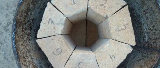
- Instead of light bulbs, you can use other heaters, but with a low heat capacity, for example, tungsten wire stretched over a tetrahedron-shaped ceramic frame.
How does a digital thermostat work?
Accurate temperature control is best achieved through the use of digital thermostats. They differ from simple designs in the method of signal processing. The voltage is removed from the sensor, passes through the analog-to-digital converter and enters the comparative side. The digitally obtained initial temperature value is then compared with that received from the sensor, after which the control device receives the appropriate command.
Thanks to this method, the measurement accuracy is increased and is almost independent of ambient temperature or interference. Sensitivity and stability are most often limited by the system capacity and sensor capabilities. The digital signal easily allows you to display the temperature on a special display.
Review of digital thermostat models
The Ringder THC-220 thermostat is an inexpensive model that is perfect for a small DIY home incubator.
Thanks to the external block of sockets and temperature control from 16 to 42 degrees, it can be used in the off-season, and not just in summer. Technical characteristics of the device:
- humidity and temperature in the sensor area are displayed on a special display;
- the displayed temperature varies from -40 to 100 degrees, and humidity – up to 99 percent;
- one or another mode is displayed as a specific symbol;
- the temperature setting step is 0.7 degrees;
- The timer has a 24-hour format and is divided into night and day;
- one channel has a load capacity of 1200 W;
- the temperature in a large room can vary by up to one degree.
Another factory model of the digital controller is XM-18. In Russia you can buy it with an English or Chinese interface. It is more complex and costs more than the previous device.
It's not difficult to deal with him. Depending on the required temperature inside the incubator, special keys can control the factory program. The front panel has screens that display temperature, humidity and additional parameters. Active modes are indicated by LEDs; in case of dangerous deviations, light and sound alarms are triggered.
Characteristics of XM-18:
- temperature operating range - from 0 to 40.5 degrees, probability of deviation - 0.1 degrees;
- the permissible load along the heater channel is 1760 W;
- permissible load on the humidity, alarm and motor channels – 220 W;
- There is an interval of up to 999 minutes between turning eggs;
- cooling fan runs 999 seconds between permissible periods between inversions;
- indoor temperatures are allowed from -10 to 60 degrees, and relative humidity is up to 85 percent.
When choosing a factory thermostat with a temperature sensor for an incubator, it is very important to consider its capabilities. If it is small and made by yourself, then a device that controls only humidity and temperature will be enough for you, and additional capabilities are needed for more complex models for industrial needs
Ready-made thermostats from equipment manufacturers
| Thermostat model name | Price | Its description |
| Dream – 1. | 2500 – 3000 rub. | The most popular model of all thermostats. It has a turning function and controls not only the temperature sensor, but also the humidity sensor. Works in absolutely any conditions. It has a digital display. |
| Aries. | From 4000 rub. | PID is a regulator, not originally intended for use in incubators. But craftsmen have long found a use for it. Typically used for large-scale (production) purposes. |
| TCB4S-24R | From 3500 rub. | It has a PID regulator, has two digital displays, and is distinguished by its high accuracy in readings. |
| LILYTECH ZL-6210A (7A) | from 1200 rub. | Waterproof thermostat with a current limit of seven amperes. |
| LILYTECH ZL-7801С (temp + humidity) | From 2500 rub. | Thermostat with humidity control and timer. |
| Ringder RC-113M (PID controller) | From 1500 rub. | Pid controller has precise control. |
| XM-18 mode 3 | From 4500 rub. | There is a display. This is a professional model that allows you to track all indicators, built on avr. |
| Ringder RC-112E 30A | From 1200 rub. | Can be used for any animal premises (cages and terrariums). Can be used in outdoor showers and other places; Where autonomous control and temperature control is required. Operates from a standard 220 Volt network. |
Where can I buy
You can buy the most ordinary thermostat, Chinese. You can do this either in our stores or order it from China. You will only need to configure it, because the default settings will be factory settings. The main positive quality of a Chinese thermostat will be its cost.
You can buy such thermostats with an air temperature sensor for an incubator on the Internet or in any other offline stores, a list of verified ones:
| № | Stores (Links to stores): |
| 1 | Minifermer.ru (https://minifermer.ru/category_10.html) |
| 2 | Tiu.ru (https://tiu.ru/Termoregulyator-dlya-inkubatora.html) |
| 3 | Mirinkub.ru (https://mirinkub.ru/catalog/termoreguliatory) |
| 4 | Aliexpress (https://ru.aliexpress.com/popular/thermostat-for-incubator.html) |
You can also look for advertisements for sale: “I’m selling a thermostat for an incubator,” or post your own: “I’ll buy a mechanical thermostat or an electronic thermostat for an incubator,” maybe someone is selling a homemade thermostat for an incubator. But many would like to know how to make a thermostat for an incubator with their own hands?
A little theory
Any thermostat structurally includes three main blocks:
Theoretically, a temperature sensor can be represented by a set of four resistances, among which three resistors will be represented by elements with constant electrical parameters, and the fourth by variable ones. They are assembled into a measuring half-arm circuit shown in Figure 1 below:
The diagram shows the principle of connecting resistors to obtain a temperature sensor. As you can see, resistance R2 is variable and changes its physical value in accordance with changes in ambient temperature. When the same supply voltage is supplied to the thermostat, when the resistance in the arm changes, the current in the circuit will increase.
Based on the changes, temperature fluctuations are analyzed, as a result of which the working element causes the thermostat to operate and subsequently turn off or turn on the equipment.
To measure the resistance of resistors, a microcircuit operating in comparator mode is installed as a logical element. Its task is to compare the electrical signals in the two arms. An example of a temperature controller circuit is shown in the figure:
Here, the U1A microcircuit block receives signals from the temperature meter at inputs 2 and 3. When the response temperature is reached, different currents will begin to flow in the arms, and the comparator will send a signal to turn on to the control element of the electronic thermostat.
When the thermometer sensor cools down, the current in the arms of the thermostat will equalize, and the electronic unit will issue a control signal to turn off. The above electronic circuit operates in two stable states - off and on, alternating operating modes occurs in accordance with a given logic.
This thermostat circuit is used in the operation of a personal computer cooler; receiving power from the power supply, the current in the arms is compared. When the power supply overheats, the thermostat will switch the transistor to the opposite state and the fan will start.
This principle can be used not only in fans, but also in a number of other devices:
- to control the operation of electric heating based on temperature readings in the room;
- to set the temperature level in a homemade incubator;
- when connecting a heated floor to control its operation;
- to set the temperature range of engine operation, with forced cooling or shutting down the system when the temperature limit is reached;
- for soldering stations or hand soldering irons;
- in cooling systems and refrigeration equipment with the logic of reducing temperature within certain limits;
- in ovens and stoves for both household and industrial purposes.
The scope of application of the thermostat is not limited in any way; wherever you want to control the temperature level in automatic mode with power management, such a device will be an excellent assistant.
Single-channel transistors for thermostats
Do-it-yourself incubator thermostats with single-channel transistors are quite easy to assemble. First of all, a microcircuit is selected for assembly. Experts recommend using rotary microcontrollers for lamprey. To increase current conductivity, only one connector is needed. It is used of the distribution type. In some cases, transistors are installed with insulators. However, most often they are used without them. The maximum resistance in the system never exceeds 50 Ohms. On average, the output voltage parameter is at the level of 5 V.
Assembly and adjustment
When assembling the thermostat, it is necessary to ensure a high-quality connection of all electrical contacts, especially in the power section.
When using a temperature sensor LM-335 or a similar (calibrated) one, there is no need to configure the device, as already noted.
If a thermistor or any semiconductor element is used as a temperature sensor, then adjustments cannot be avoided. It is most convenient to carry it out using a digital thermometer, for example, brand TM-902C.
The sensors of the thermometer and thermostat must be connected using adhesive tape or electrical tape and placed in environments with different temperatures. In this case, each time you need to gradually change the resistance of the variable resistor until the device works. At this moment, you need to record the readings of the digital thermometer and make a corresponding mark opposite the current position of the variable resistor knob.
Selecting a regulator circuit
If you take factory products as a basis for the manufacture of a thermostat, you may encounter insurmountable difficulties in assembly, and especially in setting up such products.
To avoid unnecessary problems, it is best to choose a product design that can be manufactured at home.
The main criterion for any type of thermostat is to ensure high sensitivity to changes in internal temperature inside the incubator, as well as an immediate response to these changes. “Do-it-yourselfers” in most cases use two options for constructing regulators:
- Construction of a device based on an electrical circuit and radio components. The method is complex and accessible to trained specialists;
- Making a regulator based on a thermostat from household appliances.
Let's take a quick look at both manufacturing options.
Manufacturing a thermostat based on a circuit and radio components
The figure below shows a schematic diagram of a homemade temperature controller during incubation.
If you carefully examine the circuit diagram of this device, you will be convinced that its assembly requires widespread radio components.
If you want to find out how many eggs a quail lays per day, we recommend reading the article: //6sotok-dom.com/uchastok/ferma/skolko-yaits-neset-perepelka.html
To manufacture the device yourself, you will need to purchase the following radio components:
- Any type of zener diode that can provide voltage stabilization within 7-9 Volts;
- Two transistors, one of them from MP 42 with any letter or similar, the second from the KT 315 series, the letter index of the device can be any;
- Thyristor from the KU 201-KU 202 series, the letter in the designation should be N;
- Four diodes of the KD 202 series, preferably with the letter designations N or NS. Other semiconductor devices can be used, provided their permissible power is at least 600 W;
- The mode is adjusted using a variable resistor of any type with a resistance from 30 to 50 kOhm;
- Resistor R5 must have a power dissipation of at least 2 W, the rest 0.5 W each;
- You also need to purchase an MKU (multi-contact unified) relay.
In the circuit shown in the figure , the temperature sensor is transistor VT1 , which is placed in a glass tube and placed directly on the tray with eggs. When the regulator is connected to the network, is activated , its contacts open and the incubator is heated from lamps that are connected to a 220 Volt .
When disconnected from the network , the relay contacts close the battery and car heating lamps into operation When the voltage supply is restored, the relay is activated again and connects the charger to recharge the battery. A variable resistor sets the threshold of the required temperature. There are no special requirements for the charger ; you can use any available one.
Principle of operation
The temperature sensor delivers electrical pulses, the current value of which depends on the temperature level. The built-in ratio of these values allows the device to very accurately determine the temperature threshold and make a decision, for example, how many degrees should the air supply damper to the solid fuel boiler be opened, or the hot water supply valve should be opened. The essence of the thermostat's operation is to convert one value into another and correlate the result with the current level.
Simple homemade regulators, as a rule, have a mechanical control in the form of a resistor, by moving which the user sets the required temperature response threshold, that is, indicating at what outside temperature it will be necessary to increase the flow. Having more advanced functionality, industrial devices can be programmed to wider limits using a controller, depending on different temperature ranges. They do not have mechanical controls, which contributes to long-term operation.
Purpose of the device
The operating principle of the thermostat is feedback, in which one controlled value indirectly affects another. For artificial hatching of birds, it is very important to maintain the desired temperature, because even minor failures and deviations can affect the number of hatched birds - this is exactly what the incubation thermostat is designed for.
The device heats the elements in such a way that the temperature remains unchanged even with changes in the surrounding air. The finished device has a sensor for the incubator thermostat, which controls the temperature process.
Every poultry farmer should know the basics of the operating process of the device, especially since the connection diagram is very simple: a heat source is connected to the output wires, electricity flows through others, and a temperature sensor is connected to the third wire, through which the temperature value is read.
DIY temperature controller: power and load
As for the connection of LM 335, it must be serial. All resistances must be selected so that the total current that passes through the temperature sensor corresponds to values from 0.45 mA to 5 mA. The mark should not be exceeded, as the sensor will overheat and show distorted data.
The thermostat can be powered in several ways:
- Using a power supply oriented at 12 V;
- Using any other device whose power supply does not exceed the above figure, but the current flowing through the coil should not exceed 100 mA.
Let us remind you once again that the current in the sensor circuit should not exceed 5 mA; for this reason, you will have to use a high-power transistor. KT 814 is best. Of course, if you want to avoid using a transistor, you can use a relay with a lower current level. It can operate on a voltage of 220 V.
From thermostat to thermostat
A thermostat is a device that allows you to maintain temperature at a certain level. It is included in the design of household appliances, the operation of which is based on maintaining a constant temperature through heating.
To convert a thermostat into a thermostat, you can take a new device or remove it from broken home appliances.
The assembly of the circuit is carried out in stages:
Preparing the thermostat. The body is filled with special ether. This allows you to increase the sensitivity of the thermostat - the circuit will close and open at the slightest temperature fluctuations. Connecting the regulator relay. A thermal relay will be needed to accurately measure air temperature. It is placed inside the incubator. Power connection
When you carefully remove the thermostat from the equipment, the power cord will already be connected to it. But if it is not there, then it must be soldered to the device, otherwise the homemade thermostat will not be able to work. Connecting the adjusting screw
Adjustment occurs using a screw. It is already included in the thermostat. If desired or necessary, it can be replaced with a more convenient one.
After assembling the homemade thermostat, its functionality is checked. To do this, use any sealable container and a thermometer.
If its readings coincide with the values indicated on the device, then such a regulator can be safely used for incubating eggs.