Making a gas burner
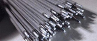
For a simple gas burner, you will need dropper needles equipped with restrictive clamps.
For a home mini-autogen you can make a fairly reliable one with a very simple design. In Fig. 2 shows a diagram of such a design.
To supply the gas mixture, it is recommended to use a needle for inflating footballs. At a distance of up to 20 mm, an incision is made using a needle file, through which a thinner needle from the dropper is inserted, previously bent at 45ºC at a distance of 15-20 mm. The structure is fixed with copper wire and carefully soldered, all gaps are sealed with varnish.
The output of the large needle is connected to the electrolyzer, i.e. designed for supplying a flammable gas mixture. Additional enrichment of it with oxygen is carried out through a small needle, which is connected to a container filled with compressed air.
The simplest container can be a ball chamber inflated by a pump or a polymer bottle into which air is forced by the same pump.
This completes the production of a simple mini-autogen. After ensuring the supply of both gas streams to the burner, they, connecting, are directed in one stream through the needle to the outside; The escaping gas is ignited and welding occurs. The temperature in the welding zone reaches 1,600ºС, which is enough to melt the edges of the metals and the filler rod.
Autogen welding algorithm
Full review of enamels for metal: tips on selection and use
Autogen welding is a rather complex procedure that must be performed in stages. Each step will be described in the list below. It is worth noting that the procedures must be performed in the exact order in which they are indicated.
- Initially, you need to open the oxygen and acetylene cylinders. Then light the arc on the welding equipment. One thing needs to be taken into account. If the welding hoses have not been connected to the cylinders for a long time, the arc of the welding machine may not ignite the first time. If this happens, then you need to wait just a couple of minutes and repeat the procedure.
- After starting the welding equipment, it is configured, which consists of achieving the required temperature (depending on the specific procedure and type of metal, the required value may vary).
- Next, using a welding machine, you need to heat the working surface of the metal product to such an extent that the heated surface turns white.
- In the case of restoration welding procedures, the use of additional welding materials is required, which undergo melting and thereby fill the empty space between the parts.
- After completing the work, the metal product with a fresh welded joint must be completely placed in a tank of cold water to cool it to room temperature.
- After the metal has cooled, using a special hammer it is necessary to beat off the slag that has arisen in the area of the welded joint.
- The last step is to check the quality of the final connection result.
Technology of metal cutting using electric arc welding
Before starting work, you must ensure that all electrical cables used are in good condition. Creating and maintaining an arc is not particularly difficult. It is ignited by tapping or striking the electrode on a metal workpiece. The amount of current on the inverter is set depending on the size of the electrodes, the thickness of the material, and the type of cut required. There are three main types of cuts.
Separation cutting
The material is installed in such a way as to ensure free flow of molten metal from the cut line. When the sheet is positioned vertically, separation cutting is carried out from top to bottom. On a horizontal surface, the cut is made from the edge of the material. If you are cutting a large sheet, you can start the process with a hole made in the middle of the workpiece.
Surface cutting
This type is used for laying grooves on the surface of the material, leveling out sagging and defects. During operation, the electrode should be positioned with an inclination of 5º-10º to the surface. During surface cutting, the movement is performed with a slight immersion into the cavity being created. If it is necessary to lay a wide groove, the electrode should perform transverse movements of a given size.
Hole cutting
This operation is performed by gradually expanding a small hole to the required size. When cutting holes, the perpendicular position of the electrode allows slight deviations towards the resulting circle.
Features of the use of different types of electrodes
For the process of cutting metal surfaces, it is possible to use various electrodes:
- metal melting;
- coal;
- non-melting tungsten.
Cutting with a consumable electrode is accompanied by the melting of metal by an electric arc from the impact zone. The work is performed with steel electrodes with a diameter of 2.5 to 6 mm, which are more refractory than when welding. A high-quality coating (manganese ore, potash) creates a small visor that covers the arc zone, which contributes to concentrated heating of the material.
Carbon electrodes are used when a certain quality and width of the resulting cut is not required. During operation, the surface of the material is positioned with a slight slope to facilitate the flow of metal. In this way, workpieces made of cast iron, steel, and non-ferrous metals can be processed. It is optimal to use an electrode with a thickness of 10 mm.
Electric arc cutting of products made of non-ferrous metals and alloy steel can be done with non-consumable tungsten electrodes, which are used much less frequently than metal or carbon ones. In this case, cutting must be carried out in a protective gas atmosphere.
In the absence of special electrodes designed for cutting material, conventional welding electrodes can be used. In this case, you should choose the appropriate diameter: for thin metal, electrodes with a diameter of 3 mm are used, for thicker ones - from 4 to 6 mm.
Operating principle of autogenous cutting
How to disassemble a gas cylinder: step-by-step instructions, precautions
The main purpose of this tool is welding and cutting metal using gas. The welding method itself is a mixture of burning gas and oxygen. The heat from the combustion of this mixture melts the metal to a liquid state, and with the help of oxygen pressure a cut is made. Also, the flame has both a reducing and an oxidizing nature. During restoration work, the use of filler materials, that is, metal rods, is required. The choice of filler rods depends on the composition of the metal and the diameter of the welded area. Accordingly, the larger the seam, the larger the metal rod.
The burning gas mixes with oxygen, and during the combustion of this mixture the metal melts.
The following metals can be cut with an autogen:
- thin steel (from 0.2 to 5 millimeters);
- non-ferrous metals (aluminium, copper, brass, stainless steel);
- tool steel (need for gradual heating and cooling);
- cast iron and various alloys with it.
The standard equipment used for autogenous cutting includes the following components: oxygen cylinder, acetylene cylinder or acetylene generator, pressure gauges, reducer, valves, hoses for supplying gas and oxygen.
Popular types of gas welding
There are different types of gas welding, which may have certain characteristic qualities. They can be used for metal workpieces with different structures, with different shapes and thicknesses. But we will look at the main methods of gas welding, which are very popular.
Left welding
The left-hand gas welding method is the most common method, which is highly popular among professional welders. It is often used by craftsmen with different qualifications.
The left-hand welding method is used to join metals with thin edges and low temperatures. It is suitable for working with low-melting and thin structures. Left and right gas welding methods are similar; they are two sides of the same coin.
When performing left gas welding, the torch must be moved from right to left. But considering the differences between the left-hand and right-hand welding methods, when carrying out the latter, the torch is passed from left to right and the filler wire is followed behind it. The heat of the flame practically does not dissipate during welding and the seam opening angle is 60-70 degrees.
Right welding
The right gas welding method is used to work with metals whose thickness is more than 3 mm and have high thermal conductivity. It is worth paying attention to the fact that during right-hand welding the seam is of better quality, this is achieved due to the protective effect of the flame.
During the right welding method, economical use of heat is observed. At the same time, the process speed is almost 20% higher. Also among the positive qualities of this welding method is the economical consumption of gases by almost 10%.
When carrying out this technology, it is recommended to use filler wire with a diameter that is almost half the thickness of the metal element being welded. But the wire cannot be thicker than 8 mm.
Welding using a through bead
This technology of gas welding and metal cutting involves the gradual movement of a flame with melting of the upper edge of a hole in a metal product and applying a layer of molten metal to the area of the lower edge of this hole.
Before starting the process, the sheets are fixed in a vertical position, leaving a gap between them half the thickness of the workpiece. The connection is made in the form of a roller that connects the metal components. It has good density; there should be no pores or any irregularities in its structure.
Welding using pools
Gas flame welding consists of the formation of more and more pools along the seam. After one is formed, one end of the filler wire is inserted into it, and here it melts. Then it moves to the area of the recovery section of the burner fire.
Meanwhile, the nozzle tip moves further along the surface of the welded joint, it moves to the next zone. Each new pool overlaps the previous one by approximately one third of the diameter of the filler wire.
Using this welding method, thin sheets are joined when it is necessary to make butt and corner seams. It is often used for welding pipe products made of low-alloy or low-carbon alloys.
Multilayer welding
This welding method is often used when carrying out critical work. It is characterized by low productivity. In addition, its implementation requires large volumes of gases, so this method is quite expensive.
It is worth noting! When carrying out multilayer welding using gas, annealing of the lower layers is observed while surfacing the upper ones. As a result, high-quality forging of each layer occurs before the formation of the main seam.
Welding with oxidizing flame and deoxidizing agent
This type of gas welding and cutting is designed specifically for working with low-carbon steel elements. During it, a flame with a sharply oxidizing character is used, which is what leads to the formation of iron oxides in the weld pool. If oxidation occurs, deoxidation is required.
Deoxidation is obtained using a special filler wire, which should contain a high content of manganese and silicon. This method has a productivity of 10% higher than other types.
Gas press welding
Gas press welding involves heating the welded products to a plastic state using an adetylene-oxygen welding torch. And after the required temperature is reached, they are compressed and welded.
There are two subtypes of this method: connection in a plastic state with seam protection and flash welding. During welding in a plastic state, axial pressure is applied to the elements that are prepared for welding and the torch is ignited. Afterwards heating is carried out, which is accompanied by compression. As soon as a thickening appears, the heating stops and the pressure is removed.
During flash welding, the parts to be welded are fixed with a gap and the torch is ignited. Afterwards, the ends of the metal elements are heated and melted. Then axial pressure is applied and the parts are welded.
Equipment configuration
Autogenous welding includes:
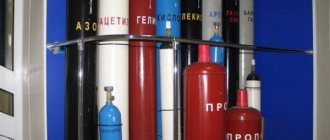
- Two cylinders: oxygen and acetylene.
- Two reducers, one for each cylinder.
- Flame arrestors, one per cylinder.
- Set of two hoses: one for oxygen, the second for acetylene.
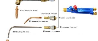
- A burner equipped with nozzles with holes of different diameters.
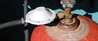
An oxygen cylinder is a metal container with a wall thickness of 6 mm, a volume of 40 liters, which holds 6000 liters of oxygen under a pressure of 150-200 atmospheres. The cylinder is seamless, which is why it can withstand such high pressure loads. In its upper part there is a valve to which the oxygen reducer is screwed. The main requirement for safe operation is to prevent oil and grease from entering the valve, especially at the junction with the gearbox. Oxygen quickly reacts with oils, and an oxidation reaction occurs, which leads to an explosion.
The acetylene cylinder has a completely different design. The thing is that compression of acetylene necessarily leads to an explosion. To prevent this from happening, it is necessary to divide this gas into small volumes. And to increase the volume itself, you need to dissolve it in acetone, which absorbs acetylene in large quantities. The absorption proportion is 1 to 360. That is, one liter of acetone absorbs 360 liters of acetylene. The mixture is broken down into small volumes due to the porous structure of the balloon filler. This material contains acetone. By the way, its quantity is equal to 16 liters, respectively, the quantity of acetylene at a pressure of 15 atmospheres will be equal to 6000 liters.
The porous material is a symbiosis of asbestos, charcoal, kieselguhr and astringent fillers. The wall thickness of the acetylene cylinder is 4-5 mm.
As in the case of an oxygen cylinder, the acetylene cylinder also has a valve, to which its own special reducer is attached. It should be noted that oils and fats in this container are not dangerous. The only thing that needs to be taken into account is to keep the acetylene cylinder in a vertical position when performing autogen welding.
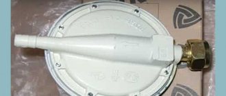
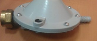
As for the reducers (acetylene and oxygen), their task is to reduce the gas pressure to the required values. Both devices have almost the same design, which is based on a spring-loaded valve. They also have two pressure gauges installed, one of which shows the pressure inside the cylinder, the second the gas pressure after the reducer, that is, on the burner.
The pressure indicators after the reducer should be as follows:
- Oxygen – 2.5-3.0 atm.
- Acetylene - 0.3-0.7 atm.
These indicators are not absolute, because gas welding is used to connect metals of different thicknesses. And the thicker the workpiece, the greater the gas pressure should be on the burner. In addition, cutting metal with an autogenous machine is also carried out at elevated pressure levels.
A flame arrestor or check valve is a device that protects against blowback. They are installed immediately after the gearboxes, and the hoses themselves are connected to it. What does reverse strike mean?
There are situations when acetylene begins to rise up the oxygen hose, reaching its reducer. If two gases mix in this place, then this is a guarantee of a big explosion. Flame suppression valves help prevent this. In addition, there are certain actions of the welder himself that ensure the safety of autogenous work. But more on that below.
Now about the hoses. What are the requirements for them?
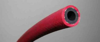
- These are rubber products with a fabric cord inside.
- The color of the oxygen hose is blue, the acetylene hose is red. Changing their places is strictly prohibited.
- They are connected to welding equipment devices only with fittings through nipples.
- Commonly used hoses have an internal diameter of 9 or 12 mm.
- Their minimum length is 8 m, maximum – 20 m.
- The hose set is a dual design of acetylene and oxygen.
The torch is the most important element of welding equipment, where the two gases are mixed and where the mixture comes out at supersonic speed. The hoses are connected to the burner using fittings. Higher up the handle there are valves with which the supply of each gas is regulated. In this case, oxygen passes through the injector, in which acetylene is drawn along with it. That is why the pressure of the acetylene reducer is set equal to atmospheric pressure or slightly higher.
Gas welding equipment
The basics of gas welding require the use of the necessary equipment. It must comply with all norms and standards that are specified in the technology of this welding process. In addition, the welder must be able to use it and know the principles of its operation.
Welding with propane, oxygen, acetylene and its substitutes involves the use of the following equipment:
- Water seal . This element protects the acetylene generator and pipes from the backdraft of fire from the burner. It must be in good working order; it must be filled with water level with the tap.
- Gas cylinder . The cylinder has a tapered thread on the hole area on which the closing valve is installed. The outside of the cylinder is painted a certain color depending on the type of gas. For acetylene, you can use a valve made of any metal except copper, with which the gas forms an explosive mixture.
- Gearbox . It causes a decrease in the pressure of the exiting gas. It can be single- or double-chamber, the latter allows you to maintain stable pressure. The gearbox can be direct or reverse acting.
- Hoses . Hoses that are used for flammable gas mixtures. They are often marked with a solid red line (this is the designation). They can be used at a pressure of 6 atm. These are first class hoses, but second class ones are used for transmitting flammable liquids (gasoline, kerosene). They have a yellow line on them. Hoses of the third class are able to withstand a pressure of 20 atm (they have a blue line).
- Burner . This equipment mixes gases, releases a mixture from a mouthpiece under the required pressure, which melts metal workpieces. Burners can be injection or non-injector. This element consists of such elements as a nipple, a mouthpiece, a tip, a mixing chamber, nuts, an injector, and a body with a handle.
- Post . This is the place for the welding process. It has a table, cabinets for storing the required elements and welding equipment. The post can have a rotating or non-rotating table top. For work in large industries, a mobile or stationary post can be used.
But still, before you start using the above elements, it is worth understanding how to cook with gas welding. This is a responsible process that requires mandatory compliance with important protective measures. Experienced welders recommend using a protective mask, a uniform made of thick fabric, and leggings.
Advice from experienced people: how to use
Table of cutting metals with a gas cutter.
First the general points:
Only with a mask! We carry out any work with any gas cutter only in a welder’s mask or special glasses. Working with an autogen is an activity with a sea of risks; safety precautions must be carried out for real and not childishly. We choose clothing and gloves with fire-resistant properties. If there are none, well: at least the minimum requirement is not to wear synthetic clothes. There must be a fire extinguisher at the workplace with all the correct expiration dates, etc.
Fire extinguishing equipment must also be placed nearby in accordance with fire safety regulations. Before work you need to stock up on: a ruler, a special pencil, a square and a tape measure; a special lighter, which is usually included with the equipment. When working, it is important to choose the right location. The torch flame should be located frontally in relation to the supply hoses
The hoses, in turn, should be positioned so that they do not interfere with you during the process. Another safety rule: gas cylinders should not be closer than 5 meters to you during operation. Ventilation should be excellent throughout cutting, preferably working outdoors. The floor in the workshop should be either concrete or earthen. If you haven't worked with your cutter for a long time, or are starting to use a new device, check the channels: they should be clean. In addition, always check the vacuum level in the chamber that is formed by oxygen. First, remove the propane hose - this must be done with the valves on both the cutter and the cylinder tightened. Then open the oxygen and gas valve on the cylinder at operating pressure. The injector is checked simply: put your finger on the gas nipple, if everything is correct, you will feel air being sucked into this nipple. Close the oxygen, all the valves and then connect the hose with flammable gas to the cutter: you can work.
Scheme of cutting metal with a cutter.
Stages of action during cutting, propane cutters:
First, an oxygen cylinder: set the operating pressure. Then a cylinder with flammable gas: we also set the working pressure. The reference point is oxygen pressure. The propane pressure should be about ten times less. If the device is three-pipe, then the difference will be five times. Slowly open the oxygen and gas valve, ignite the gas and use the valves to create the pressure of the heating flame. The manual gas cutter is ready for work, now the actual cutting of the metal with the cutter. A stream of igniting oxygen begins to flow to the combustion site. If the metal is heated sufficiently, the desired reaction will begin immediately. In this case, the oxygen supply pressure can be further increased until the metal is completely cut through. Now the autogen can be moved in the desired direction - along the line of the planned cut. The speed of movement must be determined as you go, it will depend on how the sparks and slag flow or are blown down from the burner. After cutting, carefully inspect the work area for any remaining pieces of molten metal.
God forbid you step on these - they will even burn through the thick soles of your boots. Cooling of parts is carried out either with water or naturally. After finishing cutting, you need to finish the work process, which is no less important than starting work. First we tighten the oxygen valve. The flame valves are closed next - the propane valve first, the oxygen valve next. We tighten the valves on the cylinders. We release the hoses from the gas: open and then alternately close the valves of the heating mixture on the device.
Cutting methods
There are several ways to separate material. The technology depends on the equipment used in the work process. The following types of metal cutting are distinguished:
- manual;
- waterjet;
- thermal.
Manual metal cutting
Manual cutting of metal is not highly efficient and is not used on an industrial scale. The following tools are used for manual cutting:
- scissors;
- hacksaw;
- jigsaw;
- Bulgarian.
Waterjet cutting of metal
The waterjet cutting method is based on the impact of a jet of water mixed with abrasive particles on the workpiece. The pressure of the supplied liquid is 5000 atm. The advantage of this type of metal cutting is the ability to obtain a variety of lines. Alloys of a certain grade with a small sheet thickness are processed.
Thermal cutting of metal
Hot cutting of metals is based on the absence of contact between the tool and the workpiece. The hot jet melts and separates the material in the right place.
Types of thermal cutting include:
- oxygen gas;
- laser;
- plasma.
Oxygen gas cutting
Oxy-fuel cutting consists of 2 stages:
- A jet of flame is directed to the cutting site, which comes out of the cutter. Acetylene is used as a flammable material.
- After heating, oxygen is supplied, which cuts through the softened metal surface. At the same time, oxides are removed.
During operation, the distance from the bottom point of the cutter to the surface of the product must remain constant. The quality of the cut depends on this.
Laser cutters are used for this purpose. The process is based on delivering a laser beam to a point on the surface. Thermal energy is focused. The area is heated, the material melts and then evaporates. As the beam moves, it cuts the surface.
Laser cutting of metal
Plasma
A plasmatron is used as equipment for plasma cutting. Oxygen comes out through the nozzle in it under high pressure. Its temperature is up to 20 thousand degrees. Beam width 3 mm. The surface area is heated, partially burns out, and the melt is blown out.
Mechanical metal cutting
Mechanical cutting of metal is carried out using special steel with a high degree of hardening. Due to its high hardness, the tool cuts the product.
The following types of equipment are used for cutting:
- band-saw;
- guillotine;
- disk machine.
Band saw cutting
A band saw is a blade that is fixed in special equipment. The material of the tool is the same as that of a hand-made product. There are teeth on one side. During operation of the machine engine, the pulleys rotate, due to which the belt moves continuously.
During operation there is a slight waste, because the width of the blade is 1.5 mm. It is possible to cut both sheet metal and round workpieces.
Impact cutting of metal on a guillotine
Guillotine metal cutting is used to prepare sheet steel blanks for stamping operations. The fabric to be cut is placed on a horizontal surface, fed all the way and cut with guillotine shears across the entire width in one blow.
Cutting on a disc machine
A disk is used as a working tool. There are teeth along its outer surface. There is a protective casing on top. An electric motor is used as a drive, which rotates the disk. The result is a high quality cut.
Pipe cutters are used to cut pipes using the same principle. During the work process, the workpiece is constantly rotated 360 degrees. It is possible to make cuts at different angles.
Principles of autogen miniaturization
One of the disadvantages of autogenous welding is the bulkiness of standard equipment. Currently, mini-devices are offered that allow you to carry the entire welding set manually. The bulkiness of the design is almost entirely caused by gas sources. The acetylene cylinders and generator are quite large in size and weight, which requires vehicles. A modern mini-autogen can be carried as a small hand tool, placed in a suitcase. The gas sources in such devices are small cans of compressed gas: oxygen, butane, propane, etc. The disadvantage of such mini-devices is the high price and small volume of cans, which causes problems when carrying out work in remote areas.
You can make an autogen with its own gas source and a small, simplified burner with your own hands. Such a portable device can contain a homemade hydrogen generator (based on the principle of electrolysis), which will provide power for gas welding for a sufficiently long time without replacing cylinders.
Welding autogenous generator
Acetylene gas, necessary for welding, can be purchased in white cylinders. In a big city this is not a problem; the autogenous situation is worse in small towns and rural areas - there it is quite difficult to refill with acetylene if there are no large industrial enterprises nearby. An autonomous acetylene generator, which is specially designed to produce this gas and supply it to the burner, can help out.
Inside the generator, a reaction occurs between calcium carbide and water, resulting in acetylene. In addition to welding, this gas can be used for other needs - connecting gas lamps, producing acetic acid, producing ethanol, etc. But no one does these operations either in private garages or in industrial workshops - the generator is used exclusively for welding work.
The generator structure is shown in the diagram:
The industry produces various types of generators, differing in productivity and maximum pressure of the gas produced:
- Low pressure - up to 0.01 MPa;
- Average - up to 0.15 MPa.
Autogen welding rules
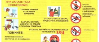
Performing welding procedures with metal products, which requires compliance with the entire technological process and safety regulations. Under no circumstances should they be neglected. Before starting the welding process, it is imperative that you familiarize yourself with the following safety precautions:
- Under no circumstances should cylinders come into contact with other flammable materials, in particular oil; if contact occurs, the cylinders will simply “fly up into the air”;
- transportation of all materials, in particular gas cylinders, is carried out only on vehicles specially prepared for this purpose;
- argon welding must be performed at a safe distance from residential buildings and other buildings and premises;
- After completing the welding work, the cylinders must be stored in a well-ventilated metal cabinet in an open area; in no case should it be placed indoors;
- During welding procedures, cylinders should be checked from time to time for gas leaks;
- During welding, there must be a fire extinguisher and other fire safety equipment near the workplace;
- Welding work should be performed away from flammable objects, products and materials.
Let's define it in terms
By non-burning flame, chemistry means a chain reaction of oxidation in which a glow is observed. So if you strictly follow the terminology, cold fire is not a flame. It is used to create very spectacular special effects and some types of fireworks. A number of esters and acids, both organic and inorganic, are capable of producing a cold flame. The most commonly used is the ethyl derivative of boric acid.
Often, cold fire also means a visual “trick” in which the combustion process as such is absent. It is usually used not for tricks, but for design purposes.
Autogen welding process
Autogenous welding without a filler rod or wire is impossible. In this case, only the metal is burned and cut into separate fragments. Mixing in the burner, acetylene and oxygen burn and are ejected from the nozzle at high speed. The gas stream reaches a temperature of more than 3000 C. It can be adjusted within certain limits by adding or reducing the proportions of the supplied gases.
First, oxygen is supplied to the burner, then acetylene or propane and the mixture is ignited. After a stable flame appears, the required temperature is set by turning the control valves. As a rule, it is difficult to measure, so the level is determined by indirect signs - the color of the flame, the sound of the gas flow, the intensity of heating of the metal.
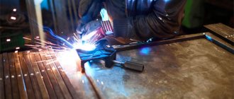
How the welding process occurs is shown in the picture:
First, the parts to be welded are installed in the desired position, then their edges are heated to white, and only then the filler rod is introduced into the burner flame. It melts and fills the seam between the parts. You can buy LNG filler rod (I, II, III or IV) and other modifications, as well as welding wire for autogenous welding at any welding equipment store.
Autogen welding is a rather complex process in its technique, and you should not undertake welding of critical parts without preparation. It is best to practice on cuttings of pipes, channels and other profile products in order to gain experience and master practical working techniques.
Manufacturing
The manufacturing process occurs in several sequential stages:
- A gas supply needle is made, which acts as the tip of a gas cutter. On the needle used to inflate balls, a small incision is made using a needle file at a distance of about 2 cm from the end.
- An air (oxygen) supply needle is made. To do this, you need to take the needle from the dropper, file off the sharp tip with a sharpener, and bend it at 45 degrees at the same distance (about 2 cm). After this, the curved needle is inserted into the hole that was previously made in the large one.
- If necessary, the protruding ends of the resulting structure of two needles are leveled with a file or a sharpening stone.
- To seal the joint and fix the connection of the needles to each other, it is necessary to wrap it with copper wire, prepared in advance and cleaned of oxide. After this, the winding is coated with flux used for soldering and carefully but carefully soldered with tin.
- Dropper tubes are attached to the rear ends of the needles. In this case, the clamps are not removed from them, since they will be used to regulate the size of the flame.
- A container is made for oxygen (or ordinary air under pressure). To do this, a hole is cut in the bottom of the prepared plastic bottle for a nipple from a car camera, which is installed there using glue and a special nut. This design will allow you to pump compressed air into the bottle using an ordinary car pump. As an alternative and more convenient option, an aquarium compressor or even an electric car pump can be used.
- A hole is made in the cap of the PVC bottle to install a dropper in it, which is pre-cut to the so-called “skirt”. The connection between the cap and the dropper must also be carefully sealed using thermal adhesive.
- The resulting structure is connected using a dropper tube to the hole of a small needle. Thus, the part of the cutter through which the compressed air will have to flow is almost complete.
- A second line is made, intended for the passage of gas from the cylinder, which is used to refill lighters. It is necessary to make a hole in the plastic lid of the can, the diameter of which must coincide with the dropper tube. The tube is then inserted into the resulting hole. A special nozzle is installed at its end, which is usually supplied with the cylinder. The connection must be as tight, airtight and durable as possible. After this, the tube with the installed nozzle is fixed in the plastic cover so that in the closed position it puts pressure on the nipple of the balloon.
Your own gas cutter for metal is ready.
Practical recommendations for cutting
Cutting metal with a gas cutter
Using an insert cutter turns a gas torch into a tool that cuts metal along straight and curved contours, makes holes of large and small diameters, cuts pipes and metal rods. The insert cutter is the most convenient device for beveling the edges of products that must be joined end-to-end. Before cutting begins, the metal is heated by an annular flame created by the holes of a special mouthpiece located in a circle. After heating the metal, the lever turns on the oxygen supply through the central hole in the mouthpiece, which burns the metal as the cutter moves along the cutting line. During both heating and cutting, the edge of the flame core should be approximately 3 mm above the metal.
To improve cutting accuracy, the cutting line should be marked with special chalk that does not collapse when heated. Marking the cutting line can also be done with a center punch, placing the marks it leaves at a distance of approximately 6 mm from each other. A corner or a special jig should be used as a guide to move the insert cutter along the cutting line.
Just like welding, different insert torches are used to cut metals of varying thicknesses. There is a table to help you select the recommended torch for the job, as well as the appropriate oxygen and acetylene pressures (different from the pressures recommended for welding).
Rice. 123. Insert cutter device
: 1 - mouthpiece; 2 — insert cutter; 3 — oxygen supply lever; 4 — oxygen supply valve; 5 — cutter handle; 6 — holes for heating the metal; 7 - hole for cutting metal
Rice.
124. Flame adjustment
: 1 — oxygen supply valve; 2 — oxygen supply valve to the burner; 3 — acetylene supply valve to the burner; 4 - normal cutting flame
Insert cutter device
(Fig. 123). An insert cutter is screwed to the welding torch barrels, which delivers a mixture of oxygen and acetylene through one tube into small holes in the mouthpiece located in a circle. This mixture is used to heat the metal before cutting. For cutting metal, a separate tube is provided, which opens and closes with a special lever and supplies oxygen from a cylinder to a large central hole in the mouthpiece. The oxygen supply valve is used to control the supply of oxygen to the preheat port. Oxygen is supplied to the central hole under pressure, which is maintained in the supply hose.
Flame adjustment
(Fig. 124). Prepare the installation in the same way as for welding work and attach the insert cutter to the welding torch barrels. Set the operating pressure of oxygen and acetylene to the recommended values for the given mouthpiece size. To ignite the torch, open the oxygen supply valve fully and the acetylene supply valve approximately halfway and light the gas by bringing the igniter to the mouthpiece. Set the flame to normal by rotating the oxygen valve on the cutter insert. Press the oxygen supply lever for a second and check the resulting flame (if necessary, make it normal).
Oxygen straight line cutting
Rice. 125. Oxygen straight line cutting
: 1 - clamp; 2 - cutting line; 3 - conductor; 4 — oxygen supply lever
Using a homemade guide
(Fig. 125). Draw a cutting line with a special chalk or center punch and place the workpiece on a table covered with metal so that the distance from it to the edge of the table is at least 100 mm. Using two clamps, secure a piece of angle iron so that there is a distance of approximately 6 mm between it and the cutting line and it can be used as a guide. Holding the side of the torch against the corner, make two or three slow passes along this line. To ensure stability, rest your forearm on the table. Heat the metal to a bright red color at the beginning of the cut, then open the oxygen supply completely with the lever and begin to move the cutter flame evenly along the marked line, using the corner as a guide.
Read also: Rectangular pipe assortment
Using Oxygen Cutting to Bevel Edges
Rice. 126.
What are gas cutters and what types do they come in?
Gas cutters are designed for cutting rolled metal and dismantling metal structures. The principle of operation of a cutter for cutting metal is quite simple - gas burns at the end of the torch, creating a high temperature zone exceeding the melting point of the metal. Gas is supplied to the burner through a hose from a portable cylinder built into the handle or from an external cylinder through a hose. Air oxygen can be used to oxidize flammable gas; in other designs of oxygen cutters, gas is supplied from a separate cylinder through a separate hose.
There are many types of gas cutters and torches. Existing types of cutters are classified according to the following criteria:
- by type of cutting; superficial;
- dividing;
- manual;
- propane;
- injection;
- low;
- multi-nozzle;
- small - up to 100 mm;
Mini gas cutter
In addition, there are ultra-portable pocket-type mini gas cutters, the power of which allows, however, to cut several millimeters of steel or copper sheet. This gas cutter is ignited by a match or by a built-in piezoelectric element.
An injection cutter for manual oxygen cutting not only does not fit in a pocket, but also requires an impressive cart to transport its cylinders. Stationary cutters for cutting sheet metal are complex automated industrial installations with an area of tens of square meters; gas is supplied to them through a stationary gas pipeline from large gas tanks.
Disadvantages of processing
Low carbon steel is most suitable for gas cutting, but medium and high carbon steel is not a very suitable material for cutting. Due to the high carbon content, the ignition temperature increases and the melting point decreases. And this condition complicates the cutting process.
It is difficult to cut metal using a gas mixture if it has low thermal conductivity. Therefore, these types of material are not suitable for processing.
Safety rules when gas cutting metal
Gas cutting of metal should only be carried out by a qualified and experienced professional.
It is important to observe all the key factors of proper processing: oxygen pressure and speed of the procedure. It is necessary to take into account the thickness of the product and the diameter of the cutter nozzle
If the rate of oxidation and metal cutting do not match each other, then the result will be poor-quality processing.
Oxygen cutting involves the use of explosive substances. If safety rules are not followed, there is a high probability of an explosion of the gas-air mixture; it is necessary to monitor the condition of the gas equipment. To protect against burns, you must use personal protective equipment.
A significant disadvantage is the possibility of metal deformation and low cutting accuracy.
Related video: Cutting metal with a cutter
Useful articles
Plasma cutting of metal - features and advantages of work
List of metal cutting companies in Rostov-on-Don
Making your own laser for cutting metal - instructions and recommendations
Refilling the tank
Refueling should only be done upside down. The lighter must be taken in your hand so that it can be easily held, preferably with an emphasis on some hard surface. First, shake the gas canister several times.
Insert the nozzle of a can with a suitable nozzle tightly into the filling valve and press it onto the filling rod. If liquid gas begins to fill the tank, the lighter body will quickly cool. Do not prime for more than five seconds. If this is not enough, repeat the procedure after a while. The release of excess gas will indicate that the tank is completely filled.
Gas cutter for metal: varieties
Gas cutters are divided into types according to various parameters. The main ones are the following:
by type of flammable gas:
- acetylene;
- methane;
- propane-butane, etc.
based on the principle of mixing oxygen with flammable gases:
non-injector; injection;
for main purpose:
for cutting under water; for cutting thick material; for cutting holes; universal;
by type of cutting:
spear; oxygen-flux; superficial; dividing.
Currently, the most popular gas cutters are the universal type. They are distinguished by the following positive qualities:
- carry out cutting in any direction with material thickness, mm: 3…300;
- quite easy to use;
- very stable;
- withstands reverse impacts well;
- have a small mass.
Propane
A propane gas cutter can cut metal sheets up to 300 mm thick. The equipment has a whole set of technical characteristics that contribute to its long-term operation. Many parts are easily replaceable and, if necessary, can be replaced directly during the work process (without leaving the work site). In most cases, replacement with analogues is possible. In addition, propane has a relatively low cost. This makes using propane cutters even more beneficial.
As an example, consider the Mayak 2-01 and RS-3P propane burners.
"Mayak 2-01" is used for manual separation and oxygen cutting of low-alloy and carbon steels.
Its technical characteristics:
- thickness of cut steel, mm: 3…100;
- flammable gas: propane;
- sleeve diameter, mm: 9/9;
- length, mm: 580;
- weight, kg: 1.3.
Propane mouthpieces supplied:
- external No. 1;
- internal No. 1 (for cutting metal thickness, mm: 8...15) - installed on the cutter;
- spare parts included:
- No. 2 (15...30 mm);
- No. 3 (30...50 mm);
- No. 4 (50...100 mm).
"RS-3P" is an oxygen-gas injection gadget designed for manual cutting of low-alloy and carbon steels.
Its technical characteristics:
- thickness of cut steel, mm: ≤ 200;
- gas used: propane / methane;
- length, mm: 500;
- climatic version: UHL 1 and T 1 according to GOST 15150;
- operating temperature, °C:
- when working on acetylene: + 45...minus 40;
- when working on propane-butane: +45ºС…minus 15;
weight, kg: 1.05.
Acetylenic
Acetylene cutters are designed for manual separation, oxygen-acetylene cutting of carbon and low-alloy steels. Classic ones are injection-type cutters:
The mixing of gases in them occurs in the injection chamber, which is located near the handle.
The thickness of the metal cut by this equipment depends on the number of the mouthpieces on the cutter:
- type P1 (for example, “P1-01”) are equipped with mouthpieces that allow cutting metal up to 50 mm thick;
- type P2 (“P2-01”, “Mayak-1-01”) are equipped with mouthpieces that provide cutting of metal up to 200 mm thick.
Portable cutting torch
Many had the opportunity to observe the hard work of gas welders, transporting large and heavy cylinders with flammable gas and oxygen to the workplace on various carts. To create mobility, the cutter is connected to the cylinders via long hoses. It is inconvenient and quite difficult to work with such a device. Moreover, it is these long hoses that create the greatest inconvenience.
It’s a completely different matter if you have a small, portable, injection-type gas cutter at your disposal. It is moved from place to place by 1 person. If necessary, he can raise it to a considerable height. This gadget includes:
- gas welding torch or cutter;
- short hoses up to 5 meters long;
- 2 oxygen cylinders with a capacity of 5 liters;
- 1 propane cylinder, the capacity of which can be: 2, 3 or 5 liters.
Oxygen and flammable gas cylinder.
Gas cutters that are mounted directly on the cylinder are widespread. They, heating the surface to T = 1300 °C, are often used for various household purposes (for example, for welding metals with low melting points). The heating temperature they create is sufficient to soften the following metals:
For comfortable operation, gas cutters are equipped with a can mount and are equipped with piezo ignition. These gadgets are autonomous and compact. This makes them convenient to use both outdoors and in the garage. The devices are very versatile:
- They are convenient for lighting a fire outdoors in cloudy weather;
- they are used to warm up a frozen padlock at the gate of a country house or cottage and in many other cases.
Injectorless gas cutter model, portable gas cutter for metal
Advantages and disadvantages of electric arc cutting
Welding cutting, like any technology, has its advantages and disadvantages, taking into account which will allow you to get the job done quickly and achieve the expected result. The main disadvantages of the method include:
- low productivity, which is due to low speed;
- poor quality of the cut obtained as a result of hardening of leaks from the back side of the workpiece.
The listed disadvantages make the method inapplicable in conditions where it is necessary to maintain precise markings when cutting metal.
The main advantages that distinguish this method:
- no need to purchase special expensive equipment and tools;
- no special requirements for environmental conditions;
- quick training in operating techniques and mastering equipment;
- ability to work with direct or alternating current.
Many organizations in the construction, repair, and automotive industries, as well as home craftsmen, successfully use electric welding cutting, since this method is intended for simple, inexpensive cutting of various metal surfaces.
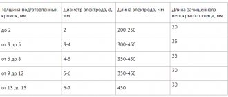
Welding current
What about welding current? As you, I hope, have already understood, the higher the welding current, the more energy is transferred to the welding zone, the stronger and deeper the metal melts and the “thicker” products you can join. And to transmit a greater current, a thicker conductor is needed. Accordingly, we can reach a direct relationship: metal thickness - electrode thickness - current strength. Welding machines are often marked with signs corresponding to the thickness of the electrode and the welding current. I recommend that you do not take such tables as dogma - they are just a starting point to guide you. For household use, a current of up to 160A is sufficient, which allows you to use a 4 mm electrode. In my memory, I very rarely used this diameter of electrodes. Basically it is 2 and 3 mm. There is also a diameter of 2.5 mm for electrodes of the UONI-13/45, 15/55, NIAT-3M brands (types for carbon steels). Approximately the strength of the welding current can be determined by the formula: I=Kdel. Where K is an experimental coefficient equal to 40-60 mm for electrodes made of low-carbon steel and 35-40 mm for electrodes with a rod made of high-alloy steel, and del is the diameter of your electrode.