The welding inverter type resanta SAI 190, like all others, has significant advantages compared to a conventional welding machine. Thanks to the mobility and small weight of the resant, ordinary welding units have been forced out of the market. There are cases of inverter failure, and for this you need to know the principle of operation, structural diagram and malfunctions of the Resanta Sai 190.
Electrical circuit of the resanta welding machine
DIAGRAM OF WELDING INVERTER AND DESCRIPTION OF OPERATING PRINCIPLE
USING THE EXAMPLE OF WELDING MACHINE RESANTA SAI 140
We were able to find two basic circuits for the Resanta SAI 140 welding inverter. Their controls are very similar, but technologically they are quite different.
The first version of the schematic diagram of the Resanta 140 welding inverter is made using a control transformer, and the second version is made using optodrivers for power transistors. There are also differences in the control power supply. The first is self-powered, and the second uses a separate power source. Since the first one is similar to what I have, i.e. a control transformer is used, then we’ll start with it.
So, we apply power and see what happens. The voltage of 220 volts passes through the filter at C3 and L... Sorry, for some reason in the diagram THIS is indicated by transformer T1 and reaches capacitors C1 and C2. The capacity of these capacitors for a frequency of 50 Hz is too small, but they release static onto the housing perfectly, and it is for this reason that it is extremely advisable for the transformer to use grounding, only with a real one, and not have a socket in which there is a grounding terminal that is not connected anywhere.
At the top there is point No. 1, just on the left terminal of the RTS thermistor, and on the right terminal of resistor R2 there is point No. 2. These number points go to the contacts of relay RL1, which is not turned on now - we have just applied the supply voltage and for now capacitors C4 and C5 are charging through the thermistor and R2, of course passing through the diode bridge.
As the capacitors charge, the +300VDC voltage begins to increase and current begins to flow through resistor R21, charging C18 and C19. Here you should pay attention to the LM324 operational amplifier used, which already starts working at a supply voltage of +3 volts, i.e. When the voltage at the upper terminal of C19 reaches three volts, the operational amplifier begins to perform its functions. Now we look very carefully, not forgetting to switch the brain to the ON state.
Resistance R21 is 20 times less than the sum of resistances R22 and R23, and capacitance C19 is 4700 times greater than capacitance C20, therefore the voltage at the upper terminal of C20 will be greater than the voltage at the upper terminal by 0.6 volts - the drop voltage across diode D24. This, in turn, will definitely put the comparator on U2A into a state where its output will have a voltage close to the supply voltage, therefore LED2 will light up, and transistor Q8 will be open, and while it is open, the voltage at the U2D output will be close to zero. This, in turn, simulates exceeding the operating threshold of the comparator of the U1A controller, and if it were working, its output would be zero. But it does not work because the transistor Q7 that supplies power to it is still closed. Meanwhile, capacitor C19 continues to charge and the voltage across it increases. As soon as it exceeds 5 volts, the reference voltage driver on D25 comes into play - it prevents the voltage at pin 2 of U2A and pin 5 of U2B from rising above 4.7 volts. At pin 3 of U2A the voltage is still greater than at pin 2 and the voltage at the comparator output continues to be kept close to the supply voltage. The voltage at pin 6 continues to increase because this pin is connected to the voltage divider across resistors R49 and R50. And while the voltage at the 6th pin is less than the reference 4.7 volts, the comparator U2B keeps a voltage at its output close to the supply voltage, and this keeps transistor Q7 in the closed state.
As soon as the voltage at the upper terminal of C19 becomes equal to 12 volts, a voltage equal to 4.9 volts is generated on the divider, and this is greater than the reference voltage of 4.7 volts and the comparator U2B generates a voltage close to zero at its output, transistor Q7 opens and supplies power to the controller UC3845. The controller begins to issue control pulses and the power transistors begin to open. But they do this for a very short period of time, since the controller generates a simulation of exceeding the output current by the still open transistor Q8. Voltage appears on the control power winding and now the entire control can consume much more current. This voltage is stabilized by the switching stabilizer U1 and here one problem becomes clear - if initially the voltage from the left pin of R21 goes to the entire circuit at once, then we will never start up - the fan consumes too much and the voltage will not increase at the upper pin of C19. The author of the diagram took this point into account and made an amendment to the diagram - only after the voltage stabilizer for control starts operating, power is supplied to the fan and to the soft start relay and to the upper terminal of the control transformer. As for the mark on the LED1 backlight, this is excluded - voltage will not appear there until the UC3845 starts, and it will not start because there is no power to it. Meanwhile, capacitor C13 is charged to a voltage exceeding 5 volts and the zener diode D19 passes current to the base of Q6, which opens and turns on relay RL1, which bypasses the current-limiting thermistor and resistor R2 with its contacts.
Meanwhile, voltage appears at the inverter output and, after passing the current limiter, the ISO1 LED lights up. The optocoupler transistor opens and sharply reduces the voltage at pin 3 of the comparator U2A. Since the voltage at the inverting input is now greater than at the non-inverting input, the comparator switches to a state where its output is zero. LED2 goes out, and transistor Q8 closes, unlocking the regulating voltage amplifier for the UC3845 controller and the controller is already generating pulses of maximum duration, since there is no load yet and there is no need to limit the current. During work, i.e. When welding, current adjustment is made by comparing the voltage from the current transformer with the control voltage, which is generated by the U2D amplifier. There is a separate video and article about the operating principle of the UC3845, links in the description.
Therefore, we will consider only the remaining nodes. The power transistors are controlled using a control transformer, the secondary windings of which go through Schottky diodes to the gates of the power transistors in the presence of a control pulse. As soon as the control pulse stops, the residual magnetic energy is reset D15...D17, and the power transistors are closed using transistors Q3 and Q5, and this happens through capacitors C 9 and C 10. These capacitors allow you to get more energy to close the transistors and this happens exactly at the moment end of the control pulse. In the presence of a control pulse, both transistors of the welding inverter open and a current flows through the primary winding, which creates a magnetic field that induces voltage on the secondary winding. When the control pulse disappears, the transistors close, and the unspent magnetic energy is dumped onto the primary power buses through diodes D2 and D3, thereby completely demagnetizing the magnetic circuit of the transformer and preparing it for the next cycle of energy transfer to the secondary winding.
The services of this welding inverter include protection against overheating and sticking of the electrode, performed on one control element - optocoupler ISO1. While the LED of this optocoupler is lit, the open transistor of the optocoupler forms almost zero at pin 3 of U2A. As soon as the electrode touches the workpiece being welded, the voltage is supplied to the LED for some time due to the energy accumulated in the capacitor C34. This time is the time for ignition of the arc and if the arc does not ignite, i.e. the electrode is stuck, the optocoupler LED goes out, thereby closing the optocoupler transistor. At pin 3 of the comparator U2A, almost a supply voltage appears and the comparator lights up LED2 and opens transistor Q3, which smothers the control voltage to ground and the controller produces only very short control pulses that do not allow the power stage to be overloaded - the work is almost a short circuit and the only resistance The secondary voltage is the reactance L1, the inductance of which is chosen so that it affects only the shortest pulses. As soon as the electrode is torn away from the workpiece, the voltage at the inverter output appears again and the optocoupler LED lights up again. Comparator U2A extinguishes LED2 and closes transistor Q8, thereby returning the UC3845 controller to normal operation. If overheating occurs, then the self-recovering thermal fuse KT is triggered, which breaks the power supply circuit of the optocoupler and the LED goes out and the processes are repeated - the LED2 LED is on, and at the output of the welding inverter there are very short pulses that do not allow welding work to be carried out and this state is maintained until the radiator cools down and The thermal fuse will not turn on.
Inverter type welder
Old transformer modifications of the welding machine have a very low price, high repairability, but have significant disadvantages: dimensions, significant weight and dependence on the mains voltage. The output current of the electronic meter is limited by electricity consumption to 4.5 kW. For welding work when using thick metals, current consumption increases, and this process places a significant load on old power lines, which also contain strands (after all, in the former CIS countries they are rarely replaced with new ones).
They have been replaced by inverter-type welding machines, the operating features of which are significantly different.
Features of operation
The scope of application is varied, ranging from households to enterprises. The main task is to ensure stable combustion and maintenance of the welding arc when performing welding work, thanks to the use of high frequency current. The operation of the welding inverter is based on the principles:
- Conversion of alternating input voltage 220 V to direct (direct current is converted into high-frequency alternating current of a non-sinusoidal nature).
- Subsequent rectification of the high-frequency current (frequency is maintained).
Thanks to these principles, there is a significant reduction in the weight and dimensions of the inverter, which makes it possible to additionally integrate cooling.
Operating principle and main characteristics
To troubleshoot inverter welding machines, you need to familiarize yourself with its block diagram. It consists of the following elements:
- Rectifier.
- Inverter.
- Transformer.
- High frequency rectifier.
- Control and stabilization circuit (driver and control board).
- Welding current regulator.
Thanks to this device, weight and dimensions are reduced. The use of a pulse transformer allows you to obtain powerful currents in the secondary winding. Consequently, the welding inverter is an ordinary switching power supply, like in a computer, but with quite a lot of power. As the frequency increases, the mass and dimensions of the transformer decrease (inversely proportional). To obtain high frequencies, powerful key transistors are used.
Switching occurs with a frequency from 30 to 100 kHz (depending on the SAIPA model). Transistors only operate from direct voltage (U), converting it into high frequency current. The result is a direct current from the rectifier (rectification of the mains voltage 50 Hz). In addition, the rectifier includes a capacitor filter. When current is passed through the diode bridge, the negative amplitudes of the alternating U are cut off (the diode passes current only in one direction). Positive amplitudes are not constant and a constant U is obtained with noticeable ripples, which must be smoothed out using a large capacitor.
As a result of the transformations, a DC voltage of over 220 V appears at the filter output. The diode bridge and filter form the inverter power supply. The transistors are connected to a step-down pulse high-frequency transformer, the operating frequencies of which range from 30 to 100 kHz (30000.100000 Hz), exceeding the mains frequency by 600 or 2000 times. As a result, there is a noticeable reduction in weight and dimensions.
The most common models are the resanta SAI 220 (220a, 220k), as well as the 190 (190a) model. Welding inverters have similar characteristics, differing in welding current:
- Mains voltage ranges: 145.270 V.
- Maximum current: up to 35 A.
- No-load voltage: 75.85 V.
- Arc forming voltage: 22.30 V.
- Welding current ranges: 5.270 A.
- Load duration (maximum current): 4.8 min.
- Maximum diameter (d) of electrode: 5 mm.
- Weight: about 5 kg.
Technical parameters of Resanta SAI-190
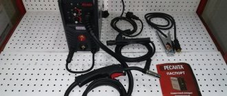
The Resanta SAI-190 kit includes two power cables 2 and 1.5 meters long, an electrical holder, and a grounding terminal. Main technical parameters of the inverter:
| Characteristics | Values | Unit measurements |
| Welding arc voltage | 27 | V |
| Total weight | 2700 | G |
| Inverter dimensions | 0.15x0.3x0.37 | m |
| Maximum current during welding | 25 | A |
| Metal case protection | IP21 | — |
| Required mains voltage | 220 | V |
| Allowable electrode diameter | 5 | mm |
| Power level | 5 | kW |
| Idling | 80 | V |
| Cooling method | air | — |
A more advanced model, Resanta SAI-190 Prof., is in great demand among professional welders. The key difference is the presence of the ARC FORCE function, which makes it possible to control the current during the welding process from 10 to 190 A. The mains voltage is acceptable in the range from 100 to 260 V. The maximum current has been increased to 33 A.
Scheme and repair
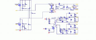
If you don’t want to send the welder in for repairs and want to figure it out yourself (after all, the diagram is not that complicated), then you need to find and study the diagram and faults of the RESANTA SAI 190. If you have experience, then you don’t have to use the diagram at all, which is only needed for convenience and quick search malfunctions. To illustrate the example, a diagram of an inverter-type welder RESANTA SAI 220 (190) is shown, and the main radio elements that often fail are noted.
Scheme 1 - Electrical diagram of the welding inverter Resant SAI 220.
To repair the device, you need to understand typical faults and how to eliminate them.
Typical faults
Sometimes an inverter-type welding machine malfunctions. The causes and consequences can be varied. If possible, you should take it in for repairs. However, many will want to do it themselves. Thanks to this solution to the issue, you can increase your knowledge in the field of electrical engineering, because there are a lot of electrical devices and you can significantly save on their repair. Faults should be classified into simple and complex. Simple ones include:
- Overheating due to dust.
- Broken wires.
- Loss of power (due to wet housing).
- Punching the mass onto the body.
- Bad contacts.
- Electrode sticking.
Any electrical device does not like dust, since it impedes the transfer of heat and is a conductor of current (possibly a short circuit). Even with high-quality cleaning of the room, there will still be dust. Regular maintenance can not only extend the life of the devices, but also protect you from many financial and repair problems.
The main advantages and disadvantages of the inventor Resanta Sai-190
The Resanta model belongs to a number of semi-industrial devices, since it can be used at home and on an industrial scale with equal efficiency. The device is considered quite mobile, as it is light in weight and relatively small in size. Excellent performance, low consumption of electrodes and electricity, simple regulation are the main advantages of the inverter. The device allows you to weld different types of metals.
Technical parameters of SAI-190 in comparison with other Resanta welding machines
Many welders note a significant drawback - the cable is too short, which limits the possibilities for welding work. In addition, the electric device does not tolerate humidity and cold, which makes it necessary to take into account climatic conditions. If this recommendation is ignored, the welding inverter will quickly fail. What is also important: the cost of the device exceeds most analogues with similar characteristics.
Despite certain disadvantages, the modern inverter is in great demand. The device is made in China, but has good repairability. Most breakdowns are associated with non-compliance with operating rules. To ensure high-quality and stable work, it is recommended to adhere to all recommendations specified in the instructions. You should focus on caring for equipment - removing dust and accumulated dirt.
Diagrams of popular Resanta welding inverters
Reading time: 9 minutes
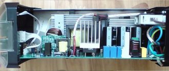
Any electrical device consists of many components that ensure its stable operation. And the welding machine was no exception. If you disassemble the inverter and carefully examine it, it will become clear that there are a lot of electrical components and it is simply impossible to understand them at first glance.
In such situations, the circuit diagram of the inverter apparatus comes to the rescue. In this article we will tell you what the circuit diagram of a welding inverter is. You will also learn what are the circuit diagrams of four popular inverters from Resanta: SAI 220, SAI 250PROF, SAI 190 and SAI 160.
Why do you need a diagram?
In a general sense, a diagram is a way of simplifying the representation of an electronic device. When talking about welding machines, the term “circuit diagram” is usually used. The circuit diagram shows the location and interconnection of all the electronic components of the inverter. You may need the diagrams to repair or assemble your device at home.
The electrical circuit of an inverter welding machine contains complete information not only about the relationship of all components, but also the names of these same components. Using the circuit, you can find any component in the inverter itself and, for example, replace it with a new one. Simply put, a diagram is a list of all the electronic components of a welding inverter and a depiction of their interconnection.
Description of devices and diagrams
Next, we will talk about four popular Chinese welding inverters from the Resanta brand. It is Chinese, and not Latvian, as many people confuse.
Resanta SAI 220
The Resanta SAI 220 machine is one of the most popular welding inverters from the entire SAI line. At the same time, one of the most expensive among its “brothers”. The only more expensive model is the SAI 250PROF, which we will talk about later.
The Resanta SAI220 model is designed for welding using coated electrodes. The device is not suitable for professional use, only for domestic use. However, this welding inverter successfully copes with simple repairs in the country house or garage. It is also suitable for learning the basics of welding.
Now about the characteristics. Resanta SAI 220 produces up to 220 Amps of welding current, which is more than enough for a beginner or a practicing welder. By the way, looking at the name of the devices in the SAI line, it’s easy to guess what current strength a particular model has