An operational amplifier (op-amp) has a complex internal structure, which we will not delve into, focusing on practical applications. The graphical symbol of an op-amp does not refer to its appearance (especially since it can be available in different packages), but to its operating principle:
Op amp graphic symbol. We (In) - input, Wy (Out) - output
This symbol is very simplified. If we wanted to place all the necessary strapping and correction details on it, we would have to draw more contacts. But most often this is enough.
Description of the LM358 chip
Confirmation of the high popularity of the microcircuit is its performance characteristics , which allow the creation of many different devices. The main indicative characteristics of the component include the following.
Acceptable operating parameters: the microcircuit provides single and bipolar power supply, a wide range of supply voltages from 3 to 32 V, an acceptable slew rate of the output signal equal to only 0.6 V/μs. Also, the chip consumes only 0.7 mA, and the offset voltage is only 0.2 mV.
Handymen will be interested in the article about the trailer connection diagram and the pinout of the towbar socket.
Working conditions
VCC = ±15 V, TA = 25°C
| Parameter | Conditions | TYP | Unit change | |
| S.R. | Slew rate at unity gain | RL = 1 MΩ, CL = 30 pF, VI = ±10 V (see Fig. 3) | 0.3 | V/μs |
| B1 | Bandwidth at unity gain | RL = 1 MΩ, CL = 20 pF (see Fig. 3) | 0.7 | MHz |
| Vn | Equivalent noise voltage referred to input | RS = 100 Ohm, VI = 0 V, f = 1 kHz (see Fig. 4) | 40 | nV/vHz |
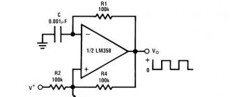
Unity gain amplifier
Circuit for checking noise
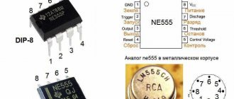
Description of pins
The microcircuit is implemented in standard DIP, SO packages and has 8 pins for connecting to power circuits and generating signals. Two of them (4, are used as bipolar and unipolar power supply terminals, depending on the type of source or design of the finished device. Microcircuit inputs 2, 3 and 5, 6. Outputs 1 and 7.
The operational amplifier circuit has 2 cells with a standard pin topology and without correction circuits. Therefore, to implement more complex and technologically advanced devices, it will be necessary to provide additional signal conversion circuits.
The microcircuit is popular and is used in household appliances operated under normal conditions, and in special ones with high or low ambient temperatures, high humidity and other unfavorable factors. For this purpose, the integral element is available in various housings.
Purpose
Why do you need a comparator and how to use it without an amplifier?
In most cases, this device is used in simple computer circuits where it is necessary to compare incoming voltage signals. This can be a charger for a laptop or phone, a scale (mass meter), an AVR mains voltage sensor, a timer (composer type lm 358, microcontroller, etc. It is also used by various integrated circuits to control input pulses, providing communication between the signal source and its destination center. The most popular example is the comparator trigger (regulator) Shimmer. It operates in multi-channel mode, accordingly, it can compare a large number of signals. In particular, this trigger is used to restore a digital signal that distorts the connection depending on voltage level and distance of the power source.
This is an analogue of a standard comparator, just with more advanced functionality, which provides measurement of several incoming signals.
There is also a roughness comparator. This is a device that helps to visually determine the condition of a surface that has already been treated. The use of this device is justified by the need to determine the tolerances of previously processed surfaces.
Microcircuit analogues
Being average in terms of parameters, the LM358 operational amplifier has similar technical characteristics . The component without a letter can be replaced with OP295, OPA2237, TA75358P, UPC358C, NE532, OP04, OP221, OP290. And to replace LM358D you will need to use KIA358F, NE532D, TA75358CF, UPC358G. The integrated circuit is produced in a series with other components that differ only in the temperature range, designed to operate in harsh conditions.
There are operational amplifiers with a maximum temperature of up to 125 degrees and a minimum of up to 55. Because of this, the cost of the device varies greatly in different stores.
- Audio amplifier circuit using one transistor
The series of microcircuits includes LM138, LM258, LM458. When selecting alternative analog elements for use in devices, it is important to consider the operating temperature range . For example, if the LM358 with a limit of 0 to 70 degrees is not enough, then the more rugged LM2409 can be used. Also, quite often, for the manufacture of various devices, not 2 cells are required, but 1, especially if the space in the body of the finished product is limited. One of the most suitable for use in the design of small devices are op-amps LM321, LMV321, which also have analogues AD8541, OP191, OPA337.
Features of inclusion
There are many connection diagrams for the LM358 operational amplifier, depending on the necessary requirements and the functions performed that will be presented to them during operation:
- non-inverting amplifier;
- current-voltage converter;
- voltage-current converter;
- differential amplifier with proportional gain without adjustment;
- differential amplifier with integrated gain control circuit;
- current control circuit;
- voltage-frequency converter.
Characteristics table
| Parameter | LM358, LM358N |
| Power, volts | 3-32V |
| Bipolar nutrition | ±1.5V to ±16V |
| Current consumption | 0.7mA |
| Input offset voltage | 3mV |
| Input compensation offset current | 2nA |
| Input current offset | 20nA |
| Output slew rate | 0.3 V/ms |
| Output current | 30 - 40mA |
| Maximum frequency | 0.7 to 1.1 MHz |
| Differential Gain | 100dB |
| Working temperature | 0° to 70° |
Microcircuits from different manufacturers may have different parameters, but everything is within normal limits. The only thing that can differ greatly is the maximum frequency: for some it is 0.7 MHz, for others it is up to 1.1 MHz. There are a lot of options for using ICs; there are about 20 of them in the documentation alone. Radio amateurs have expanded this number to more than 70 schemes.
We recommend reading: How to make a tube headphone amplifier with your own hands
Typical functionality from the datasheet in Russian:
- comparators;
- active RC filters;
- LED driver;
- DC summing amplifier;
- pulse and pulsation generator;
- low voltage peak voltage detector;
- bandpass active filter;
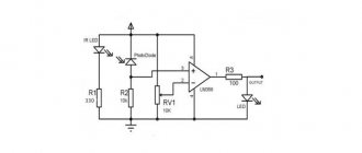
- for amplification from a photodiode;
- inverting and non-inverting amplifier;
- balanced amplifier;
- current stabilizer;
- AC inverting amplifier;
- DC differential amplifier;
- bridge current amplifier.
Popular circuits for lm358
There are various devices assembled on the LM358 N that perform specific functions. In this case, these can be all kinds of amplifiers, both UMZCH and in intermediate circuits for measuring various signals, an LM358 thermocouple amplifier, comparing circuits, analog-to-digital converters, etc.
Non-inverting amplifier and voltage reference
These are the most popular types of wiring diagrams used in many devices to perform various functions. In a non-inverting amplifier circuit, the output voltage will be equal to the product of the input voltage and the proportional gain formed by the ratio of two resistances included in the inverting circuit.
The voltage reference circuit is highly popular due to its high practical performance and stability in various modes. The circuit perfectly maintains the required output voltage level. It has been used to build reliable and high-quality power supplies, analog signal converters, and in devices for measuring various physical quantities.
Sine Wave Generator
One of the highest quality sine wave generator circuits is the Wien bridge device . With the correct selection of components, the generator produces pulses in a wide range of frequencies with high stability. Also, the LM 358 chip is often used to implement a rectangular pulse generator of various duty cycles and durations. At the same time, the signal is stable and high quality.
Amplifier
The main applications of the LM358 chip are amplifiers and various amplification equipment. This is ensured due to the inclusion features and selection of other components. This circuit is used, for example, to implement a thermocouple amplifier.
- How to make a current stabilizer for LEDs?
Thermocouple amplifier on LM358
Very often in the life of a radio amateur it is necessary to monitor the temperature of some devices. For example, on a soldering iron tip . You can’t do this with an ordinary thermometer, especially when you need to create an automatic control circuit. For this, you can use the LM 358 op-amp. This microcircuit has a low thermal zero drift, and therefore is classified as high-precision. Therefore, it is actively used by many developers for the manufacture of soldering stations and other devices.
The circuit allows you to measure temperature in a wide range from 0 to 1000 °C with a fairly high accuracy of up to 0.02 °C. The thermocouple is made of a nickel-based alloy: chromal, alumel. The second type of metal has a lighter color and is less susceptible to magnetization; chromal is darker and magnetizes better. Features of the circuit include the presence of a silicon diode, which should be placed as close as possible to the thermocouple. When heated, the chromal-alumel thermoelectric pair becomes an additional source of emf, which can make significant adjustments to the main measurements.
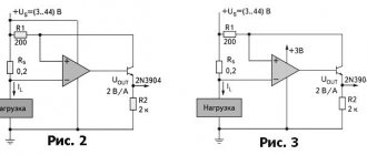
Simple current regulator circuit
The circuit includes a silicon diode . The transition voltage from it is used as a source of a reference signal, supplied through a limiting resistor to the non-inverting input of the microcircuit. To adjust the stabilization current of the circuit, an additional resistor is used, connected to the negative terminal of the power supply, to the non-inverting input of the MS.
The circuit consists of several components:
- A resistor supporting the op-amp with a negative terminal and a resistance of 0.8 Ohms.
- A resistive voltage divider consisting of 3 resistances with a diode serving as a reference voltage source.
An 82 kOhm resistor is connected to the negative of the source and the positive input of the MS. The reference voltage is formed by a divider consisting of a 2.4 kOhm resistor and a directly connected diode. After which the current is limited by a 380 kOhm resistor. The op-amp controls a bipolar transistor, the emitter of which is connected directly to the inverting input of the MS, forming a negative deep connection. Resistor R 1 acts as a measuring shunt. The reference voltage is formed using a divider consisting of a diode VD 1 and a resistor R 4.
In the presented circuit, provided that resistor R2 with a resistance of 82 kOhm is used, the stabilization current in the load is 74 mA at an input voltage of 5V. And when the input voltage increases to 15V, the current increases to 81mA. Thus, when the voltage changes by a factor of 3, the current changes by no more than 10%.
Charger for LM 358
Chargers with high stabilization and control of the output voltage are often made using the LM 358 op-amp As an example, you can consider a USB-powered Li-ion charger. This circuit is an automatic current regulator. That is, as the voltage on the battery increases, the charging current drops. And when the battery is fully charged, the circuit stops working, completely closing the transistor.
Categories: This is interesting
- How to charge a screwdriver battery correctly
- Miter saw with broach for wood: device, rating
- Wood planer for home workshop
- Circular wood saw: design and varieties
- Description, characteristics and choice of electric planer
What characteristics of the LM358 brought it such popularity:
- How to make a current stabilizer for LEDs?
- low cost;
- no additional compensation circuits;
- single or bipolar power supply;
- wide range of supply voltages from 3 to 32 V;
- Maximum output slew rate: 0.6 V/µs;
- Current consumption: 0.7 mA;
- Low input offset voltage: 0.2 mV.
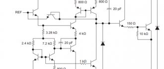
Comparator with and without hysteresis
The initial data for the calculation are presented in the tables.
Table. Initial data for calculating the comparator
| Entrance | Exit | Nutrition | ||||
| ViMin | ViMax | VoMin | VoMax | Vcc | Vee | Vref |
| 0 V | 5 V | 0 V | 5 V | 5 V | 0 V | 5 V |
Table. Thresholds
| Lower switching threshold VL | Upper switching threshold VH | VH–VL |
| 2.3 V | 2.7 V | 0.4 V |
Description of the scheme
Comparators are used to compare two input signals and generate an output signal depending on which of the input signals is larger (Figure 84). Noise or bounce on the input signals can cause the comparator to switch multiple times. To combat such switchings, hysteresis is used, which sets the upper and lower switching limits.
Rice. Comparator circuits with hysteresis (left) and without hysteresis (right)
We recommend that you pay attention to:
- a comparator with minimal intrinsic current consumption should be used;
- the accuracy of setting the hysteresis threshold values is determined by the accuracy of the resistor values;
- The response delay is determined by the parameters of the comparator used.
We recommend reading: Thyristors: principle of operation, testing and characteristics
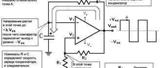
Principle of operation
To demonstrate how a high-speed comparator with hysteresis works, you need to take a circuit with two outputs.
The connection diagram, from which you can understand the principle of operation of the comparator, is shown above. Using an analog signal at the + input, called "non-inverting", and the output, called "inverting", the device uses two similar signals of opposite polarity. However, if the analog input is greater than the analog output, then the output will be “1” and this will turn on the open collector of transistor Q8 on the LM339 equivalent circuit to be turned on. But, if the input is at a negative level, then the signal will be equal to “0”, which is why the collector will be closed.
Almost always, a two-threshold or phase comparator (for example, on transistors, without an amplifier) acts on the inputs in logic circuits, and accordingly, operates at the level of a certain power network. This is a kind of transition element between analog and digital signals. This principle of operation makes it possible not to specify the certainty or uncertainty of signal outputs, since the comparator always has some capture of the hysteresis loop (regardless of its level) or a final gain.
Procedure for calculating a comparator with hysteresis
- Select the value of resistor R1 = 100 kOhm. The threshold voltage values were determined in the source data table: VL = 2.3 V, VH = 2.7 V.
- Let's calculate R2 using formula 1:
- Let's calculate R3 using formula 2:
- We check the obtained hysteresis value according to formula 3:
How to calculate a comparator without hysteresis
- We select the threshold value Vth = 2.5 V.
- We select the value of resistor R4 = 100 kOhm.
- We calculate R5 using formula 4:
Circuit Simulation
Timing diagrams of the circuit operation are presented in Figures 1 and 2.
Rice. 1. Timing diagrams of the circuit operation: noise is present only in the initial short time interval 0...120 μs
Rice. 2. Enlarged voltage oscillogram: interval 40…110 µs
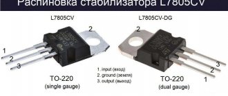
LM358 pinout
Since the LM358 contains two operational amplifiers, each with two inputs and one output (6 pins) and two contacts needed for power supply, a total of 8 contacts are obtained.
List of previously published chapters
- The Analog Designer's Cookbook: Op-Amps
- Inverting amplifier
- Non-inverting amplifier
- Inverting adder
- Differential amplifier
- Integrator
- Differentiator
- Transimpedance amplifier
- Unipolar current measurement circuit
- Bipolar current measurement circuit
- Unipolar current measurement circuit with a wide operating range (3 decades)
- PWM generator on op-amp
- AC Voltage Inverting Amplifier (Active High Pass Filter)
- Non-inverting AC voltage amplifier (active high-pass filter)
- Active bandpass filter
- Half Wave Inverting Rectifier
- Op-amp rectifier
- Low voltage rectifier with single supply
- Voltage rate limiter
- Differential signal generation circuit
- Inverting amplifier circuit with inverting input bias
- Non-inverting amplifier circuit with inverting input bias
- Non-inverting amplifier circuit with non-inverting input biased
- Inverting amplifier circuit with non-inverting input biased
Translated by Vyacheslav Gavrikov at the request of COMPEL JSC
•••
Analogs LM358
Along with the LM358, a large number of similar operational amplifiers are produced. For example, LM158, LM258, LM2409 have similar characteristics, but different operating temperature ranges.
| Type | Minimum temperature, °C | Maximum temperature, °C | Supply voltage range, V |
| LM158 | -55 | 125 | from 3(±1.5) to 32(±16) |
| LM258 | -25 | 85 | from 3(±1.5) to 32(±16) |
| LM358 | 70 | from 3(±1.5) to 32(±16) | |
| LM358 | -40 | 85 | from 3(±1.5) to 26(±13) |
If the range of 0..70 degrees is not enough, then you should use LM2409, however, you should take into account that its power range is narrower:
LM358 connection circuit: voltage-frequency converter
And finally, a circuit that can be used as an analog-to-digital converter. You only need to calculate the period or frequency of the output signals.
- C1 – 0.047 µF;
- DA1 – LM358;
- R1 – 100 kOhm;
- R2 – 50 kOhm;
- R3,R4,R5 – 51 kOhm;
- R6 - 100 kOhm;
- R7 - 10 kOhm.
Application
To assemble even the simplest voltage stabilizer for a charger, you need to have at least a little knowledge of physics. Otherwise, it will be difficult to understand the dependence of physical quantities, for example, how as the battery charges, the resistance of the battery increases, the charging current drops and the voltage rises.
Application
- pulse and pulsation generator (devices of the “flashing beacon” type);
- power supplies and chargers;
- split systems for indoor and outdoor use;
- motherboards;
- Appliances;
- balanced amplifier;
- bridge current amplifier;
- engine control circuits;
- uninterruptible power supplies;
- refrigeration units, dishwashers and washing machines;
- various types of inverters;
- controllers and more.
Manufacturers, as a rule, indicate the areas of application of the microcircuit in technical descriptions.
A simple current stabilizer charger made from scrap materials
There are a huge number of ready-made circuits and designs that allow you to charge a car battery. This article is on the topic of converting a computer power supply to an automatic car battery charger. It tells how to assemble an automatic current stabilizer with the ability to adjust the output current.
The stabilizer circuit used in our assembled charger is quite simple and is based on an open-loop operational amplifier (OP-amp) with a high gain.
The LM358 microcircuit is used as such an operational amplifier, or it would be more correct to call it a comparator. The image shows that it has:
- two inputs (inverting and non-inverting);
- one exit.
The job of the LM358 is to balance the output by increasing or decreasing the voltage at the inputs.
A charger or simple stabilizer is a device that:
- smoothes out network ripples;
- maintains a straight line of the current graph at the same level.
How is this done? In our case, a reference voltage is supplied to one input, set using a zener diode. The second input is connected after the shunt, intended to act as a current sensor. When a discharged battery is connected to the output, the current in the circuit increases and, accordingly, a voltage drop occurs across the low-resistance resistor. On the LM358 chip, a voltage difference appears between the two inputs. The device seeks to balance this difference, thereby increasing the output parameters.
Looking at the diagram, we see that a field-effect transistor is connected to the output, which controls the load. As the battery charges, the voltage at the terminals of the device begins to increase, therefore, it begins to increase at one of the inputs of the op-amp. A voltage difference arises between the inputs, which the op-amp tries to equalize by reducing the output voltage, thereby reducing the current in the main circuit.
As a result, the battery is charged to the required voltage, that is, the set value at the charger terminals. The voltage drop across resistor R3 becomes minimal or will not exist at all. When the voltage at the inputs is equalized, the transistor closes, thereby disconnecting the load from the charger.
A feature of this circuit is that it allows you to limit the charge current. This is done using a variable resistor, which is connected in series to the divider. And by actually turning the knob of this resistor, you can change the parameters at one of the inputs. The resulting difference is again equalized by increasing or decreasing the parameters.
There are no universal schemes. Someone is interested in the issue of increasing the load current. For example, what needs to be changed in the circuit for 15 A? It will be necessary to install a variable not 5, but 10 kOhm. By also making a preliminary calculation and replacing the corresponding elements, you can easily customize the circuit to suit your needs.
Gain adjustment
The previous design has one drawback - there is no way to adjust the gain. The reason is the complexity of the implementation, because you need to use two variable resistors at once. But if suddenly there is a need to adjust the coefficient, you can use a design circuit based on three op-amps:
Here the adjustment occurs using a variable resistor R2. It is necessary to take into account that the following equalities are satisfied:
In this case k=(1+2*R1/R2).
Amplifier output voltage U(out)=(1+2*R1/R2)*(Uin1-Uin2).