The NE555 chip, according to its main characteristics, is included in the category of universal timers. The range of time intervals that can be set in them is very wide. Most ne555 circuits contain square-wave pulse generators with different frequencies and lengths. The device, together with a small number of additional radio devices such as resistors and capacitors, is an integral part of various electronics. These are generators, PWM regulator on ne555, temporary ne555 relays, devices for simulating sound with different frequencies, etc.
Pinout NE555
The pinout of the device has not changed for many years, despite being used in different types of applications. The standard version usually has a DIP-8 plastic housing. Surface mounting is done using SOP-8 and SOIC-8.
The first pin is always marked as a small round depression or bulge.
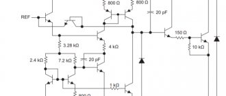
Previously there was an option in a round metal case LM555CH, but it is no longer produced. It consisted of an RS trigger, two comparators, a discharge transistor and an inverting amplifier.
Manufacturers
The considered universal timer, created by the American company Signetics back in 1971, still continues to be produced by almost all well-known global brands in the semiconductor industry. At the same time, the labeling of its complete analogues from different companies may differ from the original, despite complete functional and physical identity. For example, judging by the datasheet NE555 P (aka LM555P) and NE555N are the same device from two competitors: Texas Instruments and STMicroelectronics, respectively. NE555L is a product of China's Unisonic Technologies Co (UTC). Japanese Motorola once made CMOS versions with the designation MC1455. Currently, the process of its improvement and modernization to meet modern requirements continues.
Limits of permissible values
There are a number of typical maximum operating specifications for the NE555. They are found in the most common modifications of this microcircuit. Their differences depend only on the manufacturing company, but, as a rule, are the same in most technical descriptions:
The voltage of the energy source is from 4.5 to 18 Volts.
Power dissipation: 600 microwatts.
The output current is 200 milliamps.
Operating frequency - 500 kilohertz.
Temperature for operation - from 0 to 70 degrees, for storage - from -65 to 150 degrees.
If the specified parameters are exceeded, the device may fail.
P O P U L A R N O E:
- Electronic Cigarette
Homemade battery pack for electronic cigarette
An electronic cigarette is a device that imitates the process of regular smoking, but saves the smoker from inhaling tar and other combustion products, and it also allows you to change the dosage of nicotine. An electronic cigarette is a tube, slightly longer than a regular cigarette, consisting of a battery, an evaporator, a microprocessor that controls the evaporation process, and cartridges with an aromatic liquid - usually a mixture of nicotine and propylene glycol. The tip of the cigarette lights up during a puff as the smoker inhales the “smoke.”
Read more…
Sound turn signal
In order not to forget to turn off the turn or handbrake lever, I suggest adding a simple device to your car - a signaling device. The sound alarm is assembled on a common and inexpensive K155LA3 microcircuit. The signaling device is connected to the turn signal or handbrake warning lamp. Read more…
DIY subwoofer
How can I replace NE555?
In Soviet times, there was a complete ne555 analogue of the microcircuit - KR1006VI1. Today it is produced in Latvia and Belarus. The Russian-language instructions for it provide information that fully corresponds to the English version of the ne555 datasheet.
There is one point that is important for selecting a quality replacement. In the specified version of the device there is a priority for the operation of the “stop” outputs over the “start”, but in the original version the situation is the opposite. Most common schemes do not have this functionality, but you should not completely discount it.
Such a microcircuit is an unfinished product with the implementation of 2 operating modes:
Monostable - start timer.
A multivibrator that generates single pulses.
In order for the device to operate in one of these modes, it needs to be slightly improved. For this purpose, an RC circuit is placed between the contacts with a capacitor and resistor selected in advance. Their indicators set the desired frequency ne555 and the periodicity of rectangular signals at the output of the device when power is applied to it. To increase the accuracy of operation in order to avoid external interference, it is necessary to carry out shunting with a capacitance of no more than 0.1 μF.
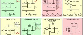
Application
The incredibly low price, availability and ease of implementation of functionally complex and at the same time trivial electronic circuits based on it, without deep knowledge in the field of electronics, have made it the most favorite toy of most novice radio amateurs. It is the heart of a wide variety of and very popular designs, including those made by yourself.
Using the instructions in the short video, you can assemble some of the circuits on the NE555: a simple and more advanced pirate metal detector, a PWM regulator, a boost DC converter and an inductance and capacitance meter on a Schmitt trigger.
Ne555 - connection diagrams
NE555 operation in timer mode
Requires 2 additional items:
Resistor.
Two containers.
When power is applied, the 3rd leg relative to ground level will have a voltage of 0 Volts. The capacitor that sets the time has no charge, and the circuit can remain in this state for a long time until a positive signal arrives at the second contact. Its value should be three times less than the supply voltage.
When a signal is applied to pin 2, the output of the microcircuit receives a voltage at the supply level. Its length is determined by the charge time C. When this happens, the output voltage decreases to almost zero and the device discharges.
It is important for the circuit that, once it is turned on, no influences on pin 2 change the output voltage level. But it can be reduced by applying a signal to the 4th leg. You can calculate the time interval of the output pulse using the formula: T=1.1*Rt*Ct.
Operation in multivibrator mode
ne555 produces square wave signals. Their periodicity depends on the values of the time-setting RC chain. The design changes slightly, adding additional resistance. Pin 7 connects resistors Ra and Rb, but is switched off inside the timer.
When power is applied to the chip, the output goes high relative to ground, and the capacitor begins charging. When Ct reaches a charge of 2⁄3 of the supply voltage, the circuit switches and the output voltage decreases to 0. Then contact 7 is turned on and the device is discharged.
Device operating modes
The 555 chip has three operating modes:
- Monostable mode of the 555 chip. It works as a one-way single-ended. During operation, a pulse of a given length is emitted in response to the trigger input when a button is pressed. The output remains at low voltage until the trigger turns on. Hence it received the name waiting (monostable). This operating principle keeps the device inactive until turned on. The mode enables the inclusion of timers, switches, touch switches, frequency dividers, etc.
- Astable mode is a stand-alone feature of the device. It allows the circuit to remain in regenerative mode. The output voltage is variable: sometimes low, sometimes high. This scheme is applicable when it is necessary to give the device shocks of an intermittent nature (when the unit is turned on and off for a short time). The mode is used when turning on LED lamps, operates in a logical clock circuit, etc.
- Bistable mode, or Schmidt trigger. It is clear that it operates using a trigger system in the absence of a capacitor and has two stable states, high and low. The low trigger value becomes high. When the low voltage is released, the system rushes to a low state. This scheme is applicable in the field of railway construction.
Main features and disadvantages of the NE555 timer
The main distinguishing feature of the device is the presence of a built-in voltage divider. It sets the upper and lower threshold values at which 2 comparators are triggered. Since it cannot be removed, this limits the applicability of the circuit.
A timer with bipolar transistors has one obvious disadvantage regarding the transition of the output stage between states. When switching, a parasitic through current passes through the device. At its peak it reaches 400 milliamps, which leads to an increase in heat losses.
To solve this problem, you need to install a polarized capacitor. It has a capacitance of no more than 0.1 µF between the wire and the control pin. This stabilizes the device during startup and during operation in general. To make noise immunity even higher, a 1 µF capacitor is included in the power circuit.
Timers based on CMOS transistors do not have these problems. They do not require external installation of capacitors.
Analogs
Since 1975, the KR1006VI1 series product has been created as an analogue. The production of the design continues in Riga (Republic of Latvia). Production by Belarus has also been preserved since the post-Soviet period (USSR). Their production “Integral” continues to produce products, only the marking makes it distinctive, the IN555 series.
Note! The product KR1006VI1 in Russian completely repeats the English versions (datasheet 555).
Placement and purpose of pins
The NE555 and transistors that can be used to replace it typically have an eight-lead PDIP8, TSSOP, or SOIC package. The terminals, regardless of the type of housing, are located standardly.
The timer is graphically indicated as a rectangle and labeled as G1 (single pulse generator) or GN (multivibrator).
Types of conclusions:
- GND - common. This is the 1st pin in relation to the key. It is connected to the power supply section of the device with the “-” sign.
- TRIG - launch. When a low pulse is applied to the input of the 2nd comparator, the device starts and a high level signal appears at the output. Their length is affected by the rating of external parts C and R.
- OUT - output. The voltage at a high signal level at the output is 1.5 V, at a low level - 0.25 V. Switching is 0.1 μs.
- RESET - reset. This input has maximum priority. It controls the operation of the device at any voltage on the other terminals. Startup permission is possible at a potential of 0.7 V. Because of this, it is connected to the device’s power supply using a resistor. If a pulse of less than 0.7V appears, the NE555 stops working.
- CTRL - control. Directly connected to the voltage divider, and without external influences, 2/3 Up is supplied. When the ne555 control signal is applied to the pin, signal modulation is obtained. In standard circuits, it is connected to an external capacitor.
Twenty timers [NE555]
You don't need a controller, they said. Do everything with NE555 timers, they said. Well, I did it - it seems, only to make sure that the result was a design that was stunning in its crushing effect on my fragile psyche. The review, if this text can be called that, will not be too long. Because it only states my complete and unconditional failure in assembling elementary circuits and demonstrates that at least six out of twenty chips are quite functional.
Also note: it seems that the store recently changed the rules, since now they have a minimum order with free delivery of $6, and if less, then they will charge $1.5 for delivery. When I bought, they only wrote off the purchase price, that is, $0.59, and that’s it.
There are exactly twenty pieces in two blisters. On one side, each blister is wrapped with tape, on the other it is closed with a rubber stopper:
In general, I initially bought timers to make a simple generator to find a short circuit in the wiring - my friends were interested. The essence of the device, if I understand correctly, is that the circuit up to the short circuit is an antenna, the signal from which can be heard with a regular MF/LW receiver.
Where the squeaking stops is approximately where the short circuit occurs. This is what it looks like in practice for a friend in whose footsteps I planned to follow:
But then those familiar with the need decided that they didn’t really need everything. Or they decided something else, but I didn’t insist. And be upset too: you’ve seen how much timers cost (a little more than half a dollar for 20 pieces) - what a disappointment?
Regular DIP8:
Therefore, I decided to have fun in a different way and looked at what they were making out of NE555. And, as it turned out, they do a lot of things. All kinds of alarms, voltage indicators, missing pulse indicators. Overall, I was impressed.
Well, since everyone is describing approximately the same thing, here are a couple of RadioKat links: one and two. Schemes are in the second.
It is assumed that the popularity of the NE555 is due to the fact that it is a design that has been proven over the years (more precisely, for 45 years), which is disconcertingly simple to configure and quite accurately adheres to the characteristics regardless of the supply voltage, which can be in the range from 4.5V to 16V for the regular version (but there are options). That is, the voltage fluctuates, but the frequency is more stable than not.
In fact, to make the timer work, you need a couple of parts and any suitable power source - very attractive for making some shit without much hassle.
As for me, with a microcontroller there is even less hassle, but in the comments to the story about “Pishchal” I received a hint that such things are usually done on the NE555 and I lost my peace. I realized that I had to try at least to calm down.
So, the idea was simple - a cat feeding timer. Who, having lost all shame, began to demand food almost every half hour, and after eating three crackers, they left satisfied. According to the veterinarian, this is not very useful (and in our opinion, it is also extremely troublesome), so it was necessary to return their diet to its place. Well, that’s a good idea: feed at least no more than once every five to six hours.
Keeping track of the clock, of course, is not difficult. However, firstly, the situation is complicated by the fact that if during the day feeding by the hour goes on more or less, then at night it is no longer quite so, since one cat has, let’s say, a complex character. Exactly - he goes and scratches the radiator with his claws, and even if I decided not to pay attention to this musical experiment of dubious quality, I feel sorry for the neighbors.
That is, at night you have to get up and time it again, and in a semi-conscious state this is a little difficult.
Secondly, not all cats are so scandalous, so some simply do not come along with that troublemaker. And it turns out that the intervals are different for everyone, but in fairness it would be nice to feed at a set time also those who missed an extraordinary meal.
Therefore, I came up with the idea of making a bunch of independent timers for a fixed time - one per cat. And just like this: a cat comes, you give him food, you press the button, the light comes on. Just like the light bulb went out, the cat can be fed again.
As you might guess, this is one of the main options for the timer. You can call it differently: you can call it a tracing paper from the documentation - monostable, you can call it a monostable, you can call it a waiting multivibrator.
This does not change the essence: the NE555 is required, in fact, to issue only one pulse of the required duration.
Therefore, I took the timer circuit from the RadioCat examples as a basis:
But I simplified it a little by getting rid of the trimming resistor (since I have a fixed interval) and the second LED - as unnecessary. At the same time, I changed the values of the timing chain, checking with the same documentation, which reports that to calculate the approximate pulse duration, you should use the formula yt = 1.1RC.
Having played with the fonts and the values of the parts available in the Chip-i-Dip boutique, I found that for a five-hour interval that suits everyone, a capacitor with a capacity of 3300 μF and a resistor of 5.1 MΩ are quite suitable:
t = 1.1*0.0033*5100000 = 18513 sec = 5.14 hour.
The reality, however, turned out to be slightly different from the theory. The timer, assembled according to this scheme and with these values, continued to work after five hours. I didn't have the patience to wait for it to finish working, so I assumed that the NE555 doesn't work very well with large denominations.
A quick googling showed that yes, it is possible, but there should be no problems (theoretically) with a resistance of up to 20 MOhm at a supply voltage of 15 V. Therefore, I continued experimenting and found out that in my case the formula turns out something like this:
t = 1.45*C*R.
And I was very grateful to myself that I bought not only 5.1 MOhm, but also, just in case, the closest ratings - 4.7 MOhm and 3.9 MOhm. The latter, fortunately, was just right for the required interval.
With these ratings (3300 µF and 3.9 MOhm) I assembled a block of timers with lights and buttons. I connected everything with a common power line; they have no other points of contact (well, at least I tried not to). And since I was assembling the canopy, I checked myself with a multimeter at every step and was almost calm when I started the first of the timers.
It turned out like this (I warned you at the very beginning):
It turned on as expected, so I unsoldered the remaining buttons and lights and turned it on. I pressed buttons. The LEDs turned on exactly as they were supposed to: you press the button - it turns on, and that's it.
And then I made a big mistake. I didn’t do a few more test runs, but was just upset that I didn’t solder the wires to the buttons very well, and decided to resolder them. Therefore, I don’t yet know what exactly happened: either I did something wrong initially, or I managed to ruin something while resoldering the wires.
But it turned out funny. When turned on again (with the wires soldered), three LEDs immediately lit up. And pressing the buttons revealed complete chaos: you press one button - its LED lights up (i.e., in theory, the timer turns on), you press another - the first LED goes out, the second lights up. And so on.
I found out empirically that there is a certain combination of button presses that lights up all the LEDs. But so far I haven’t gotten around to checking the circuit for short circuits where there shouldn’t be any.
Bonus track - let's play minesweeper:
To summarize, I want to say that I had fun with timers. In practice, I checked that you can buy them in China - workers come.
And although I couldn’t make the cat timer, I got the “Light all the light bulbs” puzzle as a bonus. And at the same time, the understanding that NE555 is clearly not for me. And that's why:
- minimum supply voltage 4.5V - high current consumption
Of course, these shortcomings can be overcome by ordering the CMOS version of the chip, which is much more economical and works starting at 1.5V. But regular ones cost $0.59 for twenty pieces, and CMOS ones cost about $10. That is, the controller is approximately twice as expensive, and if two or more timers are used in the design, the benefit disappears altogether.
So thank you all, I'm going back to the ATmega328p, on which, obviously, I will make a feeding timer.
ps. And now can I also write about the screen from ITEAD Studio? By the way, my conscience is tormenting me, because, on the one hand, these screens here were already through the roof, and on the other hand, we must fulfill the promise.
How to make a ne555 metal detector with your own hands
There is a way to make a homemade metal detector from 2 ne555 circuits. They consist of 2 coils:
- Transmissions - Tx.
- Reception - Rx.
The entire structure is divided into 2 blocks. The first one, which is on the left, consists of a square wave generator. The time-setting elements (R1, R2, C1) are selected so that the approximate output frequency is 700 Hz. It is called the frequency of the audible spectrum.
Pulse transmission occurs through a current-limiting resistor - R3. The location of two coils in the same area is such that they together form an overlap and the system has an induction balance. The receive coil voltage is zero, and there is no reaction from the right side of the circuit. If there is a metal object nearby, the balance is disturbed and a sound is heard.
To amplify the signal arriving at the input of microcircuit 2 of the receiving coil, transistor VT1 is used, namely, KT3102EM, or its analogue with any amplification level. The resistors form a voltage amplifier. Using variable resistors, the metal detector is adjusted to ne555. R6 - for adjustment, adjusted after mutual placement of the coils. R7 and R8 help make fine adjustments and are installed in the device housing.
The piezo emitter BA1 is involved in the recognition of the sound signal. It is removed from the unusable multimeter. It is desirable that it has an internal generator. The pulse signal generated at the DD2 output signals and helps to detect small changes in sound when a metal object is nearby.
How to make a reel
To wind the metal detector coils, you need to use an enameled winding wire with a radius of 0.16 mm. Pick up some large object and wrap it around it. The wire can be obtained from an unnecessary electric motor or power transformer.
Take out the wound spool and wrap it with paper adhesive tape. You should get 2 identical coils. Scotch tape is needed because over time the winding loses its shape. It is advisable to make them flattened, resembling the letter D, so that one does not overlap the other. The base for the coils can be a sandwich panel, often used in plastic windows. The coils can be connected to the board using a shielded wire.
Practical examples
The scope of practical application of the timer is wide; within the framework of this review it will not be possible to fully cover the topic. But the most common examples are worth examining.
In one-shot mode, on several microcircuits, you can build a combination lock with a time limit for dialing the code. Another way is to use it as a signaling device for reaching a threshold level (illuminance, container filling level, etc.) in conjunction with various sensors.
Watch this video on YouTube
In multivibrator mode (astable mode), the timer finds the widest application. Using several timers, you can build a garland switch with separate control of the blinking frequency, on time and pause time. You can use NE555 as a basis for a time relay and set the switching time for consumers from 1 to 25 seconds. You can build a metronome for a musician. This is the most used mode of the chip, and it is impossible to describe all the uses.
The timer is rarely used as a Schmitt trigger. But in bistable mode without frequency-setting elements, the NE555 is used as a contact bounce suppressor or a two-button switch in the start-stop mode. In fact, only the built-in RS trigger is used. It is also known about the construction of a PWM controller based on a timer.
There are collections of circuit diagrams that describe various applications of the NE555 timer. They describe thousands of ways to use the chip. But even this may not be enough for the inquisitive mind of the designer, and he will find an additional, not yet described use of the timer. The capabilities provided by the chip developers allow this.
How the TL431 microcircuit works, connection circuits, description of characteristics and performance testing
What is a trigger, what is it for, their classification and operating principle
What is a voltage comparator and why is it needed?
Description of characteristics, pin assignments and examples of circuit diagrams for the linear voltage regulator LM317
How to make a time relay with your own hands?
Description, characteristics and connection diagram of the voltage stabilizer KREN 142
Diagram of a regular flasher on NE555
This device operates in a multivibrator mode that generates rectangular pulses. Their length is changed by selecting capacitors and resistors. The circuit consists of 2 alternately switched LEDs. But if you only need 1 of them, the second one does not have to be included in the microcircuit; this will not affect the quality of operation of the entire device.
The circuit is powered from 3V, and can range from 3 to 15. When increasing the power, you need to select resistors for the LED circuits. If the power comes from 12 V, the resistors should be 1.5 - 2 kiloOhms.
The assembled flasher does not need to be configured; it works when turned on. It is not necessary to take a 220 kiloOhm resistor; soldering in an alternating or tuning version is enough. This will help you set the LED blinking frequency.
You can use a breadboard to assemble the circuit. Since the number of components in it is minimal, wall-mounted installation can be used. This technique is relevant for motorists.
Functionality check
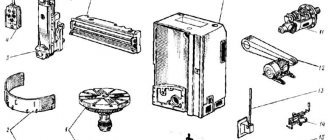
For your homemade products, NE555 can be desoldered from old, unnecessary or already faulty equipment. It is found in control panels, thermostats, temperature regulators, Christmas tree garlands, light and music and various devices with a time delay, car tachometers, etc. If you are lucky and managed to find it, then before using it in your electronic designs, you need to determine its functionality.
You can't check with a multimeter. Therefore, for these purposes they usually use a simple tester - also known as an “LED flasher”. If, after connecting the power, both diodes blink alternately, then the NE-shka is working. Otherwise, it is faulty.
How to make a ne555 time relay yourself
To become more familiar with the timer, make a time relay yourself. This is a simple, classic circuit that anyone can assemble.
To start, toggle switch SB1 is used, and resistor R2 is used to adjust the duration. The approximate operating time of this circuit is 6 seconds. To increase it without changing the characteristics of R2, you need to increase the capacity of C1.
For a daily operating cycle, you need to use a capacitor with a capacity of 1.6 thousand microfarads. When using the microcircuit in conditions close to real ones, the farads can be changed to more appropriate ones for the required working time. For the calculation, use the formula: T=C1*R2, C1 is the capacitance of the selected capacitor, R2 is the average resistance of the adjustment resistor.
The pinout looks like this:
- GND (Ground) - power is reduced.
- Trigger - the contact receives a pulse to start the timer. Occurs when a toggle switch is pressed.
- Output – when the timer is active, an outgoing signal is generated at the contact.
- Reset - A negative signal is given and the timer is stopped.
- Control Voltage - increases the device's resistance to interference.
You can purchase NE555 on Aliexpress (follow the link) and in other online stores at the most affordable prices.
Power circuit
In Fig. Figure 2 shows the power supply diagram. The 230 V, 50 Hz AC mains is disconnected from transformer X1, providing a secondary output of 9 V, 500 mA. The output of the transformer is rectified by full-wave rectifier BR1, filtered by capacitor C7 and regulated by IC 7805 (IC8). The thus obtained regulated direct current of 5 V is additionally filtered by capacitors C8 and C9. LED3 acts as a power indicator. Resistor R14 acts as a current limiter. A capacitor above 10uF is connected to the output of the regulator IC and diode D1 protects the regulator IC in case its input is shorted to ground.
Fig.2: Power circuit
What determines the duration of the pulses?
Three elements are responsible for the duration of the low and high states at the output of the circuit: R3, R4 and C3. In particular, resistor R4 and capacitor C3 are responsible for the duration of the low state (i.e. when the green LED is on). The higher the resistance of R4, the longer LED1 will burn.
The duration of burning of the red diode, signaling the presence of a high state, is determined by the total resistance of R3 and R4 and capacitance C3. Thus, increasing R3 will prolong the duration of the high state, and increasing R4 will do both. Therefore, the red diode burns longer than the green one - the sum of resistances R3 and R4 will always be greater than the resistor R4 itself.
| It is not allowed to put a “short” in place of resistor R3, i.e. replace it, for example, with a wire. No amount of resistance at this point will destroy the IP. |
Capacitor C3 affects both of these states equally. The larger its capacity, the less often the diodes will switch, and the smaller it is, the more often changes will occur.
What role does the second capacitor play?
On the circuit diagrams of many NE555s there is a small capacitor (about 10 nF) connected between pin 5 and ground. It filters the voltage generated in the upper resistive divider node. Some say that this capacitor is redundant because the entire circuit is powered by a constant voltage anyway, so the potential of this node cannot change.
The above reasoning is valid until the RS flip-flop switches. However, this short moment, during which a lot happens in the circuit, must be constantly monitored by comparators. The reference voltages produced by the divider resistors should not be changed because this will affect the duration of the pulses.
For this reason, it is recommended to add a 10-100 nF ceramic capacitor, which easily blocks sudden changes in this voltage - creating an RC filter. Long-term changes, such as the battery slowly draining, will not be blocked by it and will not disrupt the operation of the circuit.