Widest scope of application
The simplicity of assembly and high efficiency of transformers became the reason for their inclusion in the composition:
- Power supplies;
- TVs;
- Microwave ovens;
- Radio stations;
- Welding machines;
- Communication equipment;
- All kinds of automation
- Control and measuring equipment.
Classification of varieties
All types of air transformers come down to two groups:
- Impedance, used to match the voltage drop values at the source and load consumer in order to ensure the most efficient energy transfer;
- Isolators, which are used for safety reasons to isolate a piece of equipment from an energy source.
In air transformers, all currents are considered exciting. They induce a secondary voltage, the value of which is comparable to the total inductance of the electrical system. Therefore, the core base material has the highest magnetic permeability. Such materials also include glass, porcelain, mica, and some types of plastic.
However, only electrical insulating cardboard GOST 2824-86 is distinguished by a favorable combination of strength (electrical and mechanical), density and resistance to changes in environmental humidity.
Personal assembly
Many radio amateurs and simply curious people periodically ask how exactly to assemble this or that transformer on their own.
Despite the simplicity of solving this problem, you still need to have some skills in working with radio components and understand the physical principles of operation of this device.
Naturally, you will first have to carefully study the entire technology:
- Core preparation;
- Winding coils;
- Applying layers of insulation.
What material is the magnetic circuit made of?
If you need a low-power converter, a rod or armored magnetic circuit is suitable. In the first version, the rods are located vertically. In the second case, the rods have a rectangular cross-section and are located horizontally. This design is more complex and therefore less common.
In step-up, W-shaped ferrite magnetic cores are often installed; the difficulty in the design lies in the need to select the exact size of the rod. If a spare part from another equipment is used for assembly, the thickness of the plate package is determined based on the power. The plates are inserted into the coil and tightened with nuts and studs.
Clarification of a number of technical parameters
However, before starting the practical part, you will need to give clear answers to a number of questions.
- How exactly should the future unit change the current: increase it or decrease it?
- What voltage will be supplied to the primary coil and removed from the secondary?
- What will be the operating frequency of this device?
- How much power should it have after assembly is completed?
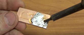
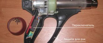
Making the adapter
Quite often, the power supply of a power tool breaks down. You can purchase a new battery, which is not cheap. An adapter in the form of a power supply made on the basis of a transformer will help save money.
Required Components
To convert an electronic converter into a power supply, you need to buy the following parts:
- Circuit board.
- Overheat protection element NTC 4 Ohm.
- Resistance 6.8 Ohm, 5 W – 2 pcs.
- Resistance 500 Ohm, 2 W.
- Capacitance with parameters 100 µF, 400 V.
- Capacitance with parameters 100 µF, 63V.
- Film capacitor 100 nF.
- Rectifier device KD213B – 4 pcs.
- Metal plate for cooling diodes.
- Toroidal element made of ferrometal.
- Copper wire 1.2 mm².
Having prepared all the necessary components, you can begin to convert the electronic transformer into a power supply.
Algorithm of actions
The following steps must be followed sequentially:
- Shunt the rectifier output with a capacity of 400 V, 100 μF. To reduce the charging current of the container, add an NTC 4 Ohm overheat protection element to the open circuit. If this is neglected, the rectifier will fail when connected to the network.
- Replace the secondary winding of the matching transformer with a shunt. Wind 2 turns onto the power transformer, and 1 turn onto the matching transformer. To connect the turns, solder two parallel-connected 6.8 Ohm resistors.
- Wind 24 turns of copper wire onto the ferromagnetic rod and secure it with heat shrink tubing or tape. The result was a choke.
- On the mounting plate, assemble the remaining elements according to the diagram, and connect the assembly by soldering to the corresponding terminals of the transformer. Select the body and fix the structure in it. The power supply is ready for use.
After the process is complete, turn on the power supply and test. The device must output 12 V.
The benefits of a detailed drawing
After providing comprehensive answers to the above questions, a diagram of the transformer device can be drawn up on paper or on a computer. It is not superfluous to do this even with a clear understanding of all the parameters and features of the radio component.
Often a drawing allows you to significantly clarify
- Scheme of connecting and bringing out contact wires;
- Number of plates in the W-shaped core;
- Method of arrangement of primary and secondary coils.
Cutting
Cutting occurs after applying the coil drawing to the material. This is done using a regular construction pencil or even a marker.
The tools needed for cutting vary depending on the thickness of the PCB. For sheets up to 1.5 millimeters, whose cutting is carried out in a cold state, guillotine shears are used. And if the sheets are thicker, then a circular saw is used. Textolite with a thickness of 3 millimeters or more is sawed at a temperature of 80 degrees Celsius with a saw.
Purchase of components and consumables
After the schematic diagram has been fully prepared, you can begin purchasing the parts and consumables needed for assembly.
Usually, the necessary materials and accessories, including varnished wire and terminals, are easy to find in the first radio store you come across.
First you need to buy
- Electrical tape or heat-resistant tape;
- Core configuration corresponding to the project;
- Insulated wires.
How to make and assemble an air transformer
Pre-determined with the core material. When using electrical cardboard, it is necessary that its performance characteristics comply with the following standards GOST 2824-86:
If other materials are used, their physical and mechanical characteristics must be no lower than those listed above.
Coils of insulated copper wire are wound around a plastic tube or hollow torus. For the adopted core configuration, its moment of resistance is taken to be greatest for a given external cross-sectional size: this provides the winding with the necessary mechanical support. The copper winding around a torus or cylinder can, if necessary, be carried out to different points, from where the secondary voltage is removed.
Sometimes, in order to maintain a constant resonance in the tuning circuit, a capacitor is additionally connected to the winding. Magnetic flux flows through the air surrounding the winding and the air present inside the hollow core.
To correctly match the voltage drop values, a protective winding is also wound on top of the main copper winding. It is connected to the antenna receivers and properly grounded.
Toroidal cores have an advantage over cylindrical ones, since the influence of stray coupling is minimal here. Air transformers of this design are used in particularly high-frequency applications.
Source
Assembling the winding machine
When making this electrical device yourself, you will need to wind the wire. Winding a transformer with your own hands is carried out on a simple homemade machine tool. You can do it in a couple of hours.
First you need to take a board measuring 10x40 cm. A couple of bars measuring 50x50 mm should be attached to this base with screws. The distance between them should be at least thirty centimeters.
Reel Rods and Handle
Next, miniature holes with a diameter of 8 mm are drilled. Rods are inserted into them onto which the transformer coil will be strung.
- All that remains is to apply a small diameter thread, tighten the washer and mount the handle.
- It is important to note that the dimensions of such a machine can be anything.
- In other words, it can be fully adapted to the intended core size.
- However, if the project involves the use of a ring core, then it will have to be wound entirely by hand.
What power will it have?
Once you can answer each of the questions listed, purchase the required materials. You can easily buy the necessary materials in specialized stores. You will need wires, premium quality tape insulation, and a core.
The transformer itself requires winding. For these purposes, a machine should be created, the manufacture of which is carried out from a board forty centimeters long and ten centimeters wide. Several bars need to be attached to the board using screws.
The distance between the bars should not be less than thirty centimeters. Then you should drill holes eight millimeters in diameter. In the created holes you need to insert special rods for the device’s coil.
A thread should be created on one side. By tightening the equipped washer, you will get its handle. The dimensions of the winding machine can be chosen at your own discretion. First of all, the right choice directly depends on the size of the core. With its ring-shaped form, the winding is created manually.
According to the diagram of the transformer device, the device can be equipped with a varied number of turns. The required quantity is calculated based on power. For example, if it is necessary to create a device up to 220 volts, the power should reach at least 150 watts.
The shape of the magnetic wire should be O-shaped. You can make it out of a used TV. In this case, the cross section is determined using a certain formula.
Effect of power on the number of turns
A transformer made by yourself can be equipped with any number of turns.
The instructions on how to make a transformer indicate that the required number of turns is calculated based on the power of the intended device.
Marking
Marking is the first stage, which is carried out if materials and tools are available. Careful research is important to determine the technical specifications.
It is acceptable to do it manually using special tables (but note that in this case you will have to calculate everything yourself using formulas).
You can also select markup using programs - there are some available for free on the Internet. But in this case, a novice radio amateur will not be able to understand the calculation algorithm and learn how to perform the frame independently, without the use of computerized equipment.
How to do it manually
Testing of strength and fastening features is carried out experimentally. A coil is taken, or rather a sample of it, which you wouldn’t mind throwing away, and 10 turns are placed on it, which will be used for the main transformer.
A rod is selected with a diameter four times larger for wires with a thickness of 0.96 millimeters, five times larger if wires up to 1.56 millimeters are taken, and six times thicker if the wire thickness exceeds 2.44 millimeters. This must be taken into account; the selected instructions are available in special technical literature.
Separately, it should be taken into account that in addition to a certain bend, which certainly forms stronger in the first few layers, and then begins to round off, there is also a strong tension and stretching. When marking the frame, take into account that the multiplicity increases several times. For example, for a wire that is 1 millimeter thick, the radius of curvature will be about 5 millimeters. Radii for wires of any diameter are also placed in the corresponding tables.
Class selection
Carrying out markings according to samples allows you to avoid the appearance of loose and uneven surfaces in the winding. Thin getinax is used if it is necessary to increase the rigidity of the frame. For example, if the device power is up to 10 W, then the sizes of small parts will be 0.5, medium - 0.7 to 1.5, and large ones - from 1. Power up to 100 W implies the use of 0.7 - 1, 2, 0 - 4, 1 - 2 mm parts, respectively. For devices with power ratings from 100 to 500 W, take up to 1 to 2 mm for class a, from 3 to 6 for b, from 1.5 to 3 for class c.
For the latter type, with the highest power ratings, it is advisable to increase the radius of curvature by approaching the optimal rounding values. It is better to take special inserts made of material that is used for twisted magnetic wires. They are used if the thickness of the magnetic circuit is twice as thick as the working rod of the device.
Additionally, most of the protruding part of 3 millimeters is installed on the part. This is necessary so that the cheeks of the frame are firmly attached to the equipment. The sleeve is made slightly larger in size than the working rod by 0.5 mm, the gaps should not exceed this figure. Be sure to take into account whether the frame is obtained using hardware or whether it is supplied with the device.
Calculation using programs
There are several dozen programs on the Internet, most of them freely available, that calculate the transformer and its frame. In particular, the CARCASS program is popular, from version 1.0, 2.0 and onwards. It works online, but if you wish, you can download the file and install it on your computer. The program contains information about:
- core type;
- thickness of material and screed;
- core sizes A, B, C, N.
After entering all the information, press the “Enter” or “Calculate” button. The calculation will also appear on the coil line, which can be printed and applied to the available textolite. There is an option designed for a frame with a lock.
Computing application for Android
Mathematical expressions that can be found in specialized literature will provide reliable assistance in clarifying a number of parameters. Almost all of these formulas have already been included in computer programs, which in most cases makes it possible to minimize the calculation part.
You just need to specify some data about the future device in the program interface, and the smartphone application will display a comprehensive table with the requested information.
Electrical specifications
To correctly make a model yourself, a number of parameters are determined:
- Output power: P2 = U2*I2, which is obtained by multiplying the output parameters. If there are several secondary coils, they are summed.
- The efficiency does not exceed 80%, so the primary: P1 = P2/0.8 = 1.25*P2.
- The area of the central part is calculated based on P1. For steel, this value is: S = P1^0.5 - calculate the root of the primary power value. For tin, baked wire, roofing iron, S is taken three times more: S = 3*P1^0.5.
- Turns of the first coil: w1 = 50/S.
- Second: w2 = w1*U2.
The w value is increased by 5-10%, because Some voltage is lost due to resistance.
Frame production stage
The frame part is made of cardboard. Those who do not yet have experience in such assembly and therefore do not know how to make a transformer frame with their own hands must take into account that its internal part must have larger dimensions than the core.
If a ring-shaped core is used, there will be two coils. When choosing an W-shaped core configuration, there will be only one coil.
Arrangement of the reel housing
The body is made of high-quality cardboard paper. Its inner side is slightly larger compared to the core part of the core. When using an O-shaped core, several coils will be required. With a w-shaped core, it is enough to use only one coil.
When using a round core, it should be wrapped using insulation. Then you can carry out wire winding. Once you are done with the primary winding, it should be covered with several insulating layers. After this you need to wind the next layer. The ends of the existing windings are brought out to the outside.
When using magnetic wire, the transformer body is assembled step by step:
- A certain size of sleeve with the required cuffs is cut out.
- Cardboard cheeks are created.
- The main part of the coil is rolled up into a special box.
- Cheeks are placed on the sleeves.
Winding wire and applying insulation
If a round core was chosen as the base, then it should first be wrapped with electrical tape. Next you can start winding the wire.
- After the application of the primary winding is completed, it is covered with dense insulation.
- Then it’s time to wrap the second layer.
- The ends of the windings are brought out, and contacts are soldered to them for interfacing with other equipment.
Calculation of product parameters
Before winding a toroidal transformer at home, you will need to calculate its values. To do this you need to know the source data. These include: the output voltage, the outer and inner diameter of the core.
The power of the device is determined by the product of the areas S and Sо, multiplied by the coefficient: P=1.9* S * Sоk.
The cross-sectional area is calculated using the formula: S=h*(Dd)/2, where:
- S - cross-sectional area;
- h - height of the structure;
- D - outer diameter;
- d is the internal diameter.
To calculate the window area, the formula is used: Sok=3.14*d2/4.
The number of turns in the secondary winding is equal to the product W2=U2*50/Sok.
Next, it remains to calculate the number of turns in the primary. For this, the expression is used: W1=(Uin*W2)/Uout, where Uin is the input voltage, and Uout is the voltage at the output of the device.
This calculation method can be applied to almost any type of toroidal transformer. But for the calculation of some products there is its own methodology.
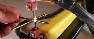
Welding device
This type of transformer is characterized by a high output current. The maximum current and voltage are used as input parameters. For example, for a device with a welding current of 200 amperes and a voltage of 50 volts, the calculation is as follows:
1. The power of the transformer is calculated: P = 200 A * 50 V = 1000 W.
2. The window cross-section is calculated: Sok = π * d2/ 4 = 3.14 * 144 / 4 (cm2) ≈ 113 cm².
3. Cross-sectional area: Sc=h * H = 2 cm * 30 cm = 60 cm².
4. Core power: Рс = 2.76 * 113 * 60 (W) ≈ 18712.8 W.
5. Number of turns of the primary winding: W1 = 40 * 220 / 60 = 147 turns.
6. Number of turns for the secondary winding: W2 = 42 * 60 / 60 = 42 turns.
7. The area of the secondary wire is determined based on the highest operating current: Spr = 200 A / (8 A/mm2) ≈ 25 mm².
8. The area of the primary wire is calculated: S1 = 43 A / (8 A/mm2) ≈ 5.4 mm².
This calculation option is applicable not only for welders, but can also be successfully used for other types. As you can see, no difficulties should arise during the calculation.
Current transformer device
It is not difficult to make a current transformer with your own hands, but before making it you will need to perform a calculation. This calculation differs from the generally accepted one due to the design features of the product. It starts with the required value of the secondary current (unit ampere): Iam = Iper / Ivt, where:
• Iper - the value of the primary winding current, multiplied by the number of turns in it;
• Ivt - the number of turns in the secondary winding.
In order to figure out how to correctly perform the calculation, it is easier to consider a practical example of a homemade current device. Let it be necessary to obtain 4 volts at the output of the current device, and limit the current to 5 amperes.
The step-by-step calculation method looks like this:
- Take a ferrite ring, for example 20x12x6 from 2000hM.
- 100 turns of wire are wound. These turns constitute the secondary winding, since the primary is simply one turn of wire passed through ferrite.
- The value of the current in the secondary will be equal to: I/Ktr = 5 / 100 = 0.05 A. where Ktr is the transformation ratio of the transformer (the ratio of the number of primary windings to the secondary).
- The size of the load shunt is calculated according to Ohm's law: R = U/I. It turns out R= 4/0.05 = 80 Ohm.
In this way, calculations can be performed for any required parameters. Regardless of the shape of the current at the input, the voltage at the output of the current device is always bipolar. It is the resistance, not the diode, that is used as the secondary winding shunt. If there is a need for a diode, then a resistor is connected first, and then a diode or diode bridge. In the second case, the resistance is included in the diagonal of the bridge.
Windings for increasing voltage
The reel is placed on a block of wood. It should already have a hole for the winding rod. The further sequence of actions is as follows.
- A couple of layers of varnished fabric are wound onto the reel.
- The tip of the wire is fixed on the cheek, after which the handle begins to rotate.
- The laying of the coils must be monitored and, if necessary, compacted.
- At the end of the primary winding, the wire is cut and fixed on the cheek.
- The working terminals of the windings are wrapped with electrical tape or covered with heat-shrinkable tubing.
Design
The first bipolar transformer was made by Faraday, and according to the data, it was a toroidal device. A toroidal autotransformer (brand Shtil, TM2, TTS4) is a device designed to convert alternating current from one voltage to another. They are used in various linear installations. This electromagnetic device can be single-phase or three-phase. Structurally consists of:
Photo - the principle of operation of the transformer
A device of this type is used in various audio and video installations, stabilizers, and lighting systems. The main difference between this design and other devices is the number of windings and the shape of the core. Physicists believe that the ring shape is the ideal design for an anchor. In this case, the winding of the toroidal converter is carried out evenly, as well as the heat distribution. Thanks to this arrangement of the coils, the converter cools quickly and even during intensive operation does not require the use of coolers.
Photo – finished TPN25
Video: purpose of toroidal transformers
First start-up and diagnostics
It is likely that when you first start up a new device, it will begin to make a characteristic ringing sound. This means that it is necessary to better secure all fasteners.
Next, a new test of the transformer is carried out. It is connected to the network, after which the voltage on the secondary winding is measured. If it corresponds to the design, albeit with slight deviations, then the new device can be used for its intended purpose.
It is advisable to leave it under voltage for two to three hours after starting. In this case, you need to make sure that it does not heat up excessively.
Superconducting transformer almost with your own hands
Back in 2016, one young but very impressionable fourth-year student at the Faculty of Energy was influenced by an article in which the author very popularly showed what high-temperature superconductors (hereinafter referred to as HTSCs) are today.
Blinded by the desire to revive the rather monotonous and extremely conservative electric power industry in his soul, making his way through a veil of contradictions and an acute lack of finance, the young bachelor, together with his colleagues, nevertheless built a transformer with windings from a high-temperature superconductor. Enjoy reading! Why make transformers superconducting?
The current products of transformer manufacturing have truly achieved, in a sense, an ideal.
Large power transformers, the same ones that are located in brick or iron transformer substations (TP-ears) in your yard, as well as larger representatives, have an efficiency of about 99%. A huge number of regulatory documents regulate the operation, diagnostics, method of installation and creation of such transformers, and at conferences and exhibitions more and more representatives appear with an innovative nut in the core of the magnetic circuit or revolutionary oil with a reduced concentration of gases dissolved in it. A typical representative of power transformers
And, it would seem, where should we ignoramuses go into this area of engineering thought, polished to the smallest detail. Is the extra half a percent of efficiency that superconducting transformer windings can provide worth the expense of organizing a special cryogenic facility, retraining engineers and re-equipping production? Why reinvent the wheel? Primary analysis shows that there is no need. However, let me give one argument, which became the reason why this article subsequently became possible: “What if the bicycle is crash-proof?”
Advantages of a transformer with HTSC windings over a conventional one:
— Almost complete absence of energy losses in the windings (the wires are superconducting, they do not heat up); — Explosion and fire safety (liquid nitrogen, unlike transformer oil, does not emit explosive gases); — Less weight and dimensions (the current density in a superconducting wire can be 10 times higher than that in a copper wire, at the same voltage); — Ability to limit short circuit currents
.
Although the first three advantages are strong, they all pale in comparison to the huge price that has to be paid for superconductivity. Therefore, I’m afraid the commercial success of HTSC transformers can only occur in particularly demanding types of military and space equipment or at facilities with special fire safety levels. However, the fourth property can dramatically change the picture, and personally, it alone seems to me to be sufficient to not only pay attention to the HTSC paradigm, but also to conduct some research. In fact, this is what many of my colleagues around the world have done, take at least the works [1-3]. What's the trick here?
About the physics of current limiting
At the moment, when talking about HTSC wires in the context of the electric power industry, we almost always talk about composite HTSC tapes based on ceramic compounds. As you can see from the image below, the superconductor (YBCO layer) deposited on a metal substrate is covered on all sides with some protective layer. This protective layer can be some metals and their alloys, such as copper. Naturally, these materials do not have superconducting properties at the temperature of liquid nitrogen, which means that if the superconductivity of YBCO ceramics disappears for some reason, then the entire current is parallelized between these layers, in accordance with their resistive resistance.
Any current is proportional to the voltage applied to a given resistance, which means that if suddenly, out of nowhere, resistance appears in the circuit where it was not there before (superconductivity has collapsed), then the current (at a constant voltage) will decrease.
Moreover, the degree of this reduction depends on the resistance of the materials surrounding the HTSC layer. But how to destroy superconductivity? There are actually 2 fundamental ways: raising the temperature above the critical one, at which superconductivity cannot exist, or influencing the HTSC with a magnetic field above the critical one. Moreover, if a current flows through a superconductor, then it also creates a magnetic field that tries to penetrate this superconductor, and if the current creates too much of a field, then the superconductivity begins to gradually
collapse.
The current at which superconductivity begins to break down is usually called critical
.
Let's build a transformer!
That's it! Now, I’m sure you understand enough to start building a transformer, and believe me, for me it was a really exciting journey, because if winding wire for a regular transformer (hello to those who wound it) is a very meticulous and rather tedious task, then for a HTSC transformer the complexity increases significantly. Especially when such a device is assembled from scrap materials. Let's find out why!
Winding frames
One of the serious disadvantages of a HTSC transformer is that the core is not and cannot be superconducting. Therefore, we have two options on what to do: heat and waterproof the core from the windings, increasing the distance between it and the windings and reducing the efficiency, or put the core in nitrogen along with the windings, creating a large boiler for nitrogen, since the no-load losses of the transformer are nowhere to be found children We decided to take the first route, making a cryostat in the form of a hollow cylinder. Why did you choose this as a frame for the secondary winding (which is closer to the core):
Polypropylene pipe and wrapping paper next to it
Pipe with an internal diameter of 100 mm. made of polypropylene is an ideal waterproofing material, but not a very good thermal insulator. Moreover, some types of plastic tend to shrink at low temperatures, which is why the winding wound directly on such a pipe can be deformed along with the pipe. Therefore, it was decided to additionally reinforce this pipe by wrapping it on top with paper impregnated with epoxy resin. There were no problems with paper; you can get plenty of it at the exits of various (large) hardware stores (ala Leroy), where it is free. It's heavier with compound. We had no experience working with homemade paper-based PCBs, and we did not know how a paper-impregnated frame would behave at -196 degrees Celsius. We consulted and decided to take the first ED-20 epoxy resin we came across. When purchasing the resin, we were warned that the hardener (the second component with which the resin is mixed, after which it hardens during a chemical reaction) works in 20 minutes. Why it immediately became clear that it would be impossible to hesitate and the paper would have to be soaked quickly. For this purpose, faithful comrades appeared in the form of a human assembly line.
Improvised conveyor for impregnating paper with epoxy resin
The smell was, frankly, not very good. Also, take care of your hands when working with compounds!
Paper impregnation process
The second frame (for the outer winding) was made in the image and likeness of the first and directly on top of it. To prevent the frames from sticking together, they placed a little random material, which could later be torn off. The result was:
Ready-made frames for windings
To summarize this part, I will say that there is probably simply no cheaper way to create two non-magnetic, non-metallic, cryo-resistant and sufficiently strong frames. The most expensive element in creating the frame was, of course, the compound ~500 rubles/kg, followed by the PP pipe, and then brushes and gloves - this is optional.
Windings
Perhaps the central and most expensive element of this story is the HTSC windings themselves. The reason why the title of this article contains the word “almost” is the price. We purchased 40 meters of HTSC tape, 4 mm wide and 0.1 mm thick, with a critical current of 80 A at a price of 2,500 rubles per meter. Clearly physical. a person is unlikely to pay for something like this. Let's look at their dazzlingly expensive grandeur.
A dazzlingly expensive part of the project described
In addition to the high cost, HTSC tape is also a very fancy material. It does not like severe overheating (over 500 degrees), it has a large maximum bending radius (about 20 mm, if exceeded, the superconductor will begin to deform), and it also cannot be twisted, crushed, or beaten. All this turns working with HTSC wires into a kind of jewelry art. How are we going to wind it?
To be honest, the method chosen for winding the tape on the frame is probably the most primitive. The tape is covered along one side with Kapton tape
, and the edges of the tape protruding beyond the tape are glued together with the tape to the frame. As a result, during the winding process we obtain two factors that hold the winding on the frame: the adhesion of the adhesive tape and the PCB surface and the friction force of the tape on the same surface. In the end, surprisingly, it turned out to be quite reliable.
Kapton tape was not isolated by chance. The fact is that not every material can be reliable insulation at low temperatures. For example, ordinary tape becomes almost glassy and shrinks. The electrical tape also shrinks. Electrical insulating varnishes crack (though not all of them), PVC insulation also shrinks. Kapton (or polyimide) tape behaves extremely calmly at low temperatures (as well as at high temperatures), it is traditionally chosen for HTSC wires when you need to do something “quickly”, although it must be said that it is not cheap compared to ordinary with tape. When you need to do something thorough, they use a coating that is also based on polyimide.
The process of winding the outer (primary) winding
Actually, they wound a transformer with the number of turns 50:25, in practice it turned out a little less, but that’s not the point. The primary winding (outer) was single-start (one spiral along the entire height), the secondary winding (inner) was double-start (two spirals alternate). Which actually gives the critical current for the primary = 80 A and for the secondary 160 A. If we take into account that the mains voltage (for which the transformer was made) = 220 V, then we get about 10 kW of transmitted power with virtually no losses, in a fairly small volume. Winding results:
Primary (left) and secondary (right) windings of a HTSC transformer
Soldering
We have reached the most nerve-wracking process in transformer manufacturing. As mentioned above, a superconductor is not a fan of high temperatures. When we talk about a copper wire capable of carrying 60-80 Amps for a long time without overheating, we mean a cross-section of 16 or 25 mm^2. These are quite massive and unruly wires, which are difficult to give the desired elegant shape for convenient soldering with 4 mm HTSC tape. If you take a sufficiently powerful soldering iron and simple solder, you can overheat the tape. Therefore, it is better to take Indium-Tin solder with a melting point of ~103 degrees. S. Better yet, melt it in a soldering bath, cover the tape and wire with soldering acid and get a fabulous glow of self-adoration from a job well done in the reflection of the hot metal.
Nuance. It is better to solder current contacts, not sparing the area of the tape, for better current input. We took 3 cm of tape along the contact surface with the current contact, but more is possible. We removed the voltage contacts from the current contacts by several centimeters, so as not to measure the voltage drop at the contact point, but directly on the winding. Unfortunately, only a photo of the finale of this action has survived.
Windings with contacts
Cryostat
The final and most artisanal part of our production. The cryostat was made of foam plastic and acrylic sealant. That's all. Unfortunately, not every brand of foam will work. Polystyrene foam with large granules, when exposed to nitrogen, will immediately self-destruct with a crash and roar.
Incorrect foam (left) and correct foam (right)
As for the sealant, jokes aside, we took the cheapest one that was available. I don't know what the trick is here. The main thing is that the sealant is acrylic and not silicone, because the latter (as we were assured at the store) can corrode the foam.
The cryostat was prefabricated; squares with round holes were cut out so that the entire structure would eventually fit inside, while a pipe protruded from the outside of the cryostat, into which the magnetic circuit was supposed to be placed in the future. In other words:
Prefabricated cryostat
As can be seen in the photo, the joints of this entire structure were heavily coated and impregnated with sealant. We benefit from the fact that when the sealant hardens under nitrogen, it feels like very thick cheese to the touch and performs its functions extremely well. At the last stage, a special bottom is cut out under the frame pipe, on which it is installed and, finally, this entire structure is assembled into a single HTSC transformer.
HTS transformer
As a result, we got:
VTSPT-10000, 220/110 V, 50/100 A, OHL
Explanation
HTSC T - the last letter means transformer 10000 - power in VA 220/100 - rated voltages of the primary/secondary windings 50/100 - rated currents of the primary/secondary windings OHL - work under very cold conditions
Experiments
I think every experimenter has tested this mixture at least once the trepidation and ruthlessness with which he subjected his “newly-made beast” to torment. Of course, the HTS transformer was designed to be incinerated. However, we will incinerate it carefully - scientifically.
Here I will show the main experiment for which the transformer was made. Let's short-circuit the secondary winding and, using a switch, supply voltage from the mains (220 V) to the primary winding. Since the resistance of the primary winding and the secondary winding magnetically connected to it (through the air) is small, fairly large currents will flow in the circuits. These currents will exceed the critical level of 80 A and, therefore, destroy superconductivity, due to which the HTSC winding will gradually begin to acquire a finite electrical resistance, which in turn will cause current limitation. Which we will record in the form of a distorted current sinusoid. And the appearance of some final values on the voltage oscillogram (instead of zero in normal mode). The measurements will be carried out using a device unexpected for this experience: a power quality analyzer. It is unexpected because the sampling frequency of this device in oscilloscope mode leaves much to be desired. But what can you do? Nevertheless, let's take a look at the qualitative picture of what is happening.
Current oscillograms (points on the graphs correspond to real recorded data)
The oscillograms on the left (for comparison) show the short circuit mode if the transformer is not filled with liquid nitrogen: we see a slightly distorted but calm sinusoid of the short circuit current, which after a period (half a period is shown in the figure) is turned off by the circuit breaker. On the right is the short circuit mode if the cryostat is pre-filled with liquid nitrogen: we see a strong initial increase in the current, which gradually (starting from 150 A) bends under the influence of increasing resistance. However, due to the higher value of the short-circuit current, the circuit breaker trips already in the first half-cycle.
Unfortunately, for now we are content with only these high-quality results, but soon we will definitely make many more.
Conclusion
Of course, the HTSC transformer leaves behind a lot of contradictions. These contradictions are manifested even in the artisanal method of manufacturing such a complex device. What can we say about real working samples, which you can familiarize yourself with [1,3]. The real HTSC power industry has leapt far ahead with the development of cables and current limiters, undergoing difficulties even in these more developed divisions. It is quite popular to get acquainted with them without leaving this site, for example here.
Nevertheless, no matter how controversial this area of engineering knowledge may be, in the end the one who can justify his rightness will remain right, so we will try.
And in any case, it's terribly interesting!
Thank you for attention! Sincerely yours DOK.
I also express my gratitude to:
Vitaly Sergeevich Vysotsky and the VNIIKP team for their help and advice on this difficult journey. Pavlyuchenko Dmitry Anatolyevich for his enormous support and desire to develop this area from scratch!
Literature
1. Dai S. et al. Development of a 1250-kVA superconducting transformer and its demonstration at the superconducting substation //IEEE Transactions on Applied Superconductivity. – 2016. – T. 26. – No. 1. – pp. 1-7. 2. Manusov V.Z., Aleksandrov N.V. Limitation of short circuit currents using transformers with high-temperature superconducting windings // News of Tomsk Polytechnic University. – 2013. – T. 323. – No. 4. 3. Lapthorn AC et al. HTS transformer: Construction details, test results, and noted failure mechanisms //IEEE Transactions on Power Delivery. – 2011. – T. 26. – No. 1. – pp. 394-399.
A guarantee of durability and reliability
In general, the winding and assembly process does not cause much difficulty. This method can produce devices for a range of applications, including halogen lamps.
In order for the result of all the efforts made to be a unit that is actually suitable for use, the winding technique described above must be carefully followed. This will guarantee not only the serviceability of the transformer, but also its uninterrupted operation for a very long time.
Wire diameter
The parameter is determined by the strength and current density, on average 2 A/mm2.
- On the 1st winding: I = P1 / U1.
- Without insulating material: d = 0.8*I^0.5 – the root is calculated from the current indicator.
- Cross section: s = 0.8*d^2 – squared.
If there is no product with the resulting diameter, you can take several thinner ones and connect them in parallel so that the total cross-section is larger than the calculated one.
For a thick wire in the last formula, the coefficient can be 0.65-0.7. To avoid calculating it, you can use the table:
Next, the area with insulating material is determined: s' = 0.8d^2 - but here the characteristic is taken from the table, with insulation.
To obtain the area of the core window, sum up all the area readings obtained and multiply the indicator by 2 or 3.
Photo of a homemade transformer
Share with friends