A spotter (spot from English - place, point) is a device for spot welding, it is actively used in the process of straightening a car. Body work requires the performer to be extremely precise and recreate the original geometry of the element. A special tool is required to create the perfect look. Straighteners often use spotters that help return the part to its original condition without dismantling. The device is relatively expensive, but it is possible to make a spotter with your own hands.
Features of using a spotter
The device is used in straightening work for:
- adjustments to the body surface without dismantling;
- welding of body elements.
The device is especially convenient and effective for influencing areas or parts of a machine with a hidden or inconvenient location. The spotter is used when it is impossible to use alternative straightening methods due to limited access to the damaged area.
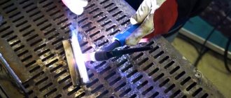
The principle of operation of the tool comes down to several main stages:
- Cleaning the damaged area of paint, putty, primer residues, etc.
- Welding special fastener parts to the deformed area.
- An inertial hammer is hooked onto the clamp, and the metal is leveled with it.
A useful property of the device is the ability to warm up the part. In the process of heating and cooling, shape and rigidity are restored faster and more effectively.
Sometimes, when the need arises to perform urgent welding work, the master cannot do without a special apparatus
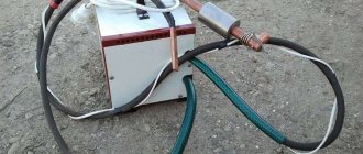
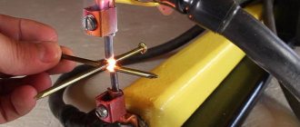
Welding gun
To make a welding handle, no drawings are required. The body of a glue gun is best suited for this purpose. You will also need a copper rod with a diameter of about 20 mm.
On one side of the rod it is necessary to cut a thread (M14x1.5). Various welding attachments will be screwed onto it. A hole is drilled on the other side and an internal M8 thread is cut. The cable will be attached to this place. Also, several grooves should be made on the part so that it is better fixed inside the body.
Next, the part is installed in the housing.
All that remains is to find a suitable button, place it in the case and connect it to the electrical circuit of the device.
How does the spotter work?
The device uses an inverter, but also uses a battery and a transformer for the spotter. The tool is based on the principle of operation of a hammer, it acts on one point, the only difference is the reverse direction of the effect.
Standard example of work:
- a reverse hammer is a guide and a weight on it, which is attached to the deformed area;
- the heavy washer moves along the guide in the direction opposite to the dent. The tool ensures that the metal is straightened point by point.
A standard electric straightening device can operate in two modes:
- short-lived. The guide is fixed in the desired location using rings;
- welding. For welding, the installation is switched to minimum power settings and a carbon electrode is inserted.
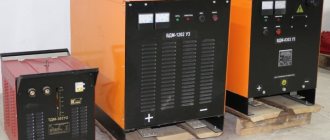
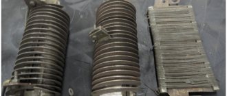
Core types
DIY spot welding for batteries
The cores used in welding transformers can have several different designs (picture below).
Core types
Among them, the following types of CT stand out:
- With the so-called “W-shaped” or armored core;
- With a rod base (in the shape of the letter “O”);
- And finally, with a core made in the form of a torus.
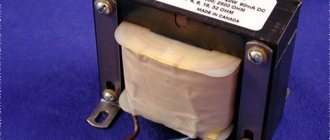
Of all the listed options, the most suitable for the purposes under consideration is a transformer with a toroidal core, which has small dimensions and relatively light weight (see the figure below).
Toroidal transformer
Additional Information. The cross-section of such a core in any transformer will be determined by the expected welding current.
For do-it-yourself spot welding to work properly, the output current of the unit must be at least 1000 Amperes. The latter means that a sufficiently thick wire must be used in the CT output winding. This requirement is fully satisfied by the selected version of the toroidal core, since there is plenty of space for placing the output winding in it.
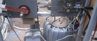
DIY spotter based on inverters
There are a number of schemes according to which a homemade spotter is made. A spotter made from a welding machine with your own hands is the most famous and easiest to implement method of making an installation. A drawing of an inverter spotter is distributed online in various modifications; its popularity is due to the high power of the installation.
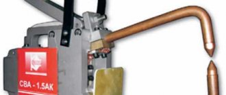
Assemble a spotter with your own hands from a welding machine
The device is classified as a type of resistance welding; pliers are not required for use. According to this parameter, the spotter is comparable to electric arc welding, where the current passes through the body of the car. The “minus” terminal is fixed on the body, and the nozzle and rod will be used as the “plus” contact.
Automatic transmission "Jatco"
The Jatco JF414E transverse automatic transmission belongs to the Mini class. Designed for front-wheel drive vehicles with an engine displacement of no more than 1.6 liters. It was created and developed in the country of Japan, and the company that manufactured this transmission is called “Jatco”. The name is an abbreviation for “Japanese Automatic Transmission Co.”, which translated into Russian means “Japanese Automatic Transmission Plant.”
The JF414E model is not just a set of letters. It also has its meaning.
- “f” means front-wheel drive;
- the number “4” indicates 4 gear stages;
- “14” is the serial number of the modification;
- “e” - electronically controlled.
Inverter spotter circuit
A homemade do-it-yourself spotter, which is assembled from a semi-automatic machine, requires the use of two main spare parts:
- thyristor relay;
- welding inverter.
It’s easy to assemble the simplest spotter with your own hands if you have:
- transformer, it is designed to reduce the voltage to 12 V, it must be installed to control the relay via a button;
- thyristor 200 V;
- relay 30 A;
- diode bridge;
- contact switch for 220 V;
- buttons for adjusting operation.
A bridge of diodes is connected to the network before the transformer. A thyristor from a relay is connected to the bridge. The transformer installation is useful for powering the control branch in the thyristor circuit.
Inverter spotter circuit
A do-it-yourself spotter from a semi-automatic machine has the following scheme:
- When the control button S3 is pressed, the discharge of capacitor C1 is activated, resistor R1 is briefly activated along with thyristor V9.
- Voltage is supplied to the transformer winding through the D232 diode block.
- The body welding process starts using an electrode.
- When capacitor C1 loses charge, the thyristor closes and the voltage from the transformer is redirected.
- After de-energizing the winding, the welding process is completed, now capacitor C1 goes into energy storage mode from transformer T1.
If, before making a spotter with your own hands, you were unable to find a diode bridge and a thyristor, it is possible to replace them with triacs.
For high-quality operation of a machine-based spotter, it is important to carefully consider the design and layout of the device. Even cheap devices must meet minimum installation requirements.
What kind of cookware can an induction cooker see?
Cookware that meets the following requirements is suitable for induction cookers:
- effective energy consumption from the vortex field. This parameter is determined primarily by the material. Not all materials are compatible with induction cooktops. The best option is steel;
- The bottom fits too tightly to the work surface.
It is recommended to use stainless steel containers. Cast iron options and other magnetic alloys are also suitable. In addition to the material of manufacture, the following characteristics of the cookware should be taken into account:
- bottom thickness. It is advisable to use containers with a bottom thickness of 3 mm or more;
- minimum container diameter 12 cm;
- flat and smooth outer side of the bottom. If the bottom is not polished well, the efficiency of the hob will decrease.
Materials
A spotter from a welding machine will require materials and tools to create the installation. Sheet iron 35-40 cm2 is required, since it will not be possible to make a spotter without it due to the risk of overheating. The temperature on homemade equipment increases only in places after the cable; additionally strong heating occurs on the iron rod with a diameter of 16 mm. To reduce the temperature at the stem, it is preferable to use brass.
The welding transformer for spotter, designed for spot work, is somewhat different from the classic design
The characteristics of the power cable are determined depending on the power of the spotter, but it is preferable to choose 70 mm2 or more. It is better to take a wire for ground 1.7 m long, and for connecting a hammer - 2.1 m. It is advisable to equip a spotter with your own hands from a battery with control using pulses through a thyristor ТЧ-40.
Initially, the outer winding of the transformer is applied using a copper busbar with dimensions 6, 5, 4 on the 3rd layer of the winding. When using a battery, it is permissible to replace the wire with an aluminum one. An additional two are applied to the second winding. At the end of the work, the battery-based equipment should be made of aluminum or copper with an area of 250 mm2 (5 windings of 6 turns each).
It is important to pay attention not only to the functionality of the installation, but also to ease of use. The design of the inertial hammer creates conditions for safe and easy use of the device. The glue gun spare part is mainly used.
A layer of thermal insulation and a wire for switching must be applied to the power cable. Thermal insulation should be applied with reserve, since when heated it shrinks and the area may be exposed.
Secondary winding
Selecting parameters
When remaking a CT, the main attention should be paid to the parameters of the secondary winding, which determine the output characteristics of the device (its load current, in particular)
In this case, it is important to select a bus cross-section that would provide a current density of about 8 A/mm² (with a cross-sectional area of about 120 mm²). Since it is very difficult to handle such a thick busbar when winding on a torus, they are most often limited to a value of 80 mm²
Since it is very difficult to handle such a thick busbar when winding on a torus, they are most often limited to a value of 80 mm².
Note! The specified cross-section can be obtained by putting together several wires of slightly less thickness. To facilitate the conditions for converting a CT into a point unit, it is advisable to pre-calculate the amount of wire required for rewinding it
After this, it will be possible (based on the space occupied by the winding) to determine whether it will fit into the free space remaining on the torus or not
To facilitate the conditions for converting a CT into a point unit, it is advisable to pre-calculate the amount of wire required for rewinding it. After this, it will be possible (based on the space occupied by the winding) to decide whether it will fit into the free space remaining on the torus or not.
Important! In the case where the new winding does not fit into the torus, the old secondary coil will have to be completely disassembled (dismantled). For ease of handling of new wires during the winding process, it is recommended to wrap them with fabric-based insulating tape
To determine the exact number of turns that affect the output voltage, we recommend using the test winding method with a small-section wire in insulation
To make it easier to handle new wires during the winding process, it is recommended to wrap them with fabric-based insulating tape. To determine the exact number of turns that affect the output voltage, we recommend using the test winding method with a small-section wire in insulation.
Since the winding in this case is not connected to the load, the cross-section of the test wire is not very important. Experience has shown that during rough tests it is sufficient to use no more than 10 turns. After winding them, the transformer should be connected to the network and the voltage produced by the test coil should be measured, after which it is divided by the number of turns. The result is a figure indicating the number of turns required to produce one volt of output.
Since in this case it is necessary to obtain 6 Volts, multiplying the number obtained from the test connection by 6, we obtain the required number of turns.
In order to make a new device with your own hands, you must first calculate the amount of wire required for rewinding the CT. After this, it will be possible (based on the space occupied by the bus winding) to determine whether it will fit into the free space remaining on the torus.
Winding diagrams and placement
The connection diagram and the order of placement of the “secondary” depend on the type of core selected. Given the toroidal base of the CT that we have declared, it is more convenient to divide it into two half windings connected in series (3 Volts each).
In order to increase the load capacity (increase the welding current), you can make two windings of 6 Volts each and connect them in parallel. In this case, the output voltage will not change, and the load current can be doubled. This design option allows us to solve the problem of the large cross-section of the secondary bus, which can then be reduced by half.
Various types of connections of such windings are shown in the picture below.
Secondary connection circuits
The order in which they are connected is very important to obtain the required output parameters, and mistakes made in this case can lead to completely different indicators. So, in particular, if you make a mistake during installation and turn on two windings in opposite directions, as a result they will be short-circuited to one another and will produce zero voltage at the output, which is equivalent to a short circuit.
At the ends of ready-made secondary windings, special tips should be equipped by crimping.
Key functions and technical characteristics of the spotter
Regardless of the type of device: factory (used in industry) or homemade design, they have the same functions:
- welding of body elements using repair washers;
- spot welding with a metal electrode. The pin is selected to be strong so that it can be used to pull out the body;
- the ability to heat body parts using a carbon-type electrode and sharply cool the base. This function helps create metal precipitation;
- Due to two operating modes, the efficiency and ease of use of the device is improved. When the first mode is activated, stable operation occurs; it is intended for use with a carbon electrode. The second mode involves short-term activation, the activity time is set manually. Used together with an iron electrode, often used to install washers;
Spot welding spotters must be limited by the time the part is welded
The device has a built-in cooling system and a thermostat for deactivation in case of strong heating. Switching off and on is performed automatically when the set marks are reached.
Basic characteristics of spotters:
- voltage in the power supply network for proper operation of the installation is 220 V (sometimes 380 V);
- AC frequency – from 50 to 60 Hz;
- maximum power of the device – 10 kW;
- current at maximum load – 1300 A;
- voltage in the 2nd layer of the welding machine winding is 8-9V;
- activity time range – from 0 to 1.2 s;
- 2 operating modes: with timer switching on (for spot welding) and continuous operation in standard mode and tempering;
- productivity when setting the spot welding mode in relation to the maximum output power - 15%;
- productivity in the case of using coal welding in relation to the maximum output power - 75%;
- needle breaking force – over 100 kg;
- traction force on the washer – over 100 kg;
- design dimensions – 380x290x840 mm;
- weight – 32 kg.
Important nuances in the design
The greatest difficulty in adapting a transformer lies in increasing the output current. To do this, they experiment with a bus, which is installed instead of the secondary winding. Experience makes it clear that the cross-sectional indicator should be at least 160 square meters. mm. As for the bus voltage, it should not be less than 6 volts. The most important point when assembling a transformer is maintaining optimal insulation of the network windings. If the overlay was done incorrectly, it will lead to undesirable consequences.
How to weld parts using a spotter?
Today, a unified technology for using the installation has been developed, which is used by all professional straighteners. Most often, the technique is appropriate for working with deformed parts located in hard-to-reach places. This type of welding is used for straightening damaged wings, doors, and pillars. The spotter is useful for correcting any surface that requires leveling efforts in the opposite direction.
Resistance welding requires a short voltage pulse
Spot welding uses transmitted current to create adhesion to the part. Next, a stop or an inertial hammer is attached to the area. The listed manipulations ensure quick and high-quality restoration of the body.
After bringing the body element to its original state, the hook is removed and the surface is cleaned. Grinding is necessary due to the presence of metal residue from welding on the body, otherwise it will not be possible to install a smooth surface.
Spotter technology:
- The damaged area of the part is cleaned of all coating; high-quality contact with the metal must be created.
- A grounding contact is connected to the cleaned area.
- Weld fasteners for holding tools.
- Using metal leveling tools, they engage the retainer.
- The area is pulled out until the original condition is restored or close to it.
- The attached hook is torn off manually in a circular motion.
- Clean the surface until it is smooth and prepare it for puttying and painting.
A spotter is similar in type to a welding machine; to use it, it is advisable to have basic welding skills. During the manipulation process, it is imperative to follow the rules of operation and personal protection. The device is useful for all types of restoration work on the car body, where a targeted impact is required.
Examination
Before use, you must first check the equipment for operational safety. To do this, a preventive examination is carried out:
- clean all elements;
- check the correct insulation of the wires;
- clean the deformed surface;
- inspect the reliability of fastening of all parts;
- ground the device.
Only after carrying out the above steps, you can start using the unit.
Expert advice
Masters with experience in performing body work recommend:
- Monitoring the case grounding is a mandatory safety measure. The negative terminal should be disconnected from the battery;
- supplement the spotter circuit with auxiliary circuit elements to prevent overload and increase power;
- If you want to straighten the power elements of a car with a device, give the choice to more powerful devices. They install a steel rod instead of an electrode.
It’s not difficult to create a spotter yourself if you have all the materials and time; it’s just important to think about the location and type of circuit elements. The simplest device allows you to straighten a car in the garage, but in production it will not be enough.
Manufacturing or selection of a supply transformer
If it is difficult to find a ready-made device with the required voltage, then you can make it yourself. The voltage must correspond to the required value - up to 1500 A. For this, a magnetic core with a length not exceeding 400 mm² is selected. Dimensions are calculated taking into account the distribution of the winding.
The W-shaped core must have a primary winding (200 turns) of wire with a cross-section of 2.5 mm² and the ability to connect the ends to an electrical circuit. Secondary (7 turns) – 50 mm², including connection to terminals.
The secondary winding is carefully removed using a chisel or chisel. Damage to the primary winding insulation must be avoided. Then a cable of seven turns is wound, with a cross-section of 50 mm². If you have a wire with a smaller cross-section (30 mm²), the number of turns on the secondary winding will need to be increased (up to 10).
A semi-automatic device (the above steps are carried out), as well as an inverter, are suitable as power supply equipment. The tension strength of the latter is the best choice. To do this, the transformer assembly is placed in the circuit in place of T2, and other elements are assembled taking into account the parameters of the circuit.