TL431 is an adjustable parallel voltage regulator. Otherwise, it can be called a “controlled programmable zener diode”. It is intended for use as a reference voltage block in various variations of power supply circuits, and can also serve as a substitute for Zener diodes in various circuits. Despite the considerable age of the microcircuit - almost 50 years - it remains popular today. All thanks to its size, stability and ease of connection. It has good characteristics that allow it to be used on both a hobby and industrial scale. Among other things, another advantage of this chip is the low noise level at its output.
The TL431 was first introduced to the world by Texas Instruments back in 1977. Over all this time, the technical production process has been significantly improved, and therefore the accuracy of the characteristics in comparison with those indicated in the datasheet. Since then, this chip has become an integral part of a large variety of manufactured switching power supplies.
TL431 circuit
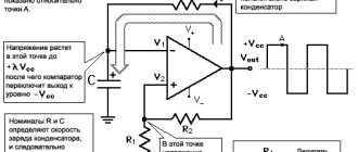
Let's consider the circuit, which is in the official datasheet of the manufacturer Texas Instruments.
The scheme is quite simple. It shows a very ordinary operational amplifier (looks like a triangle in the picture), which is connected to a transistor at the output.
How does TL431 work?
Everything here is elementary. The input to the operational amplifier is a 2.5V reference voltage source, which is connected to the input. The pin, code-named REF, and the collector and emitter of the transistor are connected to the power supply pins of the amplifier. And safety is ensured by a protective diode, which will preserve and protect the microcircuit from polarity reversal.
In order for the output transistor to open, you need to apply a signal to the REF input, the voltage of which will be slightly greater than the reference one. Since an excess of a couple of millivolts is enough, we can safely assume that we are supplying a voltage that is equal to the reference one. In this case, the output from the op-amp sends voltage to the base of the transistor, and it opens.
It turns out that this microcircuit is like a field-effect transistor. It continuously compares the input voltage with the reference voltage, and when the voltage at the input is higher, it opens.
Especially for those who are especially curious, the TL431 datasheet also contains an image of a detailed diagram:
As you can see, even in the expanded diagram shown, the TL431 device does not evoke a feeling of fear.
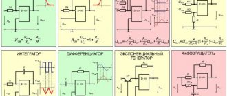
Electrical characteristics graphs
A graphical plot for the various parameters can be seen in the technical description accompanying this electronic element.
Parametric Process Graphs
The use of a controlled zener diode in the construction of electronic circuits does not cause any particular difficulties. Low cost and availability make the TL431 IC a widely used microcircuit. When dismantling and installing on finished boards, you can focus on the designations of the names of the pins, which are applied to the surface of the board.
Types of TL431
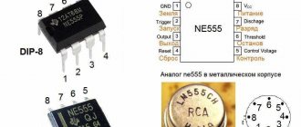
The TL431 is produced in various housing variations. Depending on the type of installation, you can choose the one that suits your project. For through-hole and surface mounting: TO-92, and for surface mounting: SOT-23, SOT-25, SOT-89 and SOP-8.
For prototyping and simple homemade projects without using printed circuit boards, the TO92 is the most convenient option, since it can be used both in conjunction with a breadboard and with surface mounting.
TL431 connection
Regardless of the type of case, the microcircuit has 3 contacts. And in cases with a large number of legs, the remainder is not used or duplicates the main 3. Here you can see the pinout of all TL431 variants.
The minimum connection diagram consists of only one resistor. At the output of this circuit, the voltage will be equal to the reference - 2.5V.
For car inverters
For automotive inverters, AC zener diodes TL431 are often used. The connection circuit in this case involves the use of two-digit triodes. The filters themselves are used in the open type. If we consider circuits without an expander, the threshold voltage fluctuates around 10 W.
The direct operating current is 4 A. The system overload parameter is allowed at 3 mA. If we consider modifications with expanders, then in this case high-capacity modulators are installed. Resistors are used as standard selective type.
In some cases, amplifiers of different power are used. The threshold voltage parameter, as a rule, does not exceed 12 W. The output impedance of the system can range from 70 to 80 ohms. The stabilization accuracy rate is approximately 2%. The operating current of the systems is no more than 4.5 A. The zener diodes are directly connected through the cathode.
Circuits using TL431
The chip can be used in many different power supply designs. These can be either regulated power supplies or battery chargers. Let's look at a few basic, typical schemes that can be modernized, and on the basis of which you can create your own ideas and creations.
Voltage stabilizer on TL431 (2.5-36V, 100mA)
This circuit allows you to replace an ordinary zener diode. You can change the output voltage by changing the resistance of resistors R1 and R2. To calculate the resistance, we recommend using the formula below:
Voltage stabilizer with increased maximum current (2.5-36V)
The maximum output current of the TL431 is 100mA. However, if your project requires a higher output current, then we advise you to use a transistor: then the maximum current will depend on its characteristics. The formula for calculating resistor resistance remains the same.
Similar circuits are often used with other ICs. Unfortunately, most of them simply cannot pass high current, so to solve this problem, a control transistor comes into play. In this case, the maximum current is limited by its properties. The main task here is the correct selection of the transistor for the control voltage at its base.
Laboratory power supply on TL431 with protection
This circuit is an adjustable power supply that is capable of delivering up to 30W. And besides this, it has built-in overload protection. If the current begins to exceed the permissible value on transistor T2, then the voltage supply to the LBP will stop, which will be signaled by a lit LED.
Do not forget to use cooling in the form of a radiator, because components will quickly heat up during peak loads, and over time, with frequent overheating, they will fail.
Current stabilizer on TL431 (LED driver)
Most often, current stabilizers are used to power LEDs and LED strips. The circuit here is elementary - you only need a couple of resistors and one transistor.
Voltage indicator
The circuit may be needed when you need to ensure that the voltage does not go beyond the upper and lower limits. These limits are set by the resistance of the resistors, according to the formula given below.
This circuit can be upgraded by adding tweeters or other sound devices. This way you will definitely not be able to miss a signal about an incorrect voltage.
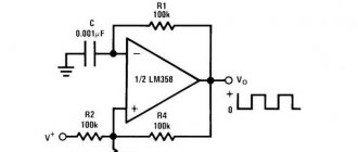
Delay timer on TL431
A universal microcircuit on which it is possible to implement even a delay timer circuit. All you need is a couple of resistors and a capacitor. Their values must be calculated using the formula to obtain the required delay time (the formula is given below).
This circuit is possible due to the very low input current (4 μA). When the main contact closes, the transistor begins to charge. After reaching 2.5V, it opens, and current, assisted by an optocoupler LED (optocoupler), begins to flow, causing a short circuit in the external circuit.
Charger for lithium batteries on TL431 and LM317
This simplest circuit allows you to properly charge lithium batteries. This charging uses TL431 as the voltage reference and LM317 as the current source. The device charges batteries using the CC CV method, which means, as everyone knows, Constant Current, Constant Voltage.
The input voltage for this circuit is 9-20V. First, the battery is charged with a constant current, which can be changed by changing the resistance of resistor R5. After the battery reaches a voltage of about 4.2V, it begins to charge with constant voltage.
Please note that it is very important to configure the device before use: without load, you need to adjust the variable resistor RV1 so that the output voltage is 4.2 Volts.
Specifications
How to test a zener diode with a multimeter
The tl431a IC, the description of which explains its operation, has the following parameters:
- Uin interval – from 2.5 to 36V;
- Rout – 0.2 Ohm;
- permissible current in the forward direction – from 1 to 100 mA;
- error bar (%) – 0.5%, 1%, 2%.
The microassembly does not contain lead, is thermally stable over the entire operating temperature range and has a low output noise level.
LT431 Electrical Specifications
Accuracy characteristics
Current stabilizers tl431 have the accuracy of the characteristics declared according to the manufacturer's passport. The main parameter is UREF=2.495 V. It was determined under the following conditions:
- at a current through the cathode of 10 mA;
- at T avg. = +250С;
- in the mode of closing input R to cathode K.
The actual value of UREF in a particular scheme may depend on several reasons:
- variable temperature deviations;
- influence of voltage UAK (between anode and cathode);
- influence of IK (cathode current) on the steepness of transformations.
In any case, the deviation of the UREF value is no more than 20-40 mV.
Frequency characteristics
The frequency response (amplitude-frequency response) of the tl431 zener diode can be described by a simple model that includes an ideal voltage-to-current converter. At its output, a capacitance C = 70 nF acts as a shunt. When the stabilizer operates on a load with a resistance Rн = 230 Ohms, the frequency response has a decline starting at 10 kHz.
For your information. If we calculate the amplification frequency without taking into account Rn, then it is approximately 2 MHz. However, the decrease in frequency response at higher frequencies occurs faster than the calculated one and amounts to 1 MHz. Such features do not affect the performance of the IS and may not be taken into account.
How to check TL431
Since this is not a single radio component, but a whole circuit enclosed in a small package, we cannot test it with just a multimeter, because it only contains 10 transistors, not to mention the other components. Checking the resistance between the pins will not provide any useful information, since reference values vary from batch to batch and from manufacturer to manufacturer.
Therefore, as with testing most microcircuits, it is necessary to assemble a simple circuit using it. The following diagram could serve as such:
When 12V is supplied to the input, the output should be 5V, and when S1 is closed, the reference voltage of the TL431 microcircuit should go to the output - 2.5V. You can choose your own values. It is important that they comply with the formula:
If all the values are correct, then the chip is working and can be used in the project. If you assemble a small stand with such a circuit on a breadboard, you will be able to test a large number of TL431 and similar microcircuits in a pipeline.
compensation voltage stabilizer
The principle of the compensation stabilizer on the TL431 is the same as on a conventional zener diode: the voltage difference between the input and output is compensated by a powerful bipolar transistor. But the accuracy of stabilization is higher due to the fact that feedback is taken from the output of the stabilizer. Resistor R1 must be calculated for a minimum current of 5 mA, R2 and R3 are calculated in the same way as for a parametric stabilizer.
To stabilize currents at the level of units and tens of Amperes, one transistor in a compensation stabilizer is not enough; an intermediate amplifier stage is needed. Both transistors operate according to an emitter follower circuit, i.e. The current increases, but the voltage does not increase. The figure shows a real circuit of the compensating stabilizer on the TL431; new components have appeared in it: resistor R2 limits the base current of VT1 (for example, 330 Ohms), resistor R3 compensates the reverse collector current of VT2 (which is especially important when heating VT2) (for example, 4.7 kOhm ) and capacitor C1 - increasing the stability of the stabilizer at high frequencies (for example, 0.01 µF).
Application of TL431
This chip can be used in various power devices of varying power. TL431 is used in the production of power supplies, LBPs, voltage and current stabilizers, and other things.
This chip can serve as a conventional comparator, but thanks to the internal reference power supply, circuits using the TL431 in this way are greatly simplified. In this case, you can use it to create a circuit for a thermostat and other devices for reading signals from analog sensors. It can also serve as a voltage indicator. Including sound.
But most often it is used as a reference power source in conjunction with other microcircuits, since it produces it very stably. There are many circuits where the TL431 is used in conjunction with the LM317, another popular adjustable stabilizer.
AC models
Cherry AC zener diodes TL431 are often used for dipole inverters. How to check the functionality of the connected element? This can be done using a regular tester. The output resistance parameter must be no more than 70 Ohms
It is also important to note that devices in this series are switched on via a vector converter
In this case, scalar modifications are not suitable. This is largely due to the low threshold of current conduction
It is also important to note that the nominal voltage does not exceed 4 W. The operating current in the circuit is maintained at 2 A
To reduce heat losses, various thyristors are used. Today, expansion and phase modifications are produced.
Analogs TL431
Since the microcircuit has gained great popularity, it is now not difficult to find its analogues. If you are looking for analogues from domestic manufacturers, then here is a list for you:
- KR142EN19
- KR142EN19A
- K1156ER5T
The most complete analogues are:
- IR943N
- TL432
- LM431
You can also use the following to replace Tl431:
- KA431AZ
- KIA431
- HA17431VP
- IR9431N
- AME431BxxxxBZ
- AS431A1D
- LM431BCM
- HA17431A, KIA431
- APL1431
For most of these options, the scheme will not need to be changed. But it’s worth checking the datasheet of each of them to be sure that the pinout is the same as the TL431.
Safe Operation of the TL431
During operation, it is necessary to comply with the environmental parameters described by the manufacturer. This is necessary not only for longer component life, but also for predictable behavior. The table below shows the performance of the TL431 at 25°C.
The element must not be overloaded; its maximum input voltage is 36V.
It is best that the load current is at least 5mA, otherwise the microcircuit may operate unstable and unpredictably.
TL 431 integrated zener diode
Key Features of the TL 431 Programmable Voltage Reference
- Rated operating voltage at the output is from 2.5 to 36 V;
- Output current up to 100 mA;
- Power 0.2 Watt;
- Operating temperature range for TL 431C from 0° to 70°;
- The operating temperature range for TL 431A is from -40° to +85°.
The accuracy of the TL 431 integrated circuit is indicated by the sixth letter in the designation:
- Accuracy without a letter – 2%;
- Letter A – 1%;
- Letter B – 0.5%.
Its widespread use is due to its low price, universal form factor, reliability, and good resistance to aggressive environmental factors. But it should also be noted the accuracy of this voltage regulator. This allowed him to occupy a niche in microelectronics devices.
The main purpose of the TL 431 is to stabilize the reference voltage in the circuit. Provided that the voltage at the source input is below the rated reference voltage, the transistor in the programmable module will be closed and the current passing between the cathode and anode will not exceed 1 mA. If the output voltage exceeds the programmed level, the transistor will be open and electric current will be able to freely pass from the cathode to the anode.
Wiring diagram TL 431
Depending on the operating voltage of the device, the connection circuit will consist of a single-stage converter and expander (for 2.48 V devices) or a small capacity modulator (for 3.3 V devices). And also to reduce the risk of a short circuit, a fuse is installed in the circuit, usually behind the zener diode. The physical connection is influenced by the form factor of the device in which the TL 431 circuit will be located, and environmental conditions (mainly temperature).
Stabilizer based on TL 431
The simplest stabilizer based on the TL 431 is a parametric stabilizer. To do this, you need to include two resistors R 1, R 2 in the circuit through which you can set the output voltage for TL 431 using the formula: U out = Vref (1 + R 1/ R 2). As can be seen from the formula here, the output voltage will be directly proportional to the ratio of R 1 to R 2. The integrated circuit will keep the voltage at 2.5 V. For resistor R 1, the output value is calculated as follows: R 1 = R 2 (U out / Vref - 1).
This regulator circuit is typically used in fixed or variable voltage power supplies. Such voltage stabilizers on the TL 431 can be found in printers, plotters, and industrial power supplies. If it is necessary to calculate the voltage for fixed power supplies, then we use the formula Vo = (1 + R 1/ R 2) Vref.
Timing relay
The precision characteristics of the TL 431 allow it to be used for other than its intended purpose. Due to the fact that the input current of this adjustable stabilizer is from 2 to 4 μA, a temporary relay can be assembled using this chip. The role of a timer in it will be played by R1, which will begin to gradually charge after opening the contacts S 1 C 1. When the voltage at the output of the stabilizer reaches 2.5 V, transistor DA1 will be open, current will begin to flow through the LEDs of the PC 817 optocoupler, and the open photoresistor will close the circuit.
Thermal stabilizer based on TL 431
The technical characteristics of TL 431 make it possible to create thermally stable current stabilizers based on it. In which resistor R2 acts as a feedback shunt, a value of 2.5 V is constantly maintained on it. As a result, the value of the load current will be calculated using the formula In = 2.5/R2.
Pinout and serviceability check of TL 431
The TL 431 form factor and its pinout will depend on the manufacturer. There are options in old TO-92 and new SOT-23 packages. Don’t forget about the domestic analogue: KR142EN19A is also widespread on the market. In most cases, the pinout is applied directly to the board. However, not all manufacturers do this, and in some cases you will have to look for information on pins in the data sheet of a particular device.
TL 431 is an integrated circuit and consists of 10 transistors. Because of this, it is impossible to check it with a multimeter. To check the serviceability of the TL 431 chip, you need to use a test circuit. Of course, there is often no point in looking for a burnt-out element and it is easier to replace the entire circuit.
Calculation programs for TL 431
There are many sites on the Internet where you can download calculator programs to calculate voltage and current parameters. They can indicate the types of resistors, capacitors, microcircuits and other components of the circuit. TL 431 calculators are also available online; they are not as functional as installed programs, but if you only need the input/output and maximum values of the circuit, then they will cope with this task.
Manufacturers TL431
Due to its incredible popularity, the TL431 is produced by almost all of the largest enterprises that specialize in the production of microcircuits. However, not all of them are sold in the CIS; many are sold only abroad. Among those companies whose products come to us:
- Texas Instruments
- ONS
- STM
- Nexperia
- HTC
- NXP Semiconductors
Other manufacturers of these products whose products are not available from us: Hotchip Technology, Calogic, Motorola, HIKE Electronics, Fairchild Semiconductor.