The 78L05 low-power positive polarity stabilizer is designed for use in DC power supplies. In addition, it can be used with power elements to make voltage regulators.
They have built-in protection against overcurrent and voltage, which makes them very reliable. If an appropriate heatsink is provided, they can provide an output current of up to 100 mA. Due to its low cost and ease of use, it has gained great popularity.
Operating principle of the element
From the outside and the type of pn junction, the device is very similar to a semiconductor diode. If you look at the schematic designation, there are no significant differences either.
The current flowing through the device has only one direction, but there are some nuances here. The diode promotes the movement of microparticles only according to the anode-cathode principle. If the opposite direction is given, this is already a critical unacceptable situation. Namely, it means a breakdown of the radio component.
For a zener diode, the reverse movement of current is the norm, or rather, its special task. When a certain voltage appears at the terminals, electrons begin to move in the cathode-anode direction. This results in a reverse-conducting element.
Voltage is the main parameter here. For example, if a zener diode has 12 V, the current flows in the opposite direction.
Let's give the most basic example. Let's say we have a water container with a certain location of the drain pipe.
When water reaches a certain level, it overflows from the drain pipe. More specifically, the container is filled only to a limited level. It persists at least until the pressure changes. If the liquid exceeds the drainage capacity of the pipe, the vessel may burst or overflow.
Now let's make an electronic analogy.
Instead of liquid pressure, we have the maximum current that a zener diode can have. There are no temperature damage here. And instead of the possible water level, we consider the voltage at which the zener diode can operate.
When the specified voltage is reached, it is maintained and the remaining current is sent back. It turns out that the device makes the voltage constant. Therefore, if the current is too high, the stabilizer may burn out.
The main task for determining the performance of the device is to understand what the stabilization voltage is on the zener diode.
Thus, the device in question is a part that maintains a constant voltage at its contacts. In this case, the voltage at the source should greatly exceed this figure directly at the zener diode. The current limits the resistance, and its value is always significantly less than the maximum possible power.
Marking 78L05
Designations contain a minimum amount of information about the characteristics of the device. The number 78 indicates polarity with a “+” sign, the letter L indicates a low current strength of no more than 0.1 A, and the numbers 05 indicate load voltage up to 5 V. The symbols located at the end show the level of stabilization accuracy, the temperature range acceptable for operation, body type.
Today, other companies have begun producing full-fledged copies of the 78L05. For example, a device with the same designations is manufactured by the Chinese manufacturer Wing Shing Computer Components (WS). There are others:
- Texas Instruments;
- Fairchild (LM78L05);
- STMicroelectronics (L78L05).
The second option is popular on the Russian market, which we will talk about.
Description of stabilizer 78L05
This stabilizer is not expensive () and is easy to use, which makes it easier to design radio-electronic circuits with a significant number of printed circuit boards to which an unstabilized DC voltage is supplied, and each board has its own stabilizer mounted separately.
The 78L05 (7805) stabilizer chip has thermal protection, as well as a built-in system that protects the stabilizer from overcurrent. However, for more reliable operation, it is advisable to use a diode to protect the stabilizer from a short circuit in the input circuit.
The only difference is the polarity of the output voltages. An adjustable voltage stabilizer is a type of regulator whose adjustable output voltage can vary within a range. There are two variations of the same thing; known as positive regulated voltage regulator and negative regulated voltage regulator.
There may be certain conditions where AC voltage may be required. The connection diagram is shown below. The required output voltage can be calculated using Eq. So the above equation can be rewritten as. Load regulation is 1 percent and linear regulation is 01% per volt. This means that the output voltage only changes by 01% for each input voltage voltage. The ripple hole is 80 dB, which is equivalent to 10.
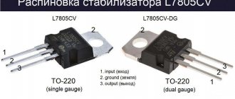
Pinout 78L05
First of all, you need to know the pinout option of the smd type with 8 legs. But the standard version of this chip with a TO-92 package has only 3 pins (input, ground, output). The number of pins is quite normal, considering that some of them are not connected to anything or are connected to each other by electrical wires inside a plastic package.
For a better understanding of the pinout, take a look at the figure. It shows that it is not the same for all manufacturers.
Stabilizers from WS have a mirror pinout, which does not correspond to options from other companies. But Chinese manufacturers, on the contrary, adhere to WS standards. Always keep this point in mind, as it often causes the system to fail.
Manufacturers and datasheet
Below is a datasheet for 78L05 from the most common foreign companies. We list the ten largest of them:
- Texas Instruments;
- Microdiode Electronics (Jiangsu);
- ON Semiconductor;
- Guangdong Kexin Industrial;
- Continental Device India Limited;
- SEMTECH ELECTRONICS;
- STMicroelectronics;
- Nanjing International Group;
- GUANGDONG HOTTECH INDUSTRIAL;
- KIA Semiconductor Technology.
In domestic stores you can find most of their presented manufacturers.
Parameters allowed for operation
As a rule, the main task of the stabilizer in WS circuits is to constantly regulate the voltage so that it does not deviate from the 5 V level. To maintain its stable operation, it is necessary to supply a voltage 2-3 V higher than the output. With good heat dissipation, the device can withstand an output current of 100 A.
Maximum values
The microcircuit has several maximums allowed for operation:
- Input voltage - 30 V.
- Output current - 0.1 A.
- The heating temperature of the crystal is 125 degrees.
- Storage conditions: from -65 to 150 degrees.
- The dissipated power is controlled internally by the protection.
Thanks to constructive protection, the device will not overheat and short-circuit.
Permissible electrical characteristics
In the table you can see the electrical parameters for a typical test circuit. One of the columns shows the operating conditions of the device at no more than 25 degrees. Its limits are determined by the modification of the device. The given characteristics are often found in the L78L05 chip lines.
A typical test circuit contains capacitors with a capacity of 0.33 and 0.1 μF. It is supplied with a zero voltage of 10 V. Unless otherwise specified, the output current is 40 mA.
All the given data shows that all L78L05 are different in a number of values. You need to take a closer look at individual modification features. For example, if the designation of a device contains the letter B, this indicates its ability to function at low temperatures, up to -40 degrees. But the letter “A” at the end of the name is a sign of high accuracy in stabilizing the output voltage up to 4%. The symbol “C” indicates that for standard stabilizers this range is doubled.
There is nothing complicated in the classic circuit for switching on the device, in which testing is carried out. To create it you do not need to be a professional radio engineer or electronics engineer. It contains both the microcircuit itself and 2 smoothing capacitors. The input capacitance is always much higher than the output capacitance, since it suppresses external fluctuations from the electrical source. The output capacitance, in turn, is needed to suppress high-frequency ripples.
Smoothing capacitors, according to the manufacturer’s advice, are soldered close to the legs to reduce the level of interference and stability of operation.
DataSheet
Peculiarities
- LM78L05 in DSBGA package
- Voltage deviation in temperature range - ±5%
- Output current 100 mA
- Internal thermal protection
- Output transistor in safe area
- Internal short circuit protection
- Available in TO-92 and SOIC-8 packages
- No external components
- Output voltage - 5 V, 6.2 V, 8.2 V, 9.0 V, 12 V, 15 V
Description
The LM78LXX series stabilizers are available in versions with several fixed output voltages. Using a zener diode/resistor as a replacement improves the effective output impedance by a factor of two and reduces current consumption. The LM78LXX can be used in digital systems, HiFi equipment and other solid state electronic equipment. LM78LXX are available in TO-92 (LP), SOIC-8 (D), DSBGA packages. In the operating temperature range, the stabilizers support an output current of up to 100 mA. A protection zone for the output transistors ensures that internal power dissipation is limited. If internal power dissipation becomes too high, thermal protection prevents the IC from overheating.
Pin layout
Rice. 1 SOIC-8 (D) package (top view, narrow case) Fig. 2 DSBGA package (top view) Fig. 3 Pinout for TO-92 (LP) housing (bottom view
Rice. 4 DSBGA package - marking location
Absolute maximum values (1)
| Power dissipation (2) | Internally limited |
| Input voltage | 35 V |
| Storage temperature | from −65°C to +150°C |
| Electrostatic susceptibility (3) | 1 kV |
| Operating temperature range of p-n junction | |
| LM78LxxACZ,TO-92 | from 0°C to 125°C |
| LM78LxxACM,SOIC-8 | from 0°C to 125°C |
| LM78LxxAIM, SOIC-8 | -40°C to 125°C |
| LM78LxxIBPX,DSBGA | -40°C to 85°C |
| LM78LxxITP, Slim DSBGA | -40°C to 85°C |
| Soldering information | |
| Infrared radiation or convection (20 s) | 235°C |
| Wave soldering (10 s) | 260°C (running time) |
(1) Absolute maximum values indicate limits which, if exceeded, may result in damage to the device. Electrical specifications do not apply when the device is operated outside its stated operating conditions.
(2) Thermal resistance for enclosures:
LP case: θJC = 60 °C/W, θJA = 230 °C/W
D housing: θJA = 180 °C/W
DSBGA package: θJA = 230.9 °C/W
(3) Human body model - 1.5 kOhm resistor with 100 pF capacitor.
LM78LXX Electrical data LM78L05AC / LM78L05AI / LM78L05I
The values indicated in standard font are for TJ = 25°C, and in bold font for the entire operating temperature range specified for this type of housing. Limits are ensured through the use of Statistical Quality Control (SQC) method. Unless otherwise noted: IO = 40 mA, CI = 0.33 µF, CO = 0.1 µF, VIN = 10 V.
| Designation | Parameter | Conditions | Min. | Type. | Max. | Unit change |
| V.O. | Output voltage | 4.8 | 5 | 5.2 | IN | |
| 7 V ≤ VIN ≤ 20 V, 1 mA ≤ IO ≤ 40 mA (1) | 4.75 | 5.25 | IN | |||
| 1 mA ≤ IO ≤70 mA (1) | 4.75 | 5.25 | ||||
| ΔVO | Output voltage instability | 7 V ≤ VIN ≤ 20 V | 18 | 75 | mV | |
| 8 V ≤ VIN ≤ 20 V | 10 | 54 | ||||
| ΔVO | Instability of output voltage across load | 1 mA ≤ IO ≤100 mA | 20 | 60 | ||
| 1 mA ≤ IO ≤40 mA | 5 | 30 | ||||
| IQ | Quiescent current | 3 | 5 | mA | ||
| ΔIQ | Quiescent current deviation | 8 V ≤ VIN ≤ 20 V | 1.0 | mA | ||
| 1 mA ≤ IO ≤40 mA | 0.1 | |||||
| Vn | Output noise voltage | f = 10 Hz to 100 kHz (2) | 40 | µV | ||
| ΔVIN/ΔVOUT | Ripple Suppression | f = 120 Hz, 8 V ≤ VIN ≤ 16 V | 47 | 62 | dB | |
| IPK | Peak output current | 140 | mA | |||
| ΔVO/ΔT | Average deviation of output voltage from temperature | IO = 5 mA | −0.65 | mV/°C | ||
| VIN (Min) | Minimum input voltage to maintain line regulation | 6.7 | 7 | IN | ||
| θJA | Thermal resistance | 230.9 | °C/W |
(1) Power dissipation ≤ 0.75W.
(2) The recommended minimum load capacitance to limit high frequency noise is 0.1 µF.
Electrical Specifications LM78L62AC
VIN = 12V unless otherwise noted
| Designation | Parameter | Conditions | Min. | Type. | Max. | Unit change |
| V.O. | Output voltage | 5.95 | 6.2 | 6.45 | IN | |
| 8.5 V ≤ VIN ≤ 20 V, 1 mA ≤ IO ≤ 40 mA (1) | 5.9 | 6.5 | IN | |||
| 1 mA ≤ IO ≤70 mA (1) | 5.9 | 6.5 | ||||
| ΔVO | Output voltage instability | 8.5 V ≤ VIN ≤ 20 V | 65 | 175 | mV | |
| 9 V ≤ VIN ≤ 20 V | 55 | 125 | ||||
| ΔVO | Instability of output voltage across load | 1 mA ≤ IO ≤100 mA | 13 | 80 | ||
| 1 mA ≤ IO ≤40 mA | 6 | 40 | ||||
| IQ | Quiescent current | 2 | 5.5 | mA | ||
| ΔIQ | Quiescent current deviation | 8 V ≤ VIN ≤ 20 V | 1.5 | mA | ||
| 1 mA ≤ IO ≤40 mA | 0.1 | |||||
| Vn | Output noise voltage | f = 10 Hz to 100 kHz (2) | 50 | µV | ||
| ΔVIN/ΔVOUT | Ripple Suppression | f = 120 Hz, 19 V ≤ VIN ≤ 20 V | 40 | 46 | dB | |
| IPK | Peak output current | 140 | mA | |||
| ΔVO/ΔT | Average deviation of output voltage from temperature | IO = 5 mA | −0.75 | mV/°C | ||
| VIN (Min) | Minimum input voltage to maintain line regulation | 7.9 | IN |
(1) Power dissipation ≤ 0.75W.
(2) The recommended minimum load capacitance to limit high frequency noise is 0.1 µF.
Electrical Specifications LM78L82AC
VIN = 12V unless otherwise noted
| Designation | Parameter | Conditions | Min. | Type. | Max. | Unit change |
| V.O. | Output voltage | 7.87 | 8.2 | 8.53 | IN | |
| 11 V ≤ VIN ≤ 23 V, 1 mA ≤ IO ≤ 40 mA (1) | 7.8 | 8.6 | IN | |||
| 1 mA ≤ IO ≤70 mA (1) | 7.8 | 8.6 | ||||
| ΔVO | Output voltage instability | 11 V ≤ VIN ≤ 23 V | 80 | 175 | mV | |
| 12 V ≤ VIN ≤ 23 V | 70 | 125 | ||||
| ΔVO | Instability of output voltage across load | 1 mA ≤ IO ≤100 mA | 15 | 80 | ||
| 1 mA ≤ IO ≤40 mA | 8 | 40 | ||||
| IQ | Quiescent current | 2 | 5.5 | mA | ||
| ΔIQ | Quiescent current deviation | 12 V ≤ VIN ≤ 23 V | 1.5 | mA | ||
| 1 mA ≤ IO ≤40 mA | 0.1 | |||||
| Vn | Output noise voltage | f = 10 Hz to 100 kHz (2) | 60 | µV | ||
| ΔVIN/ΔVOUT | Ripple Suppression | f = 120 Hz, 12 V ≤ VIN ≤ 22 V | 39 | 45 | dB | |
| IPK | Peak output current | 140 | mA | |||
| ΔVO/ΔT | Average deviation of output voltage from temperature | IO = 5 mA | −0.8 | mV/°C | ||
| VIN (Min) | Minimum input voltage to maintain line regulation | 9.9 | IN |
(1) Power dissipation ≤ 0.75W.
(2) The recommended minimum load capacitance to limit high frequency noise is 0.1 µF.
Electrical characteristics LM78L09AC / LM78L09I
VIN = 15V unless otherwise noted
| Designation | Parameter | Conditions | Min. | Type. | Max. | Unit change |
| V.O. | Output voltage | 8.64 | 9.0 | 9.36 | IN | |
| 11.5 V ≤ VIN ≤ 24 V, 1 mA ≤ IO ≤ 40 mA (1) | 8.55 | 9.45 | IN | |||
| 1 mA ≤ IO ≤70 mA (1) | 8.55 | 9.45 | ||||
| ΔVO | Output voltage instability | 11.5 V ≤ VIN ≤ 24 V | 100 | 200 | mV | |
| 13 V ≤ VIN ≤ 24 V | 90 | 150 | ||||
| ΔVO | Instability of output voltage across load | 1 mA ≤ IO ≤100 mA | 20 | 90 | ||
| 1 mA ≤ IO ≤40 mA | 10 | 45 | ||||
| IQ | Quiescent current | 2 | 5.5 | mA | ||
| ΔIQ | Quiescent current deviation | 11.5 V ≤ VIN ≤ 24 V | 1.5 | mA | ||
| 1 mA ≤ IO ≤40 mA | 0.1 | |||||
| Vn | Output noise voltage | 70 | µV | |||
| ΔVIN/ΔVOUT | Ripple Suppression | f = 120 Hz, 15 V ≤ VIN ≤ 25 V | 38 | 44 | dB | |
| IPK | Peak output current | 140 | mA | |||
| ΔVO/ΔT | Average deviation of output voltage from temperature | IO = 5 mA | −0.9 | mV/°C | ||
| VIN (Min) | Minimum input voltage to maintain line regulation | 10.7 | IN |
(1) Power dissipation ≤ 0.75W.
Electrical characteristics LM78L12AC
VIN = 19V unless otherwise noted
| Designation | Parameter | Conditions | Min. | Type. | Max. | Unit change |
| V.O. | Output voltage | 11.5 | 12 | 12.5 | IN | |
| 14.5 V ≤ VIN ≤ 24 V, 1 mA ≤ IO ≤ 40 mA (1) | 11.4 | 12.6 | IN | |||
| 1 mA ≤ IO ≤70 mA (1) | 11.4 | 12.6 | ||||
| ΔVO | Output voltage instability | 14.5 V ≤ VIN ≤ 27 V | 30 | 180 | mV | |
| 16 V ≤ VIN ≤ 27 V | 90 | 150 | ||||
| ΔVO | Instability of output voltage across load | 1 mA ≤ IO ≤100 mA | 30 | 100 | ||
| 1 mA ≤ IO ≤40 mA | 10 | 50 | ||||
| IQ | Quiescent current | 3 | 5 | mA | ||
| ΔIQ | Quiescent current deviation | 11.5 V ≤ VIN ≤ 24 V | 1 | mA | ||
| 1 mA ≤ IO ≤40 mA | 0.1 | |||||
| Vn | Output noise voltage | 80 | µV | |||
| ΔVIN/ΔVOUT | Ripple Suppression | f = 120 Hz, 15 V ≤ VIN ≤ 25 V | 40 | 54 | dB | |
| IPK | Peak output current | 140 | mA | |||
| ΔVO/ΔT | Average deviation of output voltage from temperature | IO = 5 mA | −1.0 | mV/°C | ||
| VIN (Min) | Minimum input voltage to maintain line regulation | 13.7 | 14.5 | IN |
(1) Power dissipation ≤ 0.75W.
Electrical characteristics LM78L15AC
VIN = 23V unless otherwise noted
| Designation | Parameter | Conditions | Min. | Type. | Max. | Unit change |
| V.O. | Output voltage | 14.4 | 15.0 | 15.6 | IN | |
| 17.5 V ≤ VIN ≤ 30 V, 1 mA ≤ IO ≤ 40 mA (1) | 14.25 | 15.75 | IN | |||
| 1 mA ≤ IO ≤70 mA (1) | 14.25 | 15.75 | ||||
| ΔVO | Output voltage instability | 17.5 V ≤ VIN ≤ 30 V | 37 | 250 | mV | |
| 20 V ≤ VIN ≤ 30 V | 25 | 140 | ||||
| ΔVO | Instability of output voltage across load | 1 mA ≤ IO ≤100 mA | 35 | 150 | ||
| 1 mA ≤ IO ≤40 mA | 12 | 75 | ||||
| IQ | Quiescent current | 3 | 5 | mA | ||
| ΔIQ | Quiescent current deviation | 11.5 V ≤ VIN ≤ 24 V | 1 | mA | ||
| 1 mA ≤ IO ≤40 mA | 0.1 | |||||
| Vn | Output noise voltage | 90 | µV | |||
| ΔVIN/ΔVOUT | Ripple Suppression | f = 120 Hz, 18.5 V ≤ VIN ≤ 28.5 V | 37 | 51 | dB | |
| IPK | Peak output current | 140 | mA | |||
| ΔVO/ΔT | Average deviation of output voltage from temperature | IO = 5 mA | −1.3 | mV/°C | ||
| VIN (Min) | Minimum input voltage to maintain line regulation | 16.7 | 17.5 | IN |
(1) Power dissipation ≤ 0.75W.
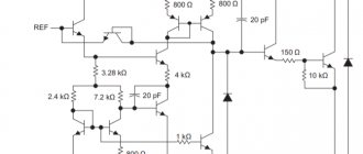
Rice. 5 Equivalent circuit of LM78LXX
Application
Rice.
6 Fixed Output Voltage Regulator * Required if the stabilizer is located closer than 3 inches from the power supply filter.
** See (1) in the electrical specifications table.
Rice. 7 Stabilizer with adjustable output voltage
VOUT = 5 V + (5 V/R1 + IQ) R2; 5 V/R1 > 3 IQ, load stabilization (Lr) ≈ [(R1 + R2)/R1] (Lr for LM78L05)
Rice. 8 Current stabilizer
IOUT = (VOUT/R1) + IQ
>IQ = 1.5 mA
Rice. 9 Stabilizer 5 V, 500 mA with short circuit protection
* Semiconductor tantalum capacitor
** Transistor Q1 is installed on the heatsink
***Connected additionally: reduces ripple and improves transient characteristics. Load stabilization: 0.6% 0 ≤ IL ≤ 250 mA with tON pulse = 50 ms.
Rice. 10 Stabilizer for 2-polar power supply at ±15 V, 100 mA
* Tantalum capacitor
Rice. 11 Stabilizer with adjustable output voltage 0.5 V - 18 V
* Tantalum capacitor
* VOUT = VG + 5 V, R1 = (−VIN/IQ LM78L05)
VOUT = 5V (R2/R4) for (R2 + R3) = (R4 + R5)
0.5 V output will correspond to the ratio (R2/R4) = 0.1 (R3/R4) = 0.9
If you find an error, please select a piece of text and press Ctrl+Enter.
How to test the 78L05 device using a multimeter
Before using the device, it must be checked with a multimeter. To do this, you need to ring the contacts to find out if there is a short circuit between them. If it is absent, the check continues.
The input voltage must be no less than 7 V, and no more than the maximum. For this, a regular crown with a voltage of 9 V is used. An additional load device, for example, a 1 Ohm resistor, is connected to the output.
When supplying power, observe polarity. The negative side is connected to the main terminal, and the “+” sign is connected to the input. The output voltage is disconnected from ground and is 5 V, according to the design of the chip.
How to check a linear stabilizer
How to test a zener diode with a multimeter
It was necessary to assemble input stabilizing power supply circuits for a device based on the PIC16F628 microcontroller that operates stably at a voltage of 5 volts. It is not difficult. I took the PJ7805 integrated circuit and made it based on it in accordance with the circuit from the datasheet. I applied voltage and got 4.9 volts at the output. Most likely, this is quite enough, but stubbornness, mixed with pedantry, took over.
I took out a box of integral stabilizers and set out to try on all the corresponding ones. And so as not to make a mistake, I even laid out the corresponding diagram in front of me. However, the enthusiasm ended already at the very first component. This “hedgehog without arms, without legs” made of connecting wires with crocodiles wanted to live his own life and obeyed the will of the radio amateur with great difficulty. Moreover, the tested stabilizer at the output showed 4.86 volts, which plunged my optimism into despondency.
No, something more significant is needed here, for example, some kind of albeit simple, but nevertheless a sample or something. I typed it into the Yandex search engine and got what you see in the photo “Complex for monitoring integrated voltage stabilizers.” Well, this is not for the average amateur radio mind. It became clear that the wheel would have to be reinvented.
Device analogues and manufacturers 78L05
In addition to the names already listed, there are several other types of device substitutes. Among them are foreign ones:
- TS78L05
- MC78L05
- TS78L05
- UA78L05
- MC78L05
Several high-quality accounts are also produced in Russia and Belarus, for example, KR1181EN5 and KR1157EN502.
Design of a laboratory source of electricity based on 78L05
The design in question is original, since it uses an atypical TDA2030 microcircuit, but the source of electricity here is the 78L05 stabilizer. Since the maximum operating input voltage of this device is 20 V, so that it does not break, the work continues not without the participation of a parametric stabilizer.
To connect the TDA2030 device we use a non-inverting device. As a result, a specific gain indicator is created. As a result, the voltage at the output of the electricity source is adjusted from 0 to 30 V when the resistor value changes. If it is necessary to change the highest output voltage, a resistor of the appropriate level is selected for this.
Connection schemes
The most typical circuit for connecting the 78L05 chip is a simple 3-pin stabilizer circuit. It is quite easy to do it yourself, and it does not require a large number of radio components. There are two containers connected to the input and output of the device. The input smooths out the oscillations received from the rectifying diode bridge. The output optimizes transients and reduces high-frequency output impedance. For the device to operate stably, the input voltage must be in the range from 5 to 20 V.
This stabilizer can be used to make a simple 5 V power supply. To increase the power and output current, the 78L05 must be installed on a radiator.
5V power supply without transformer
The main distinguishing feature of this scheme is its high stability. Its elements do not heat up, and all of them are accessible to ordinary users.
The unit includes an LED on/off indicator. There is no usual transformer here; a damping circuit with certain capacitance and resistance values is used. The unit is equipped with a rectifier bridge based on diodes and capacitors to reduce vibrations, and has a 9 V zener diode. And of course, the circuit will not be able to work without a special voltage stabilization device - 78L05.
It is necessary since the output voltage of the bridge is approximately 100 V. Because of this, the stabilizer may break. The stabilization level is in the range from 8 to 15 V.
The design does not have isolation from the electrical network of galvanic elements, so you need to use the power supply more carefully.
Design of the relay-regulator and external signs of its malfunction
Relay regulator:
- It can be made in the form of one of the modules of the brush assembly, using its structure as a supporting base.
- Or it is a separate element mounted on the body on a bracket.
The use of a separate design is easily visually detected due to the fact that the relay is located in the open circuit of the current flow between the generator and the battery. In any form of its design, the relay is a non-separable monoblock element, the body of which is filled with epoxy or other sealant. This means that a failed component cannot be repaired.
Failure of the relay regulator is accompanied by undercharging or overcharging of the battery. An undercharged battery results in
- the engine begins to start poorly;
- the starter is unable to crank the crankshaft;
- in severe cases, the car turns out to be de-energized and the remaining charge is not even enough to turn on the dashboard indicators.
An unpleasant consequence of overcharging a battery is boiling off of the electrolyte. At the same time, white deposits and streaks appear on its body in the area of the terminals and on the terminals themselves. External signs are not exhaustive and do not clearly indicate a relay malfunction. However, when they appear, a comprehensive check of the circuits and generator circuit is carried out, the list of procedures of which includes monitoring the serviceability of the relay regulator.
78L05 Standard Power Supply
The spread of variable volts in the specified design takes limits of 5-20 V. The output voltage changes thanks to a resistor with variable values.
The maximum load current is 1.5 A. Here the device 78L05 is replaced with 7805 or its Russian version - KR142EN5A. Instead of VT1, another transistor, KT315, is also used. Possessing high power, VT2 is placed next to the radiator, which measures 150 cm2.
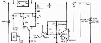
How charging works for different types of electronics
Let's look at a simple and widely used design. All possible lithium, nickel, and lead batteries used in uninterruptible devices are charged from the resulting device.
When the battery is being charged, the charger's amperage is of particular importance. Normally, it is approximately 1/10 of the battery capacity. The constancy of this value, in turn, is ensured by the 78L05 stabilizer.
There are 4 options for charging current spread, from 50 to 200 A. They depend on the resistance value.
With a stabilizer output voltage of 5 V, to obtain a current of 100 mA, you need to use a resistor with a resistance of 100 Ohms. And so - with each of the values.
In addition, the circuit has an indicator, which is based on 2 transistors and a light diode. The latter is extinguished when the charge runs out.
Diode testing without soldering
How to check battery capacity with a multimeter
When testing elements inside circuits, some difficulties arise in determining their characteristics, since the measuring device tests all parts of the circuit connected between its measuring probes. Thus, it is necessary to exclude possible options for the flow of current in the circuit in which the desired element is installed. The easiest option is to unsolder one of the terminals of the diode you need to test. Then the measurement results will be reliable. After desoldering one of the terminals of the element, you can check it using any of the methods listed above.
If desoldering one of the pins is problematic, turn off the power supply to the circuit and try to test the diode without desoldering it. In this case, the circuit should not contain elements that bridge the element being tested. The test results must also be reliable.
Non-DC power supply
The “negative” connection in the opposite direction goes through the load resistance. A certain number of volts are concentrated at the inversion input of the microcircuit (TDA2030). Under its influence, a current passes through the additional element. It does not depend on the load rating of the resistor.
It turns out that if you adjust the voltage that came from a device with variable resistance, with its constant value, the load current can be changed within 0.5 A. Using such a circuit, it is easy to charge any type of battery. Throughout the entire charging period, the current remains at the same level. It does not depend on whether the battery is discharged or how stable the electrical network is. The maximum charging current can be adjusted with a resistor by changing its resistance.
You can buy 78L05 and other devices of the 78Lxx type in China on the Aliexpress website using the link.
Technical parameters and pinout of stabilizer 78L05:
- Input voltage: 7 to 20 volts.
- Output voltage: 4.5 to 5.5 volts.
- Output current (maximum): 100 mA.
- Current consumption (stabilizer): 5.5 mA.
- Permissible input-output voltage difference: 1.7 volts.
- Operating temperature: -40 to +125 °C.
More circuits on adjustable voltage regulators
As shown in the block diagram above, there are built-in voltage references. There are many voltage amplification stages for the op amp used here. Thus, the current flowing through the potential divider can be written as. Thus, the output voltage can be written as: This increase in temperature may be mainly due to excessive external stress, ambient temperature, or even heat loss.
Pins 1, 2 and 3 are input, output and ground. Otherwise, it will stop regulating. In addition, there is a maximum input voltage due to excessive power dissipation. In switching regulators, the output voltage is regulated by controlling the switching time of the feedback circuit; that is, by adjusting the duty cycle. The regulators discussed above are linear voltage regulators that require a series transistor to regulate in the active region.