The l7805cv linear voltage regulator helps achieve a constant 5 V voltage at a current of no more than 1.5 A. This IC has 3 pins, so it is used in many electronic applications. It has internal overheat protection, a circuit that limits current buildup. The device has positive polarity.
Keep in mind that the l7805cv is not a transistor. Often, beginner radio electronics engineers mistakenly believe this because the device has only 3 outputs. At the same time, in the internal structure of the device in question there are 17 semiconductor triodes.
Pinout l7805cv
Take a look at the l7805cv datasheet before purchasing the unit. You need to take a closer look at the full designation of this stabilizer. If the part has a thick metal backing, it ends with two letters dg.
Let me explain where this came from. 15 years ago, a number of companies, including STM, changed the design of the TO-220 housing. As a result, their different variants arose - single and double caliber. The manufacturer stated that there are minor differences in the performance of different versions of its products. But different thermal resistance indicators are not indicated in the technical description. They can be seen in this image.
The l7805cv pinout is typical for such devices in an updated version of the case. Three “legs”: input, output and ground are physically connected to the ground pin. The metal substrate is thinner, it has a thickness of 0.5-0.6 mm.
The l7805cv chips with the letter “DG” at the end of the package name are equipped with a larger substrate. They have a thickness of approximately 1.2-1.3 mm.
l7805cv - main characteristics
According to the datasheet, this device is included in the 178 series and the l7805c batch. It, in turn, contains various plastic packaging:
- TO-220.
- D²PAK.
- DPAK.
- TO-220FP.
Externally they differ, but the maximums of key quantities in all products included in this line are indistinguishable.
Highs
Let's talk about the largest values of the quantities for the device in question:
- Input voltage: 35 V at zero value from 5 to 15 V, 40 V - from 20 to 24 V.
- Temperature allowed for operation is from 0 to 125 degrees.
- Temperature allowed for storage is from -65 to 150 degrees.
The power dissipation and output current of such devices are limited by the housing design and internal protection. The operating instructions mention that normal operation of the microcircuit in this mode is not always possible. If one of the listed values is exceeded, the device may break down.
Please note that the smallest difference between the input and output voltages for the device to work should be somewhere between 2-3 V. The maximum output current is provided only when the difference between the initial and final voltages is from 5 to 15 V.
So don't supply more than 15V power to the chip. To increase the output current, according to the manufacturer, it is necessary to place the device on a radiator. This should be done even when the output current is 300 mA, due to the high temperature of the device during operation. When the temperature of the crystal increases, the stabilized voltage drops.
Electrical parameters
Below are the device parameters from the instructions, for a typical stabilization circuit, using classic voltage smoothers at the input and output, 0.33 and 0.1 μF, respectively. In this case, the supply voltage is 10 V, and the current is 0.5A. The instructions also indicate that voltage surges during experiments, according to temperature changes, are not taken into account. The highest crystal temperature is 25 degrees.
The presented characteristics are taken from the English version of the datasheet.
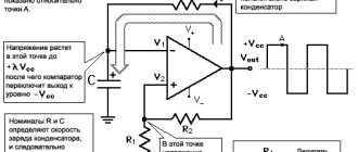
Current source circuit for 78xx
The current value is set by resistor R*, which is the load for the stabilizer. In this case, the stabilizer is not grounded. Grounding occurs only through the load Rн. This switching circuit forces the microcircuit to try to provide a given current to the load by adjusting the output voltage.
l7805cv: analogues
The stabilizer has a number of modern substitutes. These are not as popular lines as STM's L78, but are produced by fairly well-known manufacturers:
- Texas Instruments (LM340AT-5.0, UA7805CKCS),
- ON Semiconductor (MC7805CTG),
- Fairchild (LM7805CT).
The L7805ABP has the same characteristics, but its body is made entirely of plastic. There is no metal backing in this device.
There is another possible replacement, the L7805CT. It is contained in durable metal-treated packaging.
Manufacturers
The original L78 devices are manufactured by the European company STMicroelectronics (STM), which is constantly improving the quality of its products.
The latest versions of the device from the named company are certified by ECOPACK. They comply with international eco-standards. Since the device has enough analogues, and it is sold at an adequate price, up to approximately 50 rubles, counterfeits are almost impossible.
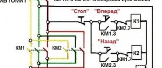
l7805cv: connection diagram
Anyone, even not the most experienced electronics engineer, can design an electricity source with a stable output voltage according to the 7805 circuit, and its analogues. Let's consider a linear corrector for a stable input voltage.
The figure shows a typical connection of a linear zener diode with a positive polarization of 5V and a minimum current for operation of 1.5 A. The parameters of the microcircuit have become so widely known that many production leaders have taken up their manufacture. And the next figure shows a more advanced diagram. It works when the capacitances of capacitors C1 and C2 increase.
Usually, in the amateur radio environment they use a simplified name for this chip and do not name the letter designations that appear in front and indicate the manufacturer. Most people already understand that this is a stabilizer, and the last number in its name indicates the output voltage.
Beginners who have not yet seen these electronic components in reality and have a minimum of information about them should know that the main condition for proper assembly is high-quality components.
It's no secret that when purchasing parts it is very important to consider where they were produced. Both the brand and the supplier matter. For example, quality products are made by STMicroelectronics, a microelectronics manufacturer.
Stabilizers without a name from unknown manufacturers usually have a minimal price compared to popular brands. But they cannot always be called high quality. Their operation is most affected by the difference in output voltage.
I often came across microcircuits that output 4.5 V, and not 5 V, as expected. Other options from the same line, on the contrary, had an exceeded value, for example, 5.5 V. Also, these samples often have their own strong background, they have increased energy consumption.
Diagram of the energy source, which is made on L78xx elements
The output current is determined by a stable resistor, which is connected in parallel to a 0.1uF capacitor. This resistance creates a load for the device. The stabilizer does not have a ground connection. Only 1 output, the load resistance, is directed to ground. The operation of such a connection circuit requires the delivery of a specific current to the load by regulating the output voltage.
One of the shortcomings of the circuit is the summation of the output quiescent current Id. The parameters of this indicator are indicated in the documents for the microcircuit. As a rule, such devices have a constant quiescent current of 8 mA. This is the smallest current in the output circuit. This means that it is impossible to design a power source with a lower value.
The maximum that can be achieved from such an attempt is to obtain output currents from 8 mA to 1A. But, if the current values exceed from 750 to 850 mA, it is necessary to install the structure on a radiator. Working at such current levels is not profitable.
The current 1A, which is stated in the documents, is the maximum. In fact, the chip may overheat and break. Therefore, the most reasonable output current is in the range of 20 to 751 mA.
Permissible output current and voltage level
The change in current at rest is 0.5 mA. With this value, we can assume that the output current settings are correct. This means that the accuracy of its installation is affected by the load resistance of the structure.
In such a situation, you need to use precision resistors that have high stability and significant accuracy within ±0.5%.
Permissible load resistance
It is impossible not to take this value into account. Everything is very clear here: everything can be calculated using Ohm’s law. For example, let’s substitute the values into the formula: V= I*R = 0.15 * 100 = 15 V.
Using these simple calculations, we find out what the load voltage should be with a resistance of 100 Ohms in order to obtain the output current. According to this formula, it turns out that the best option is to use 7812 or 7815 microcircuits, designed for 12-15 V, in reserve.
Of course, this source scheme has its limitations. It can be used in many solutions where great accuracy is not so important. The simplicity of the circuit allows you to create a current source under almost any circumstances, especially considering that purchasing parts for it is extremely simple.
Component quality
In reality, the manufacturer is very important. Always try to buy stabilizers, and any parts from major manufacturers and trusted suppliers. I personally prefer STMicroelectronics. They are distinguished by the ST emblem in the corner.
Noname stabilizers or those produced by Chanhanbzdyun's grandfather very often have a significant variation in output voltage values from product to product. In practice, it was found that the 7805 stabilizer, which should give 5 volts, gave 4.63, or some samples gave up to 5.2 volts.
It would be fine, it keeps the voltage constant, but the problem is that the emissions and background are several times stronger and the consumption of the stabilizer itself is greater. I think you understand.
l7805cv: how to check with a multimeter
A failed stabilizer affects the voltage of the current source, and therefore the functioning of the device. Therefore, a radio electronics engineer must know how to check its serviceability using a multimeter.
Turn the multimeter into resistance measurement mode. If you connect it to the stabilizer directly, the minimum resistance value will be displayed on the device screen. When connecting back, infinity will be displayed. This means that the semiconductor is working properly.
Checking the stabilizer using a multimeter in diode testing mode is similar. Then the forward direction will correspond to a decrease in voltage in the range from 400 to 600 mV, the reverse direction will correspond to infinity.
Take a look at the picture to see how this happens.
A broken diode will show a slight deviation of resistance from zero. If the pn junction is broken and in any direction of switching on, the device will not have any readings.
The stabilizer is checked in the same way, which is not desoldered from the circuit. Then the device always shows the resistance of the components connected in parallel. Sometimes, under such circumstances, verification is impossible.
But it cannot be said that testing with a primitive tester is sufficient, because in addition to breakdown and breakage of the transition, there are other conditions. A complete check is possible if you create a compact diagram.
How to make sure that the microcircuit is operational? First, just test the leads using a multimeter. If a short circuit occurs even once, the element is faulty. If you have a power source with a voltage of 7 V or more, assemble the circuit using the datasheet and apply power to the input. At the output, use a multimeter to record a voltage of 5 V, this will mean the element is fully operational.
Current accuracy and output voltage
In this case, the instability of the quiescent current is ΔId = 0.5 mA. This value determines the accuracy of setting the output current. Also, the accuracy of setting the output current value is determined by the accuracy of resistance R*. It is better to use a resistor with an accuracy of no worse than 1%.
A certain convenience here is the fact that the circuit cannot produce a voltage higher than the specified stabilization voltage. For example, when using a 7805 stabilizer, the output voltage cannot exceed 5 volts. This can be critical.