Modern radio-electronic devices use a very wide range of various electronic devices. Sometimes the absence of one or more of these elements can slow down or even interrupt the installation or layout of a circuit.
Very often there are situations when it is necessary to replace one element with another . If we are talking about simply replacing one value of a resistor or capacitor with another, then the solution to the problem of replacement or selection of a replacement value is obvious. Less obvious are the replacements of radioelements that have specific properties inherent only to them.
Below we will consider the issues of replacing some special semiconductor devices with their equivalents made from more affordable elements.
In pulse technology, controlled and uncontrolled switching elements with a current-voltage characteristic with an N- or S-shaped section are widely used. These are avalanche transistors, gas dischargers, dinistors, thyristors, triacs, unijunction transistors, lambda diodes, tunnel diodes, injection field-effect transistors and other elements.
Bipolar avalanche transistors are widely used in relaxation pulse generators and various converters of electrical and non-electric quantities into frequency. It should be noted that such transistors are almost never produced specifically. In practice, ordinary transistors are used for these purposes in an unusual switching on or operating mode.
Equivalent to an avalanche transistor and dinistor
An avalanche transistor is a semiconductor device operating in avalanche breakdown mode. Such a breakdown usually occurs at a voltage exceeding the maximum permissible value.
Thermal breakdown (irreversible damage) of the transistor can be prevented by limiting the current through the transistor (by connecting a high-resistance load).
Avalanche breakdown of a transistor can occur in “direct” and “inverse” switching of the transistor. The avalanche breakdown voltage during inverse connection (the polarity of connecting the semiconductor device is opposite to the generally accepted, recommended one) is usually lower than for “direct” connection.
The base pin of the transistor is often not used (not connected to other circuit elements). In some cases, the base pin is connected to the emitter through a high-resistance resistor (hundreds of kOhms - units of MOhm). This allows you to regulate the avalanche breakdown voltage within certain limits.
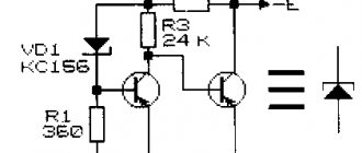
In Fig. Figure 1 shows a diagram of an equivalent replacement of the “avalanche” transistor of the K101KT1 integrated chopper with its discrete analogues. It is interesting to note that upon closer examination, this circuit is identical to the equivalent circuit of a dinistor (Fig. 1), a thyristor (Fig. 2) and a unijunction transistor (Fig. 4).
Let us note in passing that the type of current-voltage characteristics of all these semiconductor devices has common characteristic features. Their current-voltage characteristics have an S-shaped section, a section with the so-called “negative” dynamic resistance. Thanks to this feature of the current-voltage characteristic, the listed devices can be used to generate electrical oscillations.
Rice. 1. Analogue of an avalanche transistor and dinistor.
Checking the dinistor using an oscilloscope
If you have an oscilloscope, then we can assemble a relaxation generator using the tested DB3 dinistor.
In this circuit, the capacitor is charged through a 100k resistor. When the charge voltage reaches the breakdown voltage of the dinistor, the capacitor is sharply discharged through it until the voltage decreases below the holding current at which the dinistor closes. At this moment (at a voltage of about 15 volts), the capacitor will begin to charge again, and the process will repeat.
The period (frequency) from the beginning of the capacitor charge until the breakdown of the dinistor depends on the capacitance of the capacitor itself and the resistance of the resistor. With a constant resistor resistance of 100 kOhm and a supply voltage of 70 volts, the capacitance will be as follows:
- C = 0.015 µF - 0.275 ms.
- C = 0.1 µF - 3 ms.
- C = 0.22 µF - 6 ms.
- C = 0.33 µF - 8.4 ms.
- C = 0.56 µF - 15 ms.
(242.6 KiB, downloads: 10,927)
Thyristor equivalent
Thyristors, dinistors and similar elements are capable of controlling large powers supplied to the load with very minor internal losses.
Thyristors are devices that have two stable states: a low conductivity state (no conductivity, the device is locked) and a high conductivity state (conductivity is close to zero, the device is open). Representatives of the thyristor class [A.I. Vishnevsky]:
- diode thyristors ( dinistors , diacs), having two terminals (anode and cathode), controlled by applying voltage to the electrodes with a high rate of increase or increasing the applied voltage to a value close to critical;
- triode thyristors ( thyristors , triacs), three-electrode elements, the control electrode of which serves to transfer the thyristor from a closed state to an open state;
- tetrode thyristors having two control electrodes;
- symmetrical thyristors - triacs having a five-layer structure. Sometimes this semiconductor device is called a semistor.
Diode thyristors (dinistors) , the range of which is not so large, differ mainly in the maximum permissible direct forward voltage in the closed state.
Thus, for dinistors of types KN102A, B, V, G, D, E, ZH, I (2N102A - I), the values of these voltages are, respectively, 5, 7, 10, 14, 20, 30, 40, 50 V with reverse current no more than 0.5 mA. The maximum permissible DC on-state current for these semiconductor devices is 0.2 A with a residual on-state voltage of 1.5 V.
In Fig. Figure 1 shows the equivalent circuit of a low-voltage dinistor. If we take R1 = R3 = 100 Ohm, we can obtain a dinistor with a controlled (using resistor R2) switching voltage from 1 to 25 V [Ya. Voitsekhovsky, R 11/73-40, R 12/76-29]. In the absence of this resistor and under the condition R1 = R3 = 5.1 kOhm, the switching voltage will be 9 B, and with R1 = R3 = 3 kOhm - 12 V.
An analogue of a thyristor with a p-p-p-p structure, described in the book by J. Wojciechowski, is shown in Fig. 2. The letter A indicates the anode; K - cathode; UE - control electrode. In the circuits (Fig. 1, 2) transistors of the KT315 and KT361 types can be used.
It is only necessary that the voltage supplied to the semiconductor device or its analogue does not exceed the maximum rated values. The table (Fig. 2) shows what values of R1 and R2 should be used as a guide when creating an analogue of a thyristor based on germanium or silicon transistors.
Rice. 2. Analogue of a thyristor.
In the breaks in the electrical circuit, shown in the diagram (Fig. 2) with crosses, you can include diodes that allow you to influence the type of current-voltage characteristic of the analogue. Unlike a conventional thyristor, its analogue (Fig. 2) can be controlled using an additional output - the control electrode EDOP, connected to the base of the transistor VT2 (top picture) or VT1 (bottom picture).
Typically, the thyristor is turned on by briefly applying voltage to the control electrode of the UE. When voltage is applied to the electrode, the thyristor, on the contrary, can be switched from the on state to the off state.
How to check DB3 dinistor
The only thing that can be determined with a simple multimeter is a short circuit in the dinistor, in which case it will pass current in both directions. This type of dinistor check is similar to checking a diode with a multimeter.
To fully check the performance of the DB3 dinistor, we must smoothly apply voltage, and then see at what value the breakdown occurs and the conductivity of the semiconductor appears.
Power supply
The first thing we need is an adjustable DC power supply from 0 to 50 volts. The figure above shows a simple diagram of such a source. The voltage regulator indicated in the diagram is a regular dimmer used to adjust room lighting. Such a dimmer, as a rule, has a knob or slider to smoothly change the voltage. Network transformer 220V/24V. Diodes VD1, VD2 and capacitors C1, C2 form a half-wave voltage doubler and filter.
Verification steps
Step 1 : Set zero voltage on pins X1 and X3. Connect a DC voltmeter to X2 and X3. Slowly increase the tension. When the voltage on a working dinistor reaches about 30 (according to the datasheet from 28V to 36V), the voltage on R1 will sharply rise to about 10-15 volts. This is due to the fact that the dinistor exhibits negative resistance at the moment of breakdown.
Step 2 : Slowly turn the dimmer knob toward decreasing the power supply voltage, and at about 15 to 25 volts, the voltage across resistor R1 should drop sharply to zero.
Step 3 : It is necessary to repeat steps 1 and 2, but by connecting the dinistor in reverse.
Injection field effect transistor equivalent
An injection field-effect transistor is a semiconductor device with an S-shaped current-voltage characteristic. Such devices are widely used in pulse technology - in relaxation pulse generators, voltage-frequency converters, waiting and controlled generators, etc.
Such a transistor can be made by combining field-effect and conventional bipolar transistors (Fig. 5, 6). Not only the semiconductor structure can be modeled based on discrete elements.
Rice. 5. Analog of an injection field-effect transistor with a n-structure.
Rice. 6. Analog of an injection field-effect transistor with a p-structure.
Equivalent to low voltage gas arrester
In Fig. Figure 7 shows a diagram of a device equivalent to a low-voltage gas discharger [PTE 4/83-127]. This device is a gas-filled cylinder with two electrodes, in which an electrical interelectrode breakdown occurs when a certain critical voltage value is exceeded.
The “breakdown” voltage for an analogue of a gas spark gap (Fig. 7) is 20 V. In the same way, an analogue of, for example, a neon lamp can be created.
Rice. 7. Analogue of a gas discharger - equivalent replacement circuit.
Completion
In conclusion, it would be useful to remind you of a few things. First, be careful when testing the regulator. There is high voltage there, which can, if not kill a person, then lead to burns and pain. Secondly, be careful when selecting a triac from analogues. Consider load power, current and voltage. Thirdly, when manufacturing regulators according to this scheme for a more powerful load, it is worth abandoning the hinged installation. The parts must be soldered on the board and placed in a separate case.
Equivalent replacement of lambda diodes
Semiconductor devices such as lambda diodes and tunnel diodes . The current-voltage characteristics of these devices have an N-shaped section.
Lambda diodes and tunnel diodes can be used to generate and amplify electrical signals. In Fig. 8 and fig. Figure 9 shows circuits simulating lambda di-od [RTE 9/87-35].
In practice, generators often use the circuit shown in Fig. 9 [PTE 5/77-96]. If a controlled resistor (potentiometer) or transistor (field-effect or bipolar) is connected between the drains of the field-effect transistors, then the type of current-voltage characteristic of such a “lambda diode” can be controlled within wide limits: adjust the generation frequency, modulate high-frequency oscillations, etc.
Rice. 8. Analog of a lambda diode.
Rice. 9. Analog of a lambda diode.
The use of triac regulators in everyday life
Such devices are used in everyday life wherever there is a need to smoothly change the power of a device or tool. In general, this scheme works on the principle of reducing the mains voltage of 230 V. And if the supply voltage of an electrical appliance is reduced, then its power will change proportionally.
Example. Let's say we have a soldering iron with a power of 80 W designed for a mains voltage of 230 V. This power is too much for soldering conventional radio components and thin wires. The tip overheats, the rosin burns and turns black, the solder does not stick, but rolls up into balls. This means that the temperature at the tip of the tip is too high.
But if you reduce the power of such a soldering iron, then the listed problems will disappear. This can be done by reducing its supply voltage from 230 V to, for example, 80 V (almost three times). And since the power (as well as the heating temperature of the tip) decreases proportionally, we will end up with a 25-30 W soldering iron. Triac regulators are used to smoothly change power:
- soldering irons (it was for the soldering iron that the device described in the article was made);
- electric fruit dryers;
- irons;
- heaters;
- other heating devices;
- vacuum cleaners;
- power tools – grinders, orbital sanders, jigsaws;
- other equipment with engines - grinding machines, drilling machines and others;
- incandescent lamps.
Read also: How to solder transistors correctly
Regarding the last point, it is worth noting that this particular triac regulator circuit is not very suitable. But this is also discussed in more detail below.