Characteristics
All its parameters can be divided into two types: limiting and electrical. Let's look at them in more detail. Please note that the device cannot operate at the limit values indicated below for a long time; these are peak values that it will withstand in a very short period.
The electrical parameters of ku202n characterize the operation of the thyristor under operating conditions. Below are their meanings:
Equivalent replacement for tunnel diodes
Rice. 10. Analogue of a tunnel diode.
Tunnel diodes are also used to generate and amplify high-frequency signals. Some representatives of this class of semiconductor devices are capable of operating at frequencies that are hardly achievable under normal conditions - on the order of several GHz. A device that allows you to simulate the current-voltage characteristic of a tunnel diode is shown in Fig. 10 [R 4/77-30].
Analogs
Foreign analogues of the KU202N thyristor are VTX32S100, H20T15CN, 1N4202. Foreign manufacturers do not produce devices with the same geometric dimensions as the KU202N, so you will need to change the location for mounting the device. It should also be taken into account that their parameters may differ slightly from the thyristor in question, for example, the average current may be 7.5 A.
In addition to foreign devices, you can use the Russian analogue - T112-10. Like KU202N, it has a metal body and an anode outlet for thread. However, its dimensions are smaller, so the installation location will still have to be changed.
Connection diagram
There is a standard connection diagram for the Ku202N that must be followed. According to it, a shunt resistor with a resistance of 51 Ohms is connected between the cathode and the control electrode. The deviation from the nominal value should not exceed 5%.
To prevent the thyristor from breaking down, it is not allowed to supply control current if the voltage at the anode is negative. This may result in device failure beyond repair.
Installation features
A force greater than 0.98 N cannot be applied to the cathode and control electrode. When attaching the device to the heat sink, the tightening force should not be higher than 2.45 Nm.
You cannot solder the cathode at a distance closer than 7 mm. from the glass body. For the control electrode, the permissible soldering distance is 3.5 mm. The temperature of the soldering iron should not be higher than +260 0 C. Soldering time should not be more than 3 s.
Checking for serviceability
You can check the Ku202n thyristor for serviceability with a multimeter; you should start by checking the np junction between the anode and the control electrode. It should ring in the same way as a regular diode, that is, when connected directly (positive voltage to the control electrode, and negative to the cathode), the transition resistance should be small, and when connected in reverse, large.
For a more detailed check, you need to perform the following steps:
- Switch the multimeter to the position for measuring resistance up to 2 kOhm. The probes of the device must be supplied with voltage from the power source.
- Now you need to connect the multimeter probes to the anode and cathode of the thyristor. In this case, the device should show a high resistance, close to infinity.
- Using a jumper, we connect the anode and the control electrode. The resistance between the anode and cathode, as shown by the multimeter, should drop.
- We disconnect the anode and the control electrode. Resistance must grow.
You can also test the thyristor using a light bulb and a DC power supply. The light bulb must be designed for the voltage supplied by the power supply. We connect the positive pole of the power supply to the anode, and the negative pole to the cathode of the thyristor being tested.
Using a battery or the probes of a multimeter turned on in ohmmeter mode, we apply an unlocking voltage to the control electrode. To do this, connect a positive voltage to the anode, and a negative voltage to the control electrode. If the thyristor is working properly, the light should light up.
If you remove the voltage between the anode and the control electrode, the light bulb should continue to light.
There is a way to test the Ku202n thyristor without removing it from the circuit. To do this you need:
- Disconnect the board on which the thyristor is located from the power supply.
- We disconnect the control electrode from the circuit.
- We connect one tester configured to measure DC voltage to the anode and cathode of the thyristor.
- We connect the second multimeter between the anode and the control electrode.
- The first tester should show a small voltage (tens of millivolts).
Although it has been discontinued, you can still buy it in some places. In addition, it is present in many old electronic devices, from which it can be removed if desired. Its DataSheet can be downloaded here.
Thyristor KU202N belongs to the group of triode devices with a p - n - p - n structure. The junctions are created by planar diffusion of silicon. The thyristor is designed to switch high voltages using small levels through an additional output. Depending on the switching circuit, it can open or close, providing the required operating modes of the device. It is used in blocking systems, protection systems, servo drives, remotely controlled switching systems, chargers as a switch or charge current regulator.
Dinistor continuity test
If necessary, you can check the dinistor. Key points include the following:
- To carry out the test, a high voltage power source is required, the rating of which is higher than that of the dinistor.
- You can limit the current by connecting a resistor with a resistance value from 100 to 1000 Ohms.
- The positive wire is connected to the anode, and the cathode to the terminal of the limiting resistor. The free end of the resistance is connected to the minus of the power supply.
The measuring device used in the appropriate mode is connected to the anode and cathode through special probes. The tester should be within the millivolt limit, after which the dinistor opens.
Design
Structurally, the KU202N thyristor and the entire series are made in a metal case made of coated copper alloy, which has threaded terminals and two solder terminals of varying thickness and height. The size of the threaded outlet or anode (A) is M6 for the nut. The terminals are made rigid by filling with epoxy resin, but during installation, forces should not be used more than 0.98 N.
When soldering the power terminal (K), it is necessary to maintain a minimum distance to the glass of at least 7 mm, since high temperatures may damage its integrity. When connecting the control output (CE), you should maintain a distance to the glass of at least 3.5 mm for the same reason. In this case, the total holding time of the soldering iron is not recommended to exceed more than 3 s. The effective temperature of the soldering tool tip should not exceed +260 degrees.
Features of circuit connection
The thyristor is designed for voltage switching in various devices . But at the same time, there is a standard scheme for connecting it, which is highly recommended not to be violated. For example, a resistor must be connected between the cathode (solder pin) and the control electrode as a shunt component. Thanks to its presence, the control circuit is closed and the transition is saturated. Its resistance should be no more and no less than 51 Ohms.
If there is a voltage of negative polarity at the anode, then the control current should be zero. Otherwise, an electrical breakdown of the junction will occur, which will lead to a malfunction of the entire device. Its further operation is impossible, as is reverse restoration.
Equivalent to low voltage gas arrester
In Fig. Figure 7 shows a diagram of a device equivalent to a low-voltage gas discharger [PTE 4/83-127]. This device is a gas-filled cylinder with two electrodes, in which an electrical interelectrode breakdown occurs when a certain critical voltage value is exceeded.
The “breakdown” voltage for an analogue of a gas spark gap (Fig. 7) is 20 V. In the same way, an analogue of, for example, a neon lamp can be created.
Rice. 7. Analogue of a gas discharger - equivalent replacement circuit.
Thyristor technical parameters
Thyristor KU202N belongs to the group of high-voltage devices designed to operate at voltages up to 400 V with a maximum permissible direct current in the open state of no more than 10 A. In total, the line includes 12 models of thyristors with different voltages in the closed state. Therefore, when choosing, this is the main parameter.
Thyristors with letter designations from K to N are intended for use in circuits with voltages of 300 volts and above. As for the other parameters, they remain the same. Quite often, newbie radio amateurs encounter such problems, which leads to additional waste.
These thyristors are quite often used in the construction of power regulators with a load of no more than 2 kW. But it is highly not recommended to operate it in critical modes . A current of no more than 7-8 A should be passed through the device, which will provide the most effective and gentle modes.
Thyristor in an electrical circuit: what kind of semiconductor is it
If we use scientific terms, we can see that the design of this complex electronic device includes a semiconductor single crystal with three or more pn junctions.
They are made in order to change its conductivity to two critical states, when it:
- It is open and allows electric current to pass through it.
- Completely closed.
To connect to an electrical circuit, it is usually equipped with three, two or four leads from the contact pads of the pn layers.
I will not continue this topic in scientific language, because beginners will not understand anything, and it is difficult for me to explain in simple terms how charge carriers (holes and electrons) move throughout this structure in each specific case.
And no one needs this now except students trying to pass an exam, and workers designing and developing new devices.
A home electrician simply needs to understand the operating principle of the final device in order to be able to check its serviceability and competently operate it in everyday life.
Therefore, I show the final result - what the volt-ampere characteristic of the thyristor looks like during its operation.
It highlights two areas of the operating state with direct and reverse application of voltage, forming five modes depicted in the picture. Let’s not go deep into the theory and draw some brief conclusions for ourselves:
- at the initial stage of the forward bias region, the semiconductor is closed, then it opens and remains open;
- when connected back to the voltage source, it initially does not pass current, but when it reaches a critical state, it breaks through.
What does a thyristor look like and is indicated on electrical diagrams?
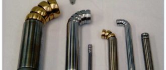
Modern industry uses a huge range of these unique semiconductors. They are available in different housings with the capabilities of transmitting and switching various powers.
I present the appearance of only a small part of them, manufactured in a metal case designed to work in power circuits with high currents.
There are also designs produced in a plastic case, which allows switching currents of lower values. They are used in control circuits of various household devices.
Externally, a thyristor looks like a diode.
Only in most cases it has an additional terminal for connecting to an external circuit - a control electrode. The designation on the diagram is also approximately the same.
The change concerns only a small addition to the cathode terminal - a small broken line. All this is clearly visible when compared.
It is no coincidence that the appearance of diodes and thyristors, as well as their designations on the diagrams, are similar. Although they are slightly different in design, they work according to the general principle: they pass electric current only in one direction.
I present this question more specifically below.
How to easily understand the operating principles and scientific terms of this complex semiconductor: 2 mneumonic rules
Commandment No. 1 for a beginner
Let's imagine that we are rafting on a large raft along a wide river. We can only move with the flow, and not against it. The flow of water moves due to the difference in heights (potentials), which have different levels of potential energy.
So the current in the diode can only flow in one direction: from the anode to the cathode. A different movement of electrons blocks the semiconductor transition. There are no other means of regulation here.
All this fully corresponds to the operation of a thyristor, but with small additions: the diode immediately opens when voltage is directly applied to its terminals.
In this case, the thyristor is closed and does not conduct current. It acts like a dam with locks blocking the river. Our raft will simply stop in front of the obstacle that has arisen. To resume movement, he needs to open the water barrier gate.
All this is done by command, when a current pulse of a certain direction is supplied through the control electrode, for example, to the anode (with appropriate control).
Only in this case, the closed semiconductor junction opens and maintains its state as long as a direct input voltage is applied to it.
If the current pulse disappears, this does not affect the operation of the semiconductor junction: it remains open. To close the thyristor, it is necessary to: break the power circuit anywhere or remove the voltage source from operation, or reliably bridge the anode with the cathode.
This simple mneumonic rule, based on a comparison of hydraulic and electrical processes, makes it easier to work with this complex electronic product.
Testament No. 2: features of the use of thyristors inside DC and AC circuits
The internal resistance of semiconductor junctions in the open state is quite small. The current through it is determined by Ohm's law, and with an applied constant voltage it does not change in magnitude.
In this case, the thyristor control circuit does not allow its strength to be adjusted. It needs to be regulated by other means.
The current pulse supplied by the control command is regulated to a safe value by the connected current-limiting resistor R.
This is done to prevent breakdown of the layer of semiconductors involved in the flow of the control signal.
How does a thyristor work in the circuit of household appliances running on alternating current?
Other prospects are created by variable circuits, and especially sinusoidal voltage sources. Their signal does not have a strictly constant value, but a sinusoid shape that changes over time.
Here, each oscillation period consists of two half-periods:
- positive;
- negative.
They have their own signs on the graph: “plus” and “minus”. In reality, when the half-cycle changes, the direction of current flow changes to exactly the opposite.
When the sine wave reaches zero amplitude, the current through the semiconductor junction stops and it closes. To resume the process, it is necessary to again apply a pulse to the control electrode at the next positive half-cycle.
All this happens automatically. At the same time, shifting the position of the opening pulse in time (in the angular measurement system - in phase) allows you to regulate the current strength by changing the moment of opening of the transition.
Connecting a second thyristor with the appropriate polarity to the lower half-wave allows you to adjust its value. Then we do not get a pure sinusoidal shape, but a slightly trimmed one in time (until the moment the control pulse is turned on).
3 variants of such a signal are shown in the lower graph of the output current when two thyristors are opened at the moments:
- increasing half-wave;
- on its amplitude;
- and in recession.
Our power tools are powered by such cut-off, and not purely sinusoidal, current: drills, rotary hammers, grinders and other devices with thyristor or triac control.
In general, there is nothing wrong with such a change in the signal shape: all manufacturers conducted a lot of experiments and put this circuit into operation.
We need to clearly understand all this, because when repairing or adjusting using an oscilloscope, such voltage signals must be traced at the control points of the electrical circuit.
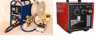
Rectifier devices with current regulation - the second principle of operation
Circuits of chargers, start-charging devices and DC welding machines operate on rectified voltage. In this case, the rectification devices of a typical diode bridge are often replaced by a transformer conversion of a single-phase signal with two diodes or thyristors.
It is commonly called full-wave rectification.
Here, a thyristor is mounted in each output half-winding of the power transformer, processing its own half-wave.
Rectification is achieved by connecting half-windings with a common point and choosing the direction of connecting the anode-cathode circuit of each semiconductor device.
The final shape of the rectified and modified signal is as follows.
Again, for comparison with the previous principle, I show the waveforms in three options for triggering a phase-shifting control pulse. Here you can see that the negative half-cycle has turned over, but the operation of the control circuit has not changed.
Rule No. 3: differences between transistor and thyristor control
It somehow happened to me that first I had to practically master electronic circuits operating on transistors, and only after them - thyristor assemblies.
Therefore, I first understood and remembered that the output signal on the transistor can be changed due to the magnitude of the potential difference at its base, that is, voltage.
My friends explained that a thyristor circuit, as a rule, is opened by a current flowing through the control electrode.
This small addition to the above material is worth remembering for beginners. And in order to understand the difference between the strength of the electric current and the magnitude of the effective voltage, I wrote two separate articles.
I recommend that you familiarize yourself with them in more detail. They are also presented in simple language.
Thyristor check
Many people are interested in how to check the KU202N thyristor and how to properly turn it on in the device to check its functionality. The fact is that quite often it turns out to be faulty for various reasons. Moreover, defects also occur in new products.
You can check the thyristor in several ways:
- Use a special device that analyzes the parameters of all transitions.
- Use a megger to check the condition of the main junction in both directions. In the reverse direction it should ring like a regular diode, in the forward direction it is closed, in an ideal state its resistance should be equal to infinity.
The second method is applicable only to a series of devices with the letter index M and N. In this case, you can set the dialing voltage to 400 V. Devices with the letters K and L only up to 300 V, Zh and I - up to 200 V, and so on. Before checking a product in this way, you must check its technical specifications against the reference table. Otherwise, you can damage the device without even using it for its intended purpose.
Less powerful thyristors can be tested with a conventional multimeter in continuity mode (diode and sound signal icon). In the reverse direction it rings like a diode, in the forward direction it rings infinity.
Important! When checking a thyristor in diode mode, it is necessary to combine the UE with A .
How to test a thyristor with a multimeter
You can also test the thyristor using a multimeter. To do this, we assemble it according to this diagram:
Since there is voltage on the multimeter probes in the continuity mode, we supply it to the UE. To do this, we close the anode and the UE between each other and the resistance through the Anode-Cathode of the thyristor drops sharply. In the cartoon we see a 112 millivolt voltage drop. This means that it has opened.
Checking in switching mode
To verify that the thyristor is working, it is enough to assemble a small switching circuit consisting of the following components:
- a light bulb or LED with a corresponding resistor, if connected to a 12V power supply;
- low voltage source, for example, AA battery;
- several conductors and a 12 V voltage source.
To carry out the check, perform the following steps:
- We connect the load to the circuit of the 12 V power source and the A-K thyristor.
- We apply negative voltage to the terminals UE and A (+ batteries must be connected to A) for an instant.
Analogues of KU202N
Like any other devices, the domestic thyristor KU202 has a foreign analogue , which, according to its parameters, belongs to the same category of components. Foreign manufacturers have long abandoned the production of this form factor in terms of power of thyristors in a metal case. Only elements in the TO220 transistor package will be available on the market. Therefore, in any case, you will have to make design changes to the board and the mounting location in particular.
Foreign analogues of the KU202N thyristor include the following devices:
The parameters differ slightly from the component described above, and the average current is 7.5 A. You can also use the newer Russian element T112-10 in the circuits. It also has a metal body with a threaded outlet, but its dimensions will be somewhat smaller.
Equivalents of transistor, dinistor, thyristor, varicap, replacement of parts
Modern radio-electronic devices use a very wide range of various electronic devices. Sometimes the absence of one or more of these elements can slow down or even interrupt the installation or layout of a circuit.
Very often there are situations when it is necessary to replace one element with another . If we are talking about simply replacing one value of a resistor or capacitor with another, then the solution to the problem of replacement or selection of a replacement value is obvious. Less obvious are the replacements of radioelements that have specific properties inherent only to them.
Below we will consider the issues of replacing some special semiconductor devices with their equivalents made from more affordable elements.
In pulse technology, controlled and uncontrolled switching elements with a current-voltage characteristic with an N- or S-shaped section are widely used. These are avalanche transistors, gas dischargers, dinistors, thyristors, triacs, unijunction transistors, lambda diodes, tunnel diodes, injection field-effect transistors and other elements.
Bipolar avalanche transistors are widely used in relaxation pulse generators and various converters of electrical and non-electric quantities into frequency. It should be noted that such transistors are almost never produced specifically. In practice, ordinary transistors are used for these purposes in an unusual switching on or operating mode.
Power regulator
The circuit implements the principle of pulse-frequency regulation of the firing angle of thyristors due to synchronization with the network. Such control is the most effective and reliable, since the thyristor operates in normal modes without overestimating its capabilities.
The circuit contains a generator that generates control pulses and shifts them relative to the pulse edges when the mains voltage passes through zero. The control sequence of pulses is supplied to the UE and K. The voltage in the load is rectified using a full-wave rectifier. The use of containers in the circuit as filters is unacceptable, since they will violate the main principle of operation of the device. Such a power regulator can be used to control the temperature of a soldering iron tip by changing its supply voltage. But if you need to organize control of the primary circuits of the transformer, you will have to turn on the load in front of the diode bridge. The regulation current should be no more than 7.5 A.
Various terms and symbols are often used in diagrams and technical documentation, but not all novice electricians know their meaning. We propose to discuss what power thyristors for welding are, their operating principle, characteristics and labeling of these devices.
What is a thyristor and their types
Many have seen thyristors in the “Running Fire” garland; this is the simplest example of the device described and how it works. A silicon rectifier or thyristor is very similar to a transistor. This is a multilayer semiconductor device, the main material of which is silicon, most often in a plastic housing. Due to the fact that its operating principle is very similar to a rectifying diode (AC rectifier devices or dinistors), the designation on the diagrams is often the same - this is considered an analogue of a rectifier.
Photo - Running fire garland diagram
There are:
- ABB turn-off thyristors (GTO),
- standard SEMIKRON,
- powerful avalanche type TL-171,
- optocouplers (say, TO 142-12.5-600 or MTOTO 80 module),
- symmetrical TS-106-10,
- low frequency MTTs,
- triac BTA 16-600B or VT for washing machines,
- frequency TBC,
- foreign TPS 08,
- TYN 208.
But at the same time, IGBT or IGCT type transistors are used for high-voltage devices (furnaces, machine tools, and other industrial automation).
Photo – Thyristor
But, unlike a diode, which is a two-layer (PN) transistor (PNP, NPN), a thyristor consists of four layers (PNPN) and this semiconductor device contains three pn junctions. In this case, diode rectifiers become less efficient. This is well demonstrated by the thyristor control circuit, as well as any electricians’ reference book (for example, in the library you can read a book by the author Zamyatin for free).
A thyristor is a unidirectional AC converter, meaning it conducts current in one direction only, but unlike a diode, the device can be made to operate as an open circuit switch or as a DC rectifying diode. In other words, semiconductor thyristors can only operate in switching mode and cannot be used as amplification devices. The key on the thyristor is not capable of moving to the closed position on its own.
The silicon controlled rectifier is one of several power semiconductor devices, along with triacs, AC diodes, and unijunction transistors, that can switch from one mode to another very quickly. Such a thyristor is called high-speed. Of course, the class of the device plays a big role here.
Equivalent replacement of lambda diodes
Semiconductor devices such as lambda diodes and tunnel diodes . The current-voltage characteristics of these devices have an N-shaped section.
Lambda diodes and tunnel diodes can be used to generate and amplify electrical signals. In Fig. 8 and fig. Figure 9 shows circuits simulating lambda di-od [RTE 9/87-35].
In practice, generators often use the circuit shown in Fig. 9 [PTE 5/77-96]. If a controlled resistor (potentiometer) or transistor (field-effect or bipolar) is connected between the drains of the field-effect transistors, then the type of current-voltage characteristic of such a “lambda diode” can be controlled within wide limits: adjust the generation frequency, modulate high-frequency oscillations, etc.
Rice. 8. Analog of a lambda diode.
Rice. 9. Analog of a lambda diode.
Application of thyristor
The purpose of thyristors can be very different, for example, a homemade welding inverter using thyristors, a charger for a car (thyristor in the power supply) and even a generator are very popular. Due to the fact that the device itself can pass both low-frequency and high-frequency loads, it can also be used for a transformer for welding machines (their bridge uses exactly these parts). To control the operation of the part in this case, a voltage regulator on the thyristor is needed.
Injection field effect transistor equivalent
An injection field-effect transistor is a semiconductor device with an S-shaped current-voltage characteristic. Such devices are widely used in pulse technology - in relaxation pulse generators, voltage-frequency converters, waiting and controlled generators, etc.
Such a transistor can be made by combining field-effect and conventional bipolar transistors (Fig. 5, 6). Not only the semiconductor structure can be modeled based on discrete elements.
Rice. 5. Analog of an injection field-effect transistor with a n-structure.
Rice. 6. Analog of an injection field-effect transistor with a p-structure.
Description of design and principle of operation
The thyristor consists of three parts: “Anode”, “Cathode” and “Input”, consisting of three pn junctions that can switch between “ON” and “OFF” positions at very high speed. But at the same time, it can also be switched from the “ON” position for different durations, i.e., over several half-cycles, in order to deliver a certain amount of energy to the load. The operation of a thyristor can be better explained by assuming that it will consist of two transistors connected to each other, like a pair of complementary regenerative switches.
The simplest microcircuits demonstrate two transistors, which are combined in such a way that the collector current, after the “Start” command, flows into the NPN transistor TR 2 channels directly into the PNP transistor TR 1. At this time, the current from TR 1 flows into the channels into the bases of TR 2. These two interconnected transistors are arranged such that the base-emitter receives current from the collector-emitter of the other transistor. This requires parallel placement.
Photo - Thyristor KU221IM
Despite all safety measures, the thyristor may involuntarily move from one position to another. This occurs due to a sharp jump in current, temperature changes and other various factors. Therefore, before you buy a thyristor KU202N, T122 25, T 160, T 10 10, you need to not only check it with a tester (ring), but also familiarize yourself with the operating parameters.
Typical thyristor current-voltage characteristics
To start discussing this complex topic, look at the diagram of the current-voltage characteristics of a thyristor:
Photo - characteristics of the thyristor current-voltage characteristic
- The segment between 0 and (Vо,IL) fully corresponds to direct locking of the device;
- In the Vvo section, the thyristor is in the “ON” position;
- The segment between the zones (Vvo, IL) and (Vн,In) is the transition position in the on state of the thyristor. It is in this area that the so-called dinistor effect occurs;
- In turn, points (Vн,In) show on the graph the direct opening of the device;
- Points 0 and Vbr are the section where the thyristor is turned off;
- This is followed by the segment Vbr - it indicates the reverse breakdown mode.
Naturally, modern high-frequency radio components in a circuit can affect the current-voltage characteristics in an insignificant way (coolers, resistors, relays). Also, symmetrical photothyristors, SMD zener diodes, optothyristors, triode, optocouplers, optoelectronic and other modules may have different current-voltage characteristics.
Photo - current-voltage characteristic of a thyristor
In addition, we draw your attention to the fact that in this case, device protection is carried out at the load input.
Equivalent to an avalanche transistor and dinistor
An avalanche transistor is a semiconductor device operating in avalanche breakdown mode. Such a breakdown usually occurs at a voltage exceeding the maximum permissible value.
Thermal breakdown (irreversible damage) of the transistor can be prevented by limiting the current through the transistor (by connecting a high-resistance load).
Avalanche breakdown of a transistor can occur in “direct” and “inverse” switching of the transistor. The avalanche breakdown voltage during inverse connection (the polarity of connecting the semiconductor device is opposite to the generally accepted, recommended one) is usually lower than for “direct” connection.
The base pin of the transistor is often not used (not connected to other circuit elements). In some cases, the base pin is connected to the emitter through a high-resistance resistor (hundreds of kOhms - units of MOhm). This allows you to regulate the avalanche breakdown voltage within certain limits.
In Fig. Figure 1 shows a diagram of an equivalent replacement of the “avalanche” transistor of the K101KT1 integrated chopper with its discrete analogues. It is interesting to note that upon closer examination, this circuit is identical to the equivalent circuit of a dinistor (Fig. 1), a thyristor (Fig. 2) and a unijunction transistor (Fig. 4).
Let us note in passing that the type of current-voltage characteristics of all these semiconductor devices has common characteristic features. Their current-voltage characteristics have an S-shaped section, a section with the so-called “negative” dynamic resistance. Thanks to this feature of the current-voltage characteristic, the listed devices can be used to generate electrical oscillations.
Rice. 1. Analogue of an avalanche transistor and dinistor.
Thyristor check
Before you buy a device, you need to know how to test a thyristor with a multimeter. The measuring device can only be connected to a so-called tester. The diagram by which such a device can be assembled is presented below:
Photo - thyristor tester
According to the description, it is necessary to apply a positive voltage to the anode, and a negative voltage to the cathode. It is very important to use a value that matches the resolution of the thyristor. The drawing shows resistors with a nominal voltage of 9 to 12 volts, which means that the tester voltage is slightly higher than the thyristor. After you have assembled the device, you can begin to check the rectifier. You need to press the button that sends pulse signals to turn it on.
Testing the thyristor is very simple; a button briefly sends an opening signal (positive relative to the cathode) to the control electrode. After this, if the running lights on the thyristor come on, the device is considered inoperative, but powerful devices do not always react immediately after the load arrives.
Photo - circuit tester for thyristors
In addition to checking the device, it is also recommended to use special controllers or a control unit for thyristors and triacs OWEN BOOST or other brands; it works approximately the same as a power regulator on a thyristor. The main difference is a wider range of voltages.
Video: operating principle of a thyristor
Selecting a multimeter
To test various electrical equipment, a special measuring device called a multimeter is required. Main selection criteria:
- When choosing, attention is almost always paid to the degree of functionality of the device.
- Almost all devices can be divided into two main categories: pointer and digital. Today, arrows are practically not used, since they display a small amount of information and the accuracy of the data may be low.
- The error indicator can vary over a fairly wide range. High-quality models have an error of no more than 3%. It is better to choose a multimeter with the lowest error value, but they are expensive.
- The degree of comfort when using the structure. The measuring device can have a wide variety of sizes and shapes. If it is uncomfortable to use, serious problems may arise.
- Attention is also paid to the degree of protection from dust, moisture, and shock loads. A variety of materials can be used in the manufacture of a measuring device, some of which are characterized by high protection against moisture and dust.
- Electrical safety class. Based on this indicator, devices are classified according to established standards.
- Brand popularity. Good manufacturers of digital testers repeatedly check the reliability and quality of their products.
When considering how to test a Ku202n thyristor with a multimeter, it should be borne in mind that all such measuring instruments are divided into several classes:
- CAT 1 - devices suitable for working with low-voltage networks.
- CAT 11 - class of device suitable for power supply.
- CAT 111 is a class designed for work inside structures.
- CAT 1 V - for working with a circuit that is located outside the building. Devices of this class have high protection from environmental influences.
After selecting the measuring tool, you can begin testing. The received information can be recorded in a notepad or saved in the device’s memory if it has the appropriate function.