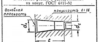
Specialties related to construction, architecture, mechanical engineering, design and others require students to be able to make drawings, read them and use special symbols. Undoubtedly, a lot depends on the specialization and the object that needs to be presented. Agree, there is a significant difference between the master plan of a site for the production of ceramic tiles and a complex section of a crankshaft. Collectively, the designations in the drawings include:
- Letters , which reflect conventional quantities, such as center distance, width, perimeter, diameter, height, depth, spring coil pitch and much more. To indicate massive and extensive sizes, it is recommended to use capital letters.
- Digital , which indicate exact dimensions, angular deviations, and the like.
- Alphanumeric , mainly found in drawings of electrical installations and have a positional designation
- Graphic, which can be used to designate anything: both the material of the product (abrasive, iron, wood) and structural elements (window, door, staircase).
Types of form tolerances
The resulting shape of the part is compared with its calculated parameters based on the allowable errors. They are called form tolerances. The values of this parameter are indicated in the drawings using two parameters: the tolerance field and the so-called base. A field is considered to be a space area allocated around the product. It includes all points on the surface of the product located at an approved distance. The base is chosen to be an element of the product that can be used as a standard for subsequent comparison.
Changes in shape include the following deviations of geometric parameters:
- straightness (how long the straight shape is maintained without deviating from a given direction);
- planes (maintaining the shape of the plane along the entire surface of the part);
- roundness (constancy of the circle radius);
- cylindricity (maintaining a cylindrical shape);
Shape tolerance allows you to determine with what accuracy the part must be processed. This will allow for proper further assembly of the entire unit.
Form deviations and tolerances
Strict adherence to the specifications of the configuration specified in the technical specifications is necessary to ensure its high performance. Deviations from the required parameters are specified in the form of established errors. With their help, the final shape of the product is determined. The specified parameters determine the allowed maximum and minimum values that are allowed after processing. These deviations are united by a common field.
Types of drawing documentation
To meet the needs of numerous types of activities, certain types of graphic documentation with their own symbols have been developed. The most common ones are:
- Architectural and construction drawings. They depict a building or its parts in order to give a complete picture of architectural and planning solutions, structures, materials used for the main elements. Architectural and construction drawings can show facades (views of a building from the front, back, left or right), plans (projections of sections with horizontal planes. Most often, the section runs along window or door openings, or at a height of 1/3 of the floor being drawn), sections (usually the entire division is made by a vertical plane).
- Mechanical engineering. Designed for main or auxiliary production in mechanical engineering. Depending on what objects are depicted on them, they are divided into drawings of parts, assembly drawings, general views, dimensional drawings, and installation drawings.
- Topographical. They serve to transmit data about the area. They depict populated areas, artificial and natural objects, residential and industrial buildings, roads (including those being designed), pipelines, and power lines. Performed in the form of maps, plans and sections.
Definition 1
A topographic map is a reduced-scale image of a fragment of the earth's surface.
Definition 2
If a map is drawn to a certain scale, it is called a plan.
- Engineering communications. Usually prepared during construction or reconstruction of objects. Such drawings help to quickly commission and ensure uninterrupted operation of the equipment in the future. Separate documents are prepared for each type of network (electricity network, heating network, etc.), external and internal communications.
- General plans. A special feature is the combination (overlay) on one sheet of a topographical, engineering-topographical or photographic plan of the area and the actual drawing of the designed object.
Definition 3
A master plan is a project document in accordance with which planning, development, reconstruction and other urban development of the territory are carried out.
- Electrical circuits. These diagrams indicate the connections between the components of devices whose operation is ensured by the flow of electricity. Diagrams are needed to connect the installation and troubleshoot the circuit.
Types of location tolerances
Compliance with all dimensions and permitted deviations indicated on the working drawings determines the high-quality and durable operation of the assembled unit. For this purpose, location tolerances are set. They determine the relative orientation and distances between individual planes of adjacent parts. These include the following parameters:
- parallelism and perpendicularity;
- the angle of inclination formed by the surfaces of two adjacent parts;
- coaxiality (stability of distances between shafts);
- axes intersection;
- symmetry (the degree to which the symmetry of one part of a part is maintained relative to another).
Location tolerance is necessary when assembling individual parts installed in a finished unit. It is divided into two categories: dependent and independent.
Deviations and location tolerances
Its correct and long-term functioning depends on the exact relative location of the individual parts. Ensuring correct assembly determines the location tolerance. It sets an acceptable limit on the parameters of adjacent surfaces. This restriction is set in a specially designated field. Deviations in the location of adjacent surfaces can be independent of each other.
Total tolerances
All types of permitted deviations are indicated for a specific part of the product. The marked data is summarized. The result obtained is called the total tolerance. This includes:
- parameters of various beats (radial, end);
- the resulting characteristics of the shape of the processed workpiece.
The final value is defined as the location of control points along a given straight line or higher order line.
Symbols on topographic diagrams
There are two types of topographic signs:
- Mandatory for use on all topographical diagrams.
- Used according to additional requirements of organizations for which drawings are prepared. Mostly such signs are used for specialized topographic surveys.
Figure 4. Topographic scheme
An important part of topographical diagrams is the points of the state geodetic network available on the area being drawn. A single coordinate system is used throughout the country. Each such point is indicated by marking the center and surface of the earth.
The next significant block is the designation of buildings, structures and their parts. For buildings, the material (graphically or alphabetically), number of floors, and purpose are indicated. Separate notes are provided for buildings under construction or destroyed.
Engineering systems are subject to designation - for example, power lines, underground utility hatches, pipelines, communication lines. Many symbols are provided for roads.
Natural objects are also drawn on topographic maps - coastlines, river beds, dry riverbeds, sandbanks, forests, etc.
Designations of tolerances of shape and location in the drawings
Each of the accepted parameters has its own individual graphic symbol. They are called shape tolerance or location tolerance. All approved by existing standards are presented in a unified system of design documentation. The shape tolerance and location tolerance are summarized in separate tables. They are divided into three groups. The first group includes deviations within the permitted field. The second group combines specific errors. The magnitude of which cannot be unambiguously determined during the measurement process.
The last group combines indicators that are standardized in special cases. This is due to the lack of existing graphics.
The required element is indicated by an approved graphic symbol. For its application, a special place is allocated on the drawing indicating footnotes and required values.
Where can I find a list of symbols?
There are several answers to this question.
Firstly, of course, reference books. Fortunately, they are produced for each specialty separately, and in the corresponding tables you can always find how to correctly designate the necessary element in your case.
Secondly, GOSTs. Here the situation looks more confusing, since you have to find the necessary notations yourself.
Thirdly, various methodological materials. Every university produces a variety of teaching materials designed to make life easier for even the laziest students. Only the essentials are collected in such materials.
Fourthly, the Internet. However, we highly recommend that you do not use this source, for several reasons. To begin with, it will take you a huge amount of time to search for a list of designations specifically for your specialty, and, of course, no one will guarantee that the presented designations are correct and error-free.
Dependent Tolerances
This category combines permitted deviations, for which they are allowed to be exceeded by a certain amount. The magnitude of this excess must correspond to the allowed parameter difference between the real surface and the selected base. The dependent location tolerance is calculated based on the developed formulas, based on the specified values. An alternative to this option is independent tolerance. Its value is always a constant value and does not depend on other parameters. Both types of deviations are indicated in the corresponding footnotes.
The order of reading drawings for beginners
In addition to drawings, a sketch is also widely used - this is not a technical drawing. This is a sketch of an object on an arbitrary scale, for the production of which no drawing tools are used, and it is not accompanied by inscriptions and dimensions. There are also no signs placed on it or next to it. The quality of the sketch depends on how close it is to the drawing.
Reading a drawing is a representation on a two-dimensional flat surface based on images of the three-dimensional shape of an object and its dimensions and containing other information.
But how to learn to read drawings correctly? Are there any simple, general principles for this?
Reading occurs in the following order:
- the main inscription of the drawing is readable;
- the main view is determined;
- types are analyzed and mentally combined into a single whole;
- The dimensions of the part and its components are determined.
Assignments of shape and location tolerances
The main provisions explaining the purpose of each of them are given in GOST 24643-81. Tolerances of the shape and location of surfaces allow you to choose a method, tool, and order for processing. In addition, tolerances of the shape and location of surfaces determine the operating conditions of individual products that make up a specific mechanism, its reliability and durability.
GOST 24642-81 Tolerances of shape and location of surfaces
1 file 789.93 KB
Numerical shape tolerance values
In the modern standard, 16 classes are approved for processing accuracy. Their numerical values increase from one class to another. The accuracy increases by 1.6 times. The standard defines three main levels, which are designated by capital letters of the Latin alphabet: “A”, “B” and “C”. Each level defines the following provisions:
- the first (letter A) is recognized as normal accuracy, which is at least 60% of the errors of all specified dimensions;
- the second geometric accuracy (letter B) belongs to the category of increased accuracy (usually it is equal to about 40% of the tolerances for all used parts);
- the highest degree of accuracy is the third level (letter C), which does not exceed 25% of all errors used.
Numerical values of tolerances for the shape of cylindrical surfaces are set for each of the three levels. According to the standard, they should not exceed 30% for the first level, 20% for the second and 12% for the third. This is due to the restrictions applied when deviating the radius of the product, by indicating the location of the established size.
Tolerances of flatness and straightness
Compliance with the plane parameters is assessed by comparison with the characteristics of the selected base. The base is a separate element of the part, which is clearly considered flat. The nature and location of the straight section is clarified based on the results of comparison with its base. Each of the allowed changes is indicated by a set icon. The footnote to this sign indicates the location and magnitude of the established deviation. The tolerance is set for lines and planes of different orders. All permitted size changes are combined into a single field. Generally recognized changes in the nature of straightness are convexity and concavity. The location and parameters of deviation from a given plane are indicated by the abbreviation (EFE). To describe the characteristics of straightness, the indicators included in a single set, designated (EFL), are adopted.
Tolerances for roundness and cylindricity of the longitudinal section profile
The concept of cylindricity refers to the similarity of a manufactured product with the parameters of a similar cylinder. Its diameter, length, location must correspond to those specified in the technical documentation. For comparison, select a cylinder with an adjacent (control) surface having a smaller diameter. It can be freely inscribed into the real inner surface. Established deviations from cylindricity make it possible to establish compliance of the processed part with a given shape. The location of these deviations determines the final appearance of the product and its installation location in the unit after assembly. This is the main difference from changes in the longitudinal section profile and the so-called roundness. They specify only one deviation parameter from points located on the workpiece. Deviation from the so-called roundness is understood as the greatest distance that specifies the location of points on the surface of the part in relation to the adjacent circle. By this circle we mean a circle with a large radius, circumscribed around the outer surface of rotation, with a minimum diameter that establishes the closest location between the points of these circles. The most common deviations are ovality and cut.
The magnitude of these changes is monitored using special measuring devices. These include: special templates, coordinate measuring machines, so-called “circularity gauges”.
Tolerances of perpendicularity, parallelism, inclination of axial runout
During the operation of the structural elements of the unit, which has a cylindrical shape, the effect of the so-called end runout is observed. The prevention of negative consequences is eliminated by establishing permitted deviations from the approved dimensions. These values are applied throughout the workpiece.
The tolerance establishes the magnitude and nature of the end runout. For some cases, its value is set relative to the largest diameter of the end surface located in the finished unit.
Tolerances for radial runout, symmetry, coaxiality, intersection of axes in diametrical terms
The manufacture of cylindrical products (shafts, rods, etc.) is always considered in the perspective of their further rotation relative to neighboring parts. To ensure their good performance, special forms of deviations are specified. These include three main types: symmetry of the location of adjacent surfaces, coaxiality, and the degree of intersection of the axes. In addition, two important parameters are set that determine the level of permissible runout. They determine the nominal diameter. Their values are specified in the drawing according to existing rules. The rotation axis is compared with a given base. In the absence of the specified base parameters, these parameters are determined relative to the element with the largest diameter.
Designation of coatings and heat treatments
The designation of the coating is indicated in the technical requirements of the drawing. Before designating the type of coating of a part, the word “Coating” is indicated in the requirement. If the same coating is applied to several parts, then the letter designation of the part to which the coating will be applied is indicated next to it.
If the technical process involves heat treatment, then the technical requirement indicates the hardness of the material obtained during its use. If only part of the part is processed, then this part is shaded with thick lines, the size of the surface to be processed is indicated, and the hardness of the material is indicated on the leader line.