INTERSTATE STANDARD
| Basic norms of interchangeability TRAPEZOIDAL MULTIPLE THREAD Basic norms of interchangeability. Trapezoidal multistart screw thread | GOST 24739-81 |
Date of introduction 01/01/82
This standard applies to trapezoidal multi-start threads and specifies nominal diameters, pitches, strokes and tolerances.
MAIN DIMENSIONS
3.1. The nominal diameter, stroke, pitch and number of thread starts must correspond to those indicated in the table. .
Table 1
Dimensions in mm
| Nominal thread diameter d | Step P | Number of visits n | |||||
| 2 | 3 | 4 | 6 | 8 | |||
| Row 1 | Row 2 | Thread stroke R h | |||||
| 10 | 1,5 | 3 | 4,5 | 6* | 9* | 12* | |
| 2 | 4 | 6* | 8* | 12* | 16* | ||
| 12 | 2 | 4 | 6 | 8* | 12* | 16* | |
| 3 | 6* | 9* | 12* | 18* | — | ||
| 16 | 2 | 4 | 6 | 8 | 12* | 16* | |
| 4 | 8* | 12* | 16* | 24* | — | ||
| 20 | 2 | 4 | 6 | 8 | 12* | 16* | |
| 4 | 8 | 12* | 16* | 24* | 32* | ||
| 24 | (2) | 4 | 6 | 8 | 12 | 16* | |
| 3 | 6 | 9 | 12 | 18 | 24 | ||
| 5 | 10 | 15* | 20* | 30* | — | ||
| 8 | 16* | 24* | 32* | — | — | ||
| (2) | 4 | 6 | 8 | 12 | 16* | ||
| 3 | 6 | 9 | 12 | 18* | 24* | ||
| 28 | 5 | 10 | 15* | 20* | 30* | 40* | |
| 8 | 16* | 24* | 32* | — | — | ||
| 32 | 3 | 6 | 9 | 12 | 18* | 24* | |
| 6 | 12 | 18 | 24* | 36* | 48* | ||
| 10 | 20* | 30* | 40* | — | — | ||
| 3 | 6 | 9 | 12 | 18 | 24* | ||
| 36 | 6 | 12 | 18 | 24* | 36* | 48* | |
| 10 | 20* | 30* | 40* | — | — | ||
| 40 | 3 | 6 | 9 | 12 | 18 | 24* | |
| (6) | 12 | 18 | 24* | 36* | 48* | ||
| 7 | 14 | 21* | 28* | 42* | 56* | ||
| 10 | 20* | 30* | 40* | 60* | — | ||
| 44 | 3 | 6 | 9 | 12 | 18 | 24* | |
| 7 | 14 | 21 | 28* | 42* | 56* | ||
| (8) | 16 | 24* | 32* | 48* | 64* | ||
| 12 | 24* | 36* | 48* | — | — | ||
| 48 | 3 | 6 | 9 | 12 | 18 | 24 | |
| 8 | 16 | 24 | 32* | 48* | 64* | ||
| 12 | 24* | 36* | 48* | 72* | — | ||
| 3 | 6 | 9 | 12 | 18 | 24 | ||
| 50 | 8 | 16 | 24 | 32* | 48* | 64* | |
| 12 | 24* | 36* | 48* | 72* | — | ||
| 52 | 3 | 6 | 9 | 12 | 18 | 24 | |
| 8 | 16 | 24 | 32* | 48* | 64* | ||
| 12 | 24 | 36* | 48* | 72* | — | ||
| 3 | 6 | 9 | 12 | 18 | 24 | ||
| (8) | 16 | 24 | 32* | 48* | 64* | ||
| 55 | 9 | 18 | 27 | 36* | 54* | 72* | |
| (12) | 24 | 36* | 48* | 72* | — | ||
| 14 | 28* | 42* | 56* | 84* | — | ||
| 60 | 3 | 6 | 9 | 12 | 18 | 24 | |
| (8) | 16 | 24 | 32* | 48* | 64* | ||
| 9 | 18 | 27 | 36* | 54* | 72* | ||
| (12) | 24 | 36* | 48* | 72* | 96* | ||
| 14 | 28 | 42* | 56* | 84* | — | ||
| 4 | 8 | 12 | 16 | 24 | 32 | ||
| 70 | 10 | 20 | 30 | 40* | 60* | 80* | |
| 16 | 32* | 48* | 64* | 96* | — | ||
| 80 | 4 | 8 | 12 | 16 | 24 | 32 | |
| 10 | 20 | 30 | 40 | 60* | 80* | ||
| 16 | 32 | 48* | 64* | 96* | 128* | ||
| 4 | 8 | 12 | 16 | 24 | 32 | ||
| (5) | 10 | 15 | 20 | 30 | 40 | ||
| 90 | 12 | 24 | 36 | 48* | 72* | 96* | |
| 18 | 36 | 54* | 72* | 108* | 144* | ||
| (20) | 40 | 60* | 80* | 120* | — | ||
| 100 | 4 | 8 | 12 | 16 | 24 | 32 | |
| (5) | 10 | 15 | 20 | 30 | 40 | ||
| 12 | 24 | 36 | 48 | 72* | 96* | ||
| 20 | 40 | 60* | 80* | 120* | 160* | ||
| 120 | 6 | 12 | 18 | 24 | 36 | 48 | |
| 14 | 28 | 42 | 56 | 84* | 112* | ||
| (16) | 32 | 48 | 64* | 96* | 128* | ||
| 22 | 44 | 66* | 88* | 132* | 176* | ||
| (24) | 48 | 72* | 96* | 144* | 192* | ||
| 6 | 12 | 18 | 24 | 36 | 48 | ||
| 140 | 14 | 28 | 42 | 56 | 84* | 112* | |
| (16) | 32 | 48 | 64 | 96* | 128* | ||
| 24 | 48 | 72 | 96* | 144* | 192* | ||
| 160 | 6 | 12 | 18 | 24 | 36 | 48 | |
| (8) | 16 | 24 | 32 | 48 | 64 | ||
| 16 | 32 | 48 | 64 | 96* | 128* | ||
| (24) | 48 | 72 | 96* | 144* | 192* | ||
| 28 | 56 | 84* | 112* | 168* | 224* | ||
| 8 | 16 | 24 | 32 | 48 | 64 | ||
| 18 | 36 | 54 | 72 | 108* | 144* | ||
| 180 | (20) | 40 | 60 | 80 | 120* | 160* | |
| 28 | 56 | 84 | 112* | 168* | 224* | ||
| (32) | 64 | 96* | 128* | 192* | 256* | ||
| 200 | 8 | 16 | 24 | 32 | 48 | 64 | |
| (10) | 20 | 30 | 40 | 60 | 80 | ||
| 18 | 36 | 54 | 72 | 108* | 144* | ||
| (20) | 40 | 60 | 80 | 120* | 160* | ||
| 32 | 64 | 96 | 128* | 192* | 256* | ||
| 8 | 16 | 24 | 32 | 48 | 64 | ||
| (10) | 20 | 30 | 40 | 60 | 80 | ||
| 220 | 20 | 40 | 60 | 80 | 120* | 160* | |
| (32) | 64 | 96 | 128* | 192* | 256* | ||
| 36 | 72 | 108 | 144* | 216* | 288* | ||
| 240 | 8 | 16 | 24 | 32 | 48 | 64 | |
| 22 | 44 | 66 | 88 | 132* | 176* | ||
| 36 | 72 | 108 | 144* | 216* | 288* | ||
| 12 | 24 | 36 | 48 | 72 | 96 | ||
| 250 | 22 | 44 | 66 | 88 | 132 | 176* | |
| (24) | 48 | 72 | 96 | 144* | 192* | ||
| 40 | 80 | 120 | 160* | 240* | 320* | ||
| 12 | 24 | 36 | 48 | 72 | 96 | ||
| 260 | 22 | 44 | 66 | 88 | 132 | 176* | |
| 40 | 80 | 120 | 160* | 240* | 320* | ||
| 280 | 12 | 24 | 36 | 48 | 72 | 96 | |
| 24 | 48 | 72 | 96 | 144 | 192* | ||
| 40 | 80 | 120 | 160* | 240* | 320* | ||
| 12 | 24 | 36 | 48 | 72 | 96 | ||
| 300 | 24 | 48 | 72 | 96 | 144 | 192* | |
| 44 | 88 | 132 | 176* | 264* | 352* | ||
| 320 | 12 | 24 | 36 | 48 | 72 | 96 | |
| 48 | 96 | 144 | 192* | 288* | 384* | ||
Notes:
1. Boxed steps are preferred.
2. The steps indicated in parentheses are not recommended for use when developing new designs.
3. A thread with a stroke value marked * has a lead angle of more than 10°. For this thread, it is necessary to take into account the deviation of the profile shape in accordance with clause 4.5.
4. Threads for which the numerical value of the stroke P
h, is not allowed. The helix angle of this thread exceeds 30°.
5. In technically and economically justified cases, it is allowed to use other values of nominal thread diameters in accordance with GOST 24738.
When choosing thread diameters, you should prefer the first row to the second.
3.2. The nominal dimensions of the outer, middle and inner thread diameters are in accordance with GOST 24737.
Multi-start thread cutting
Cutting requires compliance with certain rules on metal-cutting equipment. The operation requires precise observance of angular divisions at the moment of sequential transition from one step to another. This allows you to maintain the exact number of thread starts.
Cutting is done in the following ways:
- gradual rotation of the fixed part at a given angle in the driving chuck;
- milling the product with disk or comb cutters (processing is carried out continuously or sequentially by dividing it into component parts).
The machine is adjusted not by step, as for a single-pass design, but by stroke size. In this case, the step and stroke determine the distance that the cutter or cutter must travel during one rotation of the workpiece. For example, to cut a three-start system onto a bolt with a diameter of 20 millimeters, the pitch size should be two millimeters. On machines equipped for such operations, special provisions are provided on the gearbox. Cutting a multi-start design with the specified parameters is done by setting the gearbox control lever on the headstock to a step with indices 2x3. On other machines, the stroke value is adjusted using a special step change unit.
After completing the first groove, the position of the second is calculated. For this purpose, the values of the full circle 360° are divided by the number of specified passes.
The obtained result allows you to determine the number of sectors and the angle through which you need to rotate the workpiece, re-fixing it in the spindle. Some machines are equipped with dividing devices to solve this problem. They allow you to accurately set the required angle. For example, to cut a three-start thread, it is turned clockwise by twenty divisions. For a four-start it is necessary to rotate 15 divisions. The greater the number of cuts required, the fewer divisions should be set.
If such a device is not provided, use the holes provided in the spindle. They allow you to change the angle starting from 30° in variable increments of 15 and 30 degrees. They correspond to the most commonly used numbers of entries from 12 to 2.
BASIC PROVISIONS OF THE PERMISSION SYSTEM
4.1. The thread tolerance system provides:
- thread diameter tolerances;
— positions of tolerance fields for thread diameters;
— classification of make-up lengths;
— thread tolerance fields and their selection, taking into account make-up lengths and accuracy classes.
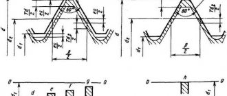
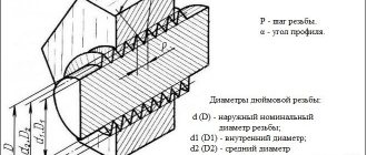
4.2. Schemes of tolerance fields for external and internal threads are shown in Fig. .
1
- nominal profile
Crap. 2
Deviations are measured from the nominal thread profile in the direction perpendicular to the thread axis.
4.3. Tolerances of thread diameters are established according to degrees of accuracy, indicated by numbers.
The degrees of accuracy of thread diameters are given in table. .
Tolerances for the average thread diameter are cumulative.
table 2
| Type of thread | Thread diameter | Degree of accuracy |
| External thread | d | 4; 6 |
| d 1 | 7; 8; 9; 10 | |
| d 3 | ||
| Internal thread | D 2 | 7; 8; 9 |
| D 1 | 4 |
Notes:
1. Accuracy degree 6 diameter d
can be used for threads produced by rolling.
2. Diameter accuracy degree d
3 must correspond to the degree of accuracy of diameter
d
2.
Diameter tolerances D
4 are not installed.
4.4. Diametric compensation of pitch deviations should not exceed 30% of the mean diameter tolerance to ensure uniform engagement of all threads.
This norm is not subject to mandatory control unless specifically stated.
4.5. For threads with a lead angle of more than 10°, the total tolerance does not include diametric compensation for deviations from straightness of the profile sides in the axial section.
By choosing the appropriate thread manufacturing method (for example, manufacturing convex thread flanks), the sides of the external and internal thread profiles must fit in their middle part.
4.6. The position of the thread diameter tolerance fields is determined by the main deviation (upper es for external threads and lower EI for internal threads) and is indicated by letters of the Latin alphabet (lowercase for external threads and capital for internal threads).
The positions of the tolerance fields are shown in Fig. , the main deviations are in table. .
Table 3
| Type of thread | Thread diameter | Main deviation |
| External thread | d | h |
| d 2 | With; e; g | |
| d 3 | h | |
| Internal thread | D 4 | H |
| D 2 | ||
| D 1 |
4.7. Make-up lengths are divided into two groups: normal N
and long
L.
4.8. The tolerance field of the thread diameter is formed by a combination of tolerance and basic deviation.
The tolerance field of an external thread is formed by a combination of the tolerance fields of the outer, middle and inner diameters.
The tolerance field of the internal thread is formed by a combination of the tolerance fields of the average and internal diameters.
4.9. Calculation formulas and rules for rounding numerical values of tolerances, main deviations and make-up lengths are given in the mandatory appendix.
Multi-start thread
One of the parameters that determines the type of thread is the number of starts. It varies depending on the degree of complexity of the problems being solved. One of the most technologically complex threads is multi-start thread. This number can be two, three, four or more (this is quite rare). The higher the value of this parameter, the more difficult it is to perform. The most complex and time-consuming to produce is the four-start thread.
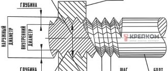
Regardless of the number, it has evenly spaced entries. They are placed at the same distance from each other, dividing the outer circumference of the part into an equal number of sectors. For example, a double-start thread will have two starts located symmetrically, one hundred and eighty degrees apart. For it, a stroke is the distance that is measured along the axis of the product (bolt, nut, shaft, etc.) between turns made in one pass, skipping other turns. With a single-pass, the concepts of step and move are identical; for a multi-pass, they have their own technical meaning. A move is always equal to a step multiplied by the number of moves made.
In addition to the number of starts, the type of multi-start thread is determined by the shape of the teeth being cut.
If the tooth has the shape of a classic trapezoid, it is called a multi-start trapezoidal thread. In cross section, a screw with a multi-start thread represents a figure with a given value of protrusions. Their number is equal to the number of sliced elements.
Using multi-start threads, the following problems are solved:
- increase joint strength (in many specialized joints);
- change the gear ratio (in gearboxes for various purposes);
- create a significant displacement of the nut along the propeller rod with a small number of revolutions made (for example, in the braking system of mine electric locomotives).
Multi-pass systems have the following marking sequence. The letter comes first. It means that it belongs to a specific type of thread: M - metric, UP or SP special multi-start. Next is a number that indicates the nominal diameter. After this number, the number of visits is noted, for example X2 means two visits. In parentheses, the number with the index “P” indicates the step value. For example, the marking of a multi-start thread M30X2 (P15) indicates that it is metric, with a diameter of 30 millimeters with the number of starts equal to two and a pitch of 15 millimeters.
For special types, the marking may look like Pack 22.5x(3x4.5). The first number 22.5 means the outer diameter, 3 indicates the number of passes, 4.5 indicates the pitch size. For a multi-pass design with such characteristics, the stroke value will be equal to the product of 3 and 4.5 mm, which is 13.5 mm. The number of passes can be determined visually by counting the number of turns on the end of a nut, screw or shaft.
According to the international designation system, the direction of the thread can be indicated: L - left, R - right. The multi-start thread itself is designated by the Latin letter S.
NOTATION
5.1. The symbol for a trapezoidal multi-start thread should include: the letters Tr, the nominal diameter of the thread, the numerical value of the stroke and in brackets the letter P and the numerical value of the pitch, the letters LH for left-handed threads.
An example of a symbol for a trapezoidal multi-start thread with a nominal diameter of 20 mm, a numerical stroke of 8 mm and a pitch of 4 mm:
Tr 20∙8
(
P4
)
The same, left:
Tr 20∙8
(
Р4
)
LH
5.2. The designation of the tolerance field of a multi-start trapezoidal thread consists of the designation of the tolerance field of the average diameter, i.e. a number indicating the degree of accuracy and a letter indicating the main deviation.
For example: 8e, 8H.
Tolerance range 4h diameter d
and the tolerance range 4H of diameter
d
1 is not indicated in the thread symbol.
In cases where for outer diameter d
If a tolerance field of 6h is assigned, then it is additionally indicated in the symbol of the thread tolerance field:
| For example: | 8e 6h |
5.3. In the thread symbol, the tolerance zone designation must follow the thread size designation.
For example:
Tr 20∙8
(
Р4
)-
8е
Tr 20∙8
(
Р4
)
— 8Н
Tr 20∙8
(
Р4
)
LH-8e
5.4. The make-up length, if different from the thread length, is indicated in millimeters at the end of the thread designation, for example:
(Changed edition, Amendment No. 1).
5.5. The fit in a threaded connection is indicated by a fraction, the numerator of which indicates the designation of the tolerance field of the internal thread, and the denominator indicates the designation of the tolerance field of the external thread.
For example:
Tr 20∙8
(
Р4
)
— 8Н
/
8е
Tr 20∙8
(
P4
)
LH-
8H /
8e
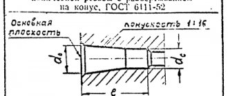
Conical inch thread with a profile angle of 60°
GOST 6111-52
Diameter from 1/16 to 2 inches
Symbol for 3/4" conical thread: K 3/4" GOST 6111-52
Interchangeable with inch conical American pipe thread NPT/NPTF (National Pipe Tapered) NPTF National Pipe Tapered Fuel - national pipe conical fuel thread. NPTF - sealed thread. Compaction occurs due to compression of the threads. Tapered fuel pipe threads are specified by ANSI/ASME B1.20.3 NPT tapered threads are specified by ANSI/ASME B1.20.1
TOLERANCES
6.1. Numerical values of diameter tolerances d
and
D
1 according to GOST 9562-81.
6.2. Numerical values of diameter tolerances d
2 and
D
2 must correspond to those indicated in the table.
, and diameter d
3 - in table. .
Table 4
| Nominal thread diameter d , mm | Step R , mm | External thread | Internal thread | |||||
| Degree of accuracy | ||||||||
| 7 | 8 | 9 | 10 | 7 | 8 | 9 | ||
| Tolerance, µm | ||||||||
| St. 5.6 to 11.2 | 1,5 | According to GOST 9562 | 335 | According to GOST 9562 | ||||
| 2 | 375 | |||||||
| St. 11.2 to 22.4 | 2 | 400 | ||||||
| 3 | 450 | |||||||
| 4 | 530 | |||||||
| St. 22.4 to 45 | 2 | 425 | ||||||
| 3 | 500 | |||||||
| 5 | 600 | |||||||
| 6 | 670 | |||||||
| 7 | 710 | |||||||
| 8 | 750 | |||||||
| 10 | 800 | |||||||
| 12 | 850 | |||||||
| St. 45 to 90 | 3 | 530 | ||||||
| 4 | 600 | |||||||
| 5 | 630 | |||||||
| 8 | 800 | |||||||
| 9 | 850 | |||||||
| 10 | 850 | |||||||
| 12 | 950 | |||||||
| 14 | 1000 | |||||||
| 16 | 1060 | |||||||
| 18 | 1120 | |||||||
| 20 | 1120 | |||||||
| St. 90 to 180 | 4 | 630 | ||||||
| 5 | 710 | |||||||
| 6 | 750 | |||||||
| 8 | 850 | |||||||
| 12 | 1000 | |||||||
| 14 | 1060 | |||||||
| 16 | 1120 | |||||||
| 18 | 1180 | |||||||
| 20 | 1180 | |||||||
| 22 | 1250 | |||||||
| 24 | 1320 | |||||||
| 28 | 1400 | |||||||
| 32 | 1500 | |||||||
| St. 180 to 355 | 8 | 900 | ||||||
| 10 | 1000 | |||||||
| 12 | 1060 | |||||||
| 18 | 1250 | |||||||
| St. 180 to 355 | 20 | 1320 | ||||||
| 22 | 1320 | |||||||
| 24 | 1400 | |||||||
| 32 | 1600 | |||||||
| 36 | 1700 | |||||||
| 40 | 1700 | |||||||
| 44 | 1800 | |||||||
| 48 | 1900 | |||||||
Table 5
| Nominal thread diameter d , mm | Step R , mm | Main diameter deviation d 2 | Nominal thread diameter d , mm | Step R , mm | Main diameter deviation d 2 | |||||||||||
| c | e | g | c | e | g | |||||||||||
| Degree of accuracy | Degree of accuracy | |||||||||||||||
| 8 | 9 | 10 | 7 | 8 | 7 | 8 | 9 | 10 | 7 | 8 | 7 | |||||
| Tolerance, µm | Tolerance, µm | |||||||||||||||
| St. 5.6 to 11.2 | 1,5 | According to GOST 9562 | 559 | According to GOST 9562 | St. 90 to 180 | 4 | According to GOST 9562 | 978 | According to GOST 9562 | |||||||
| 2 | 619 | 5 | 1100 | |||||||||||||
| St. 11.2 to 22.4 | 2 | 650 | 6 | 1174 | ||||||||||||
| 3 | 733 | 8 | 1328 | |||||||||||||
| 4 | 853 | 12 | 1585 | |||||||||||||
| St. 22.4 to 45 | 2 | 682 | 14 | 1680 | ||||||||||||
| 3 | 795 | 16 | 1775 | |||||||||||||
| 5 | 962 | 18 | 1875 | |||||||||||||
| 6 | 1074 | 20 | 1900 | |||||||||||||
| 7 | 1138 | 22 | 2013 | |||||||||||||
| 8 | 1203 | 24 | 2125 | |||||||||||||
| 10 | 1300 | 28 | 2250 | |||||||||||||
| 12 | 1398 | 32 | 2405 | |||||||||||||
| St. 45 to 90 | 3 | 833 | St. 180 to 355 | 8 | 1390 | |||||||||||
| 4 | 940 | 10 | 1550 | |||||||||||||
| 5 | 1000 | 12 | 1660 | |||||||||||||
| 8 | 1265 | 18 | 1963 | |||||||||||||
| 9 | 1343 | 20 | 2075 | |||||||||||||
| 10 | 1363 | 22 | 2100 | |||||||||||||
| 12 | 1523 | 24 | 2225 | |||||||||||||
| 14 | 1605 | 32 | 2530 | |||||||||||||
| 16 | 1700 | 36 | 2685 | |||||||||||||
| 18 | 1800 | 40 | 2725 | |||||||||||||
| 20 | 1825 | 44 | 2880 | |||||||||||||
| 48 | 3045 | |||||||||||||||
TOLERANCE FIELDS
9.1. The tolerance fields of external and internal threads established in accuracy classes (fine, medium and coarse) must correspond to those indicated in table. .
Table 6
| Accuracy class | External thread | Internal thread | ||
| Make-up length | ||||
| N | L | N | L | |
| Tolerance field | ||||
| Accurate | 7e, 7g | 8e | 7N | 8H |
| Average | 8c,8e | 9s | 8h | 9N |
| Rude | 9s | 10s | 9N | 9N |
Notes:
1. With increased accuracy requirements for make-up lengths L
to use tolerance fields established for make-up lengths
N.
2. Boxed tolerances are preferred.
9.2. Tolerance fields for external and internal threads indicated in table. , are a restrictive selection from the entire set of tolerance fields that can be obtained by various combinations of degrees of accuracy according to table. and main deviations according to table. .
Tolerance fields not provided for in the table. , are special. Their use is allowed in technically and economically justified cases, if the tolerance fields according to table. cannot meet the requirements for the product.
9.3. Limit deviations of external and internal threads corresponding to the tolerance fields established in table. , are given in GOST 9562 and in the mandatory appendix.
9.4. In landings, any combination of tolerance fields for external and internal threads established by this standard is allowed. It is preferable to combine tolerance fields of the same accuracy class.
Application
Trapezoidal threads, due to their braking properties and high friction force, do not require additional fixation. Thanks to this feature, it is actively used in lifting technologies. Most often, trapezoidal threads act as a lead screw and drive for screw presses. It performs the following set of operations:
- feeding movements on lathes;
- control of movement of lifting devices;
- movement of products on assembly containers;
- movement of press structures in the vertical direction.
It is also used in the manufacture of machine tools and adjusting mechanisms. The main areas of application are automobile construction (production of devices for motor gearboxes), locomotive engineering (creation of braking devices for mine locomotives operating using electrical energy) and other industrial areas of mechanical engineering.
APPENDIX 1 Mandatory
CALCULATION FORMULAS ACCEPTED IN THE TOLERANCE SYSTEM FOR TRAPEZOIDAL MULTIPLE THREAD
Formulas for calculating the numerical values of tolerances of degrees of accuracy 4 - 9, the main deviations of make-up lengths, as well as rounding rules - according to GOST 9562.
Numerical values of tolerances of the 10th degree of accuracy for diameter d
2calculated using the formula
| , | (1) |
for diameter d
3- according to the formula
| . | (2) |
(Changed edition, Amendment No. 1).
