16K20 - basic machine of normal accuracy;
It should be remembered that in the process of technical improvement of 16K20 lathes, some changes may be made to their design. Therefore, when ordering spare parts, the following information must be provided:
- The model and serial number of the machine are indicated on the plate placed on the spindle head;
- It is advisable to purchase components (bearings, electrical equipment, etc.) according to the type or number printed directly on them indicating the basic data.
- If this is not possible, the type or number can be determined using the diagrams and tables in the manual.
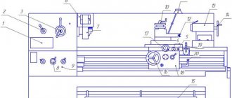
Controls of the machine 16K20
Controls of the machine 16K20.
- Feed rate table
- Thread type selection knob
- Spindle speed selection knob
- Emergency stop button
- Main motor start button
- Chuck protective screen
- Three jaw chuck
- Feed speed selector knob
- Feed box oil indicator
- 4-position tool holder
- Lamp
- Flywheel for moving the upper carriage
- Tailstock
- Tailstock quill feed flywheel
- Emergency stop pedal
- Longitudinal caliper feed flywheel
- Toolholder cross feed mechanism
- Caliper apron
- Longitudinal and cross feed handle with quick feed button
- Spindle rotation switch.
Design
Model 16B16KP was created on the basis of the previously produced lathe 1A616 and 16B16. Its positive characteristics are based on the design features of the lathe:
- Automatic transmission;
- smooth adjustment of cutting speed;
- high processing accuracy – precision;
- 2 busts are installed in the headstock;
- four-position tool holder with quick withdrawal mechanism;
- automatic selection of the optimal cutting mode due to the presence of an electric drive using thyristors.
Reference. The ergonomics of the machine – ease of use – have been significantly improved. The turner controlled all operations, making a minimum of movements.
Headstock:
On the right above the bed is the most complex component of the machine - the headstock. It contains nodes:
- gearbox;
- Transmission;
- spindle unit;
- splash lubrication system.
The oil simultaneously lubricates and cools the gears, washing away dirt and metal dust from them.
Important! The bearings are filled with grease during each maintenance inspection.
Guitar:
The gears located at the ends of the shaft and screw are located inside the headstock housing and are covered with a cover. Driven by V-belt transmission. The set of gears depends on the type of thread being cut.
Reference. When the guitar cover is opened while the machine is running, a lock is activated.
Caliper:
The support moves along the machine along the bed guides. It has mechanical driving modes: working and accelerated idle. On the apron there are handles for mechanical movement and manual supply of tools.
The slide with the tool holder moves along guides in the longitudinal and transverse directions. The simultaneous activation of feeds in 2 perpendicular axes is blocked by a device on the control handle.
Tailstock:
Located on the right side of the bed. It is attached to the guides with clamping strips and screws. A quill is installed inside the body, in the same axis with the spindle. It is moved manually by a handwheel located at the rear and clamped using a handle.
Morse quill cone No. 2. It states:
- center;
- drill;
- countersink;
- tap for cutting internal threads.
The tailstock moves along the guides manually. Fixed in place by straps located underneath. They are brought into working condition by a lever.
During adjustment, the quill is adjusted coaxially with the spindle using adjusting screws. The permissible displacement is less than 0.01 mm.
Apron:
The machine's running shaft and screw pass through the apron. Cam clutches with bevel gears convert torque into forward motion: forward and reverse motion of the caliper and carriage.
On the apron there are handles for controlling the caliper, slide, and switching cutting modes. The amount of displacement of the tool relative to the part is calculated from the divisions of the dial and vernier with an accuracy of 0.1 mm.
The movement of the caliper and slide forward and backward is started using the joystick. Its unit is equipped with a device for blocking the simultaneous activation of the working stroke in different directions. When you press the button in its handle, high speed is activated.
On the sides of the apron, above the guide, limit switches are installed. Having reached the extreme point, they are triggered and stop the caliper.
Gearbox:
The precise pitch when cutting threads is ensured by the lead screw. Its rotation, associated with a certain ratio with the revolutions of the part, is ensured by the feed box. It is located at the rear and rises above the headstock.
Transmission:
The gearbox is located at the bottom of the headstock, under the spindle assembly. It transmits torque to the drive shaft of the feed box.
Gearbox:
The automatic transmission is located at the rear of the headstock. She rotates the spindle. The presence in it of two searches: 1:4 and 1:16 increases the choice of the number of revolutions of the workpiece.
Principle of operation:
When you press the "Start" button, the engine is turned on. Through cam clutches, torque is transmitted to the drive shaft of the gearbox. It drives the lead screw through the feed box.
The spindle is driven through an automatic gearbox that transmits rotation from the output shaft of the gearbox. The speed of its rotation is controlled by a knob on the headstock. She, in turn, switches the gears of the search.
Cam clutches installed in the apron transmit movement to the caliper. At the same time, the tool holder with the tool moves with it.
Installing and removing the machine chuck 16K20:
- When installing and removing the chuck, protect the guides and bed with wooden boards placed under the chuck. Hold the chuck while you loosen the 3 cam locks by rotating ¼ turn counterclockwise. Align the A marks with each other. Carefully remove the cartridge.
- Before starting installation, you should make sure that there are no nicks on the mating surfaces and thoroughly wipe them with a lint-free cloth. Install the chuck onto the front end of the spindle. Clamp the cam lock of the clamping eccentric by rotating clockwise. The clamping eccentric mark A (Fig. 5) must be located between the 2 marks B (Fig. 5). The accuracy of the chuck fit on the spindle is checked by an indicator using a control band located on the outer cylindrical surface of the chuck body. Radial runout should not exceed 0.02 mm. Fig.5 Installing and removing the machine chuck 16K20.
- The fixed steady rest serves primarily to support long workpieces and ensures their reliable processing without vibrations; it is mounted on the frame using a fastening strip. *
- Install the steady rest crackers so that there is no gap between them and the workpiece and they do not pinch it. During processing of the part, it is necessary to lubricate the crackers well.
- The movable steady rest is installed on the longitudinal slide of the support and thus repeats the movement of the turning cutter. It prevents elastic deformation of long and thin workpieces under the pressure of a turning tool. When machining a workpiece, it is necessary to install the crackers in the same way as on a stationary rest.
Unpacking and transporting the 16K20 lathe
Fig. 1. Transportation diagram of the 16K20 lathe.
The lathe 16K20 is supplied on a pallet. When unpacking, care must be taken not to damage the machine with the unpacking tool. If upon unpacking you discover any damage that occurred during transportation, please notify the seller immediately. Do not operate the machine in this case.
Packing lists for accessories and tools are located in a separate box placed on the machine pallet.
Before transporting the 16K20 lathe unpacked, you must make sure that the moving components are securely fastened to the bed. The tailstock is fixed in the right extreme position, and the carriage is fixed in the middle part of the bed between the rope slings.
Transportation of the machine is carried out according to the transportation scheme (Fig. 1) using a four-line rope, ends 1 and 2 of which are put on two 60 mm steel rods. 3 (Fig. 1), inserted into specially provided holes in the base of the machine.
In places where the rope touches the machine, you need to install wooden spacers 4 (Fig. 1). When transporting to the installation site and when lowering it onto the foundation, it is necessary to ensure that the machine is not subjected to strong shocks and shocks.
Technical characteristics, description and passport 16K20
16K20 Screw-cutting lathe is a universal equipment for precise processing of metal products in full compliance with international quality standards. The objective advantages of machines of this type include convenient operation, wide functionality and excellent performance indicators, which guarantee high results and maximum efficiency when used correctly in repair, production and other metalworking enterprises. As a rule, screw-cutting lathes are used to perform technological operations of varying complexity with the external and internal surfaces of parts, including rotating bodies that have a varied axis profile. In addition, the 16K20 lathe is very often used for quick and convenient cutting of left-hand and right-hand threads (metric, inch, modular and pitch), fully meeting the needs of enterprises in all sectors of modern industry. The screw-cutting lathe 16K20 has an expanded package that includes all the necessary equipment to ensure successful operation:
- gearbox
- electrical cabinet
- feed box
- headstock
- chuck guard
- bed
- carriage and support
- apron
- caliper guard
- tailstock
Installation of machine 16K20
The longevity of maintaining the accuracy of the machine largely depends on the correct installation. The machine should be installed on the foundation according to the installation drawing (Fig. 2).
Rice. 2 Installation drawing of the foundation of the lathe 16K20
The depth of the foundation is taken depending on the soil, but must be at least 150 mm.
If the 16K20 machine is intended for finishing operations, the foundation depth must be at least 500 mm.
The machine is attached to the foundation with four foundation bolts with M24 threads.
When installing a 6K20 lathe, it is necessary to provide for the presence of free zones for opening the door of the electrical equipment cabinet and turning the sub-motor plate of the main drive electric motor, as well as for the possibility of dismantling the shields of the drive shaft and lead screw for cleaning and lubrication of the latter.
As an option, it may be proposed to install the machine at an angle of 10° to the wall of the workshop or equipment placement line.
Preparing the 16K20 machine for launch.
Alignment of the installation of the machine in a horizontal plane is carried out using a level installed in the middle part of the support parallel and perpendicular to the axis of the centers (the foundation bolts must not be tightened). In any position of the carriage, the level deviation should not exceed 0.04 mm per 1000 mm.
Having familiarized yourself with the instructions set out in the sections immediately following this, you can, in accordance with the sequence recommended below, begin preparing the 16K20 lathe for start-up.
Perform all operations related to preparing the 16K20 machine for startup, set out in section 6 “Lubricating the machine,” and fill the base chip collector located under the bed with coolant.
Connect according to the instructions in Section 7 “Electrical Equipment”. the machine to the grounding circuit and, after checking the correspondence of the network voltage and the electrical equipment of the machine, connect it to the electrical network.
After familiarizing yourself with the purpose of the controls (section, check by hand the operation of all machine mechanisms. The spindle rotation switch lever must be set to the neutral position.
You should be aware that due to the presence of locking devices, the 16K20 machine cannot be turned on:
- with the control cabinet door open;
- with the cover of replaceable gears open;
- with the cartridge guard cover folded back.
A description of blocking devices is placed in section 7 “Electrical equipment”.
By pressing the black “Start” button 5 (Fig. 4), turn on the main drive electric motor.
ATTENTION! It is imperative to check the operation of the centralized lubrication system of the spindle head of the 16K20 machine and the feed box using the oil indicator. If the oil indicator does not rotate, operation of the machine is unacceptable .
The operation of the lubrication pump can be monitored through a peephole located on the front of the headstock.
Using a switch, check the operation of the coolant pump motor.
After completing these operations, the machine is ready to start.
Machine design
The basis of the device is a durable U-shaped frame with 2 hardened, ground guides on top. It is installed on pedestals in a cast metal support, which is used as a trough for emulsion and collecting chips. The main electric drive is located in the cabinet on the headstock side of the product.
Dimensions of screw-cutting lathe 16K20
Machine dimensions: length 2505, 2795, 3195 or 3795 mm; width 1190 mm; height 1500 mm. The weight of the machine depends on its length and can be 2.835; 3.005; 3.225 or 3.685 per 103 kg.
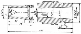
Spindle
The spindle shaft is steel with a through longitudinal hole through which a rod is passed, used as a workpiece, or a drift when knocking out the front center. To rotate the spindle in this machine, specialized precision rolling bearings are used. They are distinguished by high manufacturing precision and wear resistance, so they do not require periodic adjustments during maintenance during the operational period.
The shaft supports are lubricated by oil supplied to them under pump pressure. The front end of the spindle shaft is made in accordance with GOST 12593 - with a short centering cone 1:4.
Headstock
The headstock or headstock of the workpiece serves to fix one end of the workpiece and transmit torque to it. It houses the spindle, bulkhead box and other components. On the outside there are switching levers for the bulkhead box.
The output shaft of the headstock of the product is connected through gears to the feed reducer. The latter allows the slide to carry out the feed movement using the drive shaft during turning. Or by means of a lead screw for thread cutting. Which can be connected to the feed box without intermediate links.
Apron
This unit is necessary to move the caliper with the tool holder both along and across the axis of rotation of the part. It converts the rotary motion of the screw into linear displacement of the caliper. You can move the latter not only manually, but also by taking away part of the rotational torque from the spindle. The apron of this machine is equipped with a high-precision feed cut-off device on a stop, a design that has not been seen before.
Caliper
Designed to hold the tool holder with the cutter fixed in it near the workpiece. Possessing several degrees of freedom, it can move under the influence of the apron to form the desired surface character of the part with a cutter. To control the amount of movement, the unit is equipped with scale rulers with sighting devices that increase the accuracy and ease of reading readings.
Tailstock
She's a stubborn grandma. It is installed on guides that allow it to move along the machine. It has a tapered hole coaxial with the headstock output shaft. Which allows you to set a center to support the second end of the blank. Or a reamer, tap, drill and other similar ones for performing operations from the open end of the workpiece.
Headstock of lathe 16k20
The headstock contains the gearbox and spindle assembly. The spindle transmits torque to the workpiece through devices. For installation and centering of devices, a flange is used, a conical neck is used for installing cartridges, and a conical hole is used for installing centers. In lathes, this hole is made using a Morse taper. The front ends of the spindles are standardized (for lathes with flanged front ends of the spindles GOST 12593-81).
The guitar is used to adjust the feed chain using the selection of replaceable gears for cutting metric, inch, modular, pitch threads, as well as for adjusting the pitch (stroke) of the thread when cutting non-standard threads. In double-pair guitars, the distance L between the shaft I; shaft II is constant. A slope is freely mounted on shaft II, which is attached to the wall of the spindle head using a bolt.
Lathe apron 16k20
An apron is a mechanism for converting the rotation of a lead screw or lead shaft into translational movement of a caliper. The caliper receives translational movement from the lead screw through a split nut, and from the drive shaft through a series of gears through a rack and pinion gear.
This is interesting: TV-6 lathe - device, technical characteristics
Machine lubrication 16K20.
Correct and regular lubrication of the 16K20 lathe is of great importance for its normal operation and durability. Therefore, you must strictly adhere to the recommendations below.
When preparing the machine for startup, it is necessary to wash the filter mesh in kerosene, then, in accordance with the “Lubrication Card” and the lubrication diagram (Fig. 3), fill the reservoirs with lubricant and lubricate the mechanisms indicated in the card.
Lubrication should be carried out with lubricants specified in the lubrication chart, or their substitutes given in the “List of recommended lubricants” (clause 6.3).
Scheme
The basis and source of energy for any lathe is electric current. The 16K20 operating scheme is as follows.
16K20 Power supply circuit
The power supply and operation circuit of this machine is not original; all current is distributed evenly to the working “organs” of the unit in order to give it maximum power and excellent performance characteristics. Reasonable and rational distribution of energy throughout the machine allows you to perform work most productively, with optimal energy consumption. This is an important factor for any enterprise!
Machine lubrication map 16K20
| Headstock | Auto | I-20A GOST 20799-75 | Annually (approximately 700 operating hours) | Fill—1; drain—2 |
| Gearbox | Auto | I-20A GOST 20799-75 | Annually (approximately 700 operating hours) | Fill—3; drain—4 |
| Caliper apron | Auto | I-30A GOST 20799-75 | Annually (approximately 700 operating hours) | Fill—5; drain—6 |
| Bed guides | Auto, using apron lubrication system | I-30A GOST 20799-75 | 11 | |
| Cross slide, top slide | Manual | I-30A GOST 20799-75 | Weekly | 8,10 |
| Tailstock | Manual | I-30A GOST 20799-75 | Weekly | 9 |
| Replacement gears | Manual | CIATIM-203 GOST 8773-73 | Daily | 12 |
| Tool holder | Manual | I-30 AGOST 20799-75 | 1 time per shift | 7 |
List of lubricants recommended for lubrication of the 16K20 machine
| I-20A GOST 20799-75 | I-30A GOST 20799—75 | CIATIM-203 GOST 8773-73 |
| Viscosity at 50°C 17—23 cSt | Viscosity at 50°C 27—33 cSt | Effective viscosity at -30°C — no more than 1000 Pz |
| Flash point (in open crucible) — not lower than 165°С | Flash point (in open crucible) — not lower than 180°С | Corrosion test - withstands |
| Pour point - 30°C | Pour point - 15°C | Content of free alkalis in terms of 0.1% |
| Acid number - no more than 0.14 mg KOH/1 g oil | Acid number - no more than 0.2 mg KOH/1 g oil | |
| Ash content — no more than 0.007% Content of mechanical impurities - absent | Ash content - no more than 0.007% Content of mechanical impurities - absent | Free organic acid content - none Water content - no more than 2.5% |
| Content of water-soluble acids and alkalis - none | Content of water-soluble acids and alkalis - none | The content of mechanical impurities is no more than 0.25% |
| Water content - none | Water content - none | |
| Replacement with IGP-18 TU38-1-273—69 is allowed | Replacement with IGP-30 TU38-1-273—69 is allowed |
In the absence of lubricants specified in the list, it is permissible to use only those oils whose main characteristics correspond to those given.
Description of the lubrication system of the 16K20 machine
The 16K20 machine uses an automatic centralized lubrication system for the spindle head and feed box.
The pump, driven from the main drive electric motor through a belt drive, sucks oil from the oil bath and delivers it through a strainer to the spindle bearings and oil distribution trays. About a minute after turning on the electric motor, the oil indicator disk on the spindle head begins to rotate. Its constant rotation indicates normal operation of the lubrication system.
During operation, it is necessary to monitor the rotation of the oil indicator disk on the spindle head of the 6K20 machine. When it stops, you must immediately turn off the machine and check the filter. Remove the filter mesh elements in the plastic frame. Rinse each element in kerosene until completely clean. Do not blow out the filter elements with compressed air, as this may damage the fine mesh. After cleaning, assemble and install the filter.
ATTENTION! Filters must be cleaned before and after each oil change. In a new machine, it is advisable to clean the strainer at least twice a week for the first two weeks, and then once a month.
Every day before starting work, you need to check the oil level in the tank using the indicator and, if necessary, add it through the hole in the filler filter. When changing the oil, the reservoir is drained through a plug. Before filling the tank with oil, it must be cleaned and rinsed with kerosene.
The apron mechanism is automatically lubricated by an individual plunger pump. Oil is poured into the housing through hole 5 (Fig. 3), closed with a plug, and drained through hole 6 (Fig. 3). The oil level is controlled by the oil indicator on the front side of the apron.
The frame guides are lubricated using a centralized lubrication system of the caliper apron (repeatedly, depending on the intensity of use).
The guides of the transverse carriage, the upper carriage, as well as their lead screws must be lubricated using an oil can.
The carriage guides and cross slides are lubricated at the beginning and middle of the shift until an oil film appears on the guides.
Every day at the end of the shift, you need to remove the cutting head from the 16K20 lathe, clean its working surfaces and lubricate the conical axis of the tool holder.
Replacement gears and the axis of the intermediate replacement gear 12 (Fig. 3) are lubricated manually with CIATIM-203 GOST 8773-73 grease.
The support bushings of the replacement gears are lubricated using an oil can.
The remaining points are lubricated manually using the oil can supplied with the machine.
ATTENTION! The first oil change should be made a month after putting the 16K20 machine into operation, the second - after three months, and then strictly following the instructions of the lubrication chart.
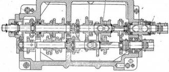
Design of the apron mechanism of the screw-cutting lathe 16K20
The apron mechanism is located in a housing screwed to the caliper carriage. From the running shaft, through a series of gears, the worm wheel and the wheel associated with it receive rotation. Both wheels sit freely on the shaft. From here the rotation is transmitted to the wheels, which sit freely on the shafts. These shafts are equipped with couplings with end teeth, which turn on the caliper feed in one of four directions.
The longitudinal movement of the caliper (to the left or to the right) is carried out when the clutches are engaged through the wheels, then through the wheel mounted on the bushing. The latter is connected by a movable key connection to a rack and pinion wheel, which transmits movement through the rack (not shown in the figure) to the caliper. The wheel can be released from engagement with the rack using a button. Transverse movement of the caliper (forward or backward) is carried out when the clutches are engaged. Then the movement of the gears is transmitted to the wheel, which sits freely on the bushing, and then to the caliper cross feed screw.
Shaft 1 carries a gear, which through the wheels imparts rotation to the disk and through it to the limb. Manual longitudinal movement of the caliper is carried out by a steering wheel through the wheels, bushing and rack and pinion.
Adjusting the apron mechanism of the machine 16K20
The force developed by the feed mechanism is regulated by turning nut 11. The amount of force is determined by a dynamometer, which must be installed between the rigid stop 47 (Fig. 28) and the carriage 19 (Fig. 27). Care should be taken to ensure that the amount of force does not exceed the permissible value according to the table. 1 (section 19).
The queen nut 62 mounted on the bracket 61 is adjusted at the factory.
If it is necessary to restore or replace a worn nut during repairs, you must use a special jig and tap, drawings of which can be sent upon request.
The backlash of the screw 20 of the drive of the transverse slide 11, which occurs when the nuts 22 and 23 are worn, is eliminated as follows.
The cover 12 is removed and the lock nut 15 is unscrewed using a drift (bit) made of soft metal. The clearance in the screw pair is selected by rotating the nut 14. The amount of the gap is determined by the dial 40 with a slight turn of the handle 33. The optimal value of the gap in the screw pair corresponds to the free play within one division of the limb. Then the locknuts 15 are tightened and the cover 12 is installed.
The rear tool holder 8, available as an option, is mounted on a cross slide, as shown in Fig. 27.
If, as the handle 4 wears out in the clamped position, it stops in a place that is inconvenient for the turner, then by grinding or replacing the spacer ring 1, you can set the handle 4 to the required position.
If the accuracy of fixing the tool holder 43 decreases, it is necessary to disassemble the cutting head and thoroughly clean the working surfaces of the mating parts. When crushing the tool holder, it is necessary to grind in the cones.
Setting the optimal gap between the carriage 19 and the strips 18, 64 and 66 is carried out by grinding the latter.
The clearance in the guides of the cross slide 11 and the cutting slide 9 is selected by tightening the corresponding wedges 52 and 42 using screws, the heads of which are located in the holes of the protectors 41 and 49.
For the convenience of determining the movement values of the cutting and cross slides when processing parts, the support is equipped with scale rulers.
On the cutting slide 9 there is a ruler with a division value of 1 mm.
The counting is carried out using the sighting device mounted on the rotating part 10 of the caliper.
On the carriage 19 there is a ruler with a division value of 10 mm by the diameter of the product, which is used to control the amount of movement of the transverse slide 11 using a viewfinder attached to them.
The design of the ruler mounted on the carriage provides for the installation of a rigid stop for transverse movements, supplied upon special order.
A rigid micrometric stop 47 for limiting longitudinal movements is mounted on the front shelf of the frame with two screws 82.
The machine model 16K20P is equipped with a support with a mechanical drive of the cutting slide (Fig. 29, 30), which can also be supplied with the machine model 16K20 upon special order. The mechanical movement of the cutting sled 9 is activated by pulling the button 122 toward you while holding the handle 129. The amount of feed of the cutting sled is equal to 1/4 of the longitudinal feed of the caliper.
Note. Numbers starting with 100 indicate parts that are specific to the mechanically driven tool slide support only. Numbers less than 100 are parts unified from a caliper with manual movement of the cutting slide (Fig. 27, 28).
Electrical equipment of the machine 16K20
To ensure high reliability in operation and maintenance of the electrical equipment of the 16K20 machine by semi-skilled specialists, all relay-contactor equipment and other electrical equipment have a simple design and have been tested over many years of operation in various conditions.
The electrical equipment of the 16K20 machine (with the exception of several devices) is mounted in a control cabinet located on the rear side of the machine.
The electrical equipment of the 16K20 machine is designed for connection to a three-phase alternating current network with a solidly grounded or insulated neutral wire.
The electrical connection and the power cables used must comply with regulations. The voltage and frequency in the electrical network must correspond to the data on the machine nameplate. The fuse should be 25A.
Use connecting cables only with the designation H07RN-F.
Electrical connections and repairs must be carried out by qualified electricians.
The electrical connection is made to the terminal blocks in the electrical cabinet at the rear of the machine.
Safety instructions
The 16K20 machine must be securely connected to the workshop grounding device (circuit).
The electrical resistance measured between the ground screw and any metal part of the machine that may become live as a result of insulation breakdown should not exceed 0.1 ohm.
IT IS STRICTLY PROHIBITED to work with an open terminal box and control cabinet!
A safety light-signal device is installed in the control cabinet, indicating the presence of voltage between the output terminals of the input circuit breaker and the neutral wire.
Modern analogues
It has already been mentioned that the plant stopped producing the 16 to 20 model, so the selection of machines with similar characteristics is relevant. Foreign manufacturers are famous for the D420x1000, Proma SPC-900PA, Jet GH-1640ZX DRO units.
Belarusian analogues produced at the Gomel plant offer 16VT20P-21. You can also note the TRENS models from the Slovak manufacturer SN 50 C and SN 500 SA.
They have a modern design and high-quality German components, with a relatively low cost for their characteristics.
Prices for goods from other manufacturers start from one and a half million to two, without calculating the delivery and installation of units.
Locking devices for electrical equipment of machine 16K20
The electrical circuit includes a lock that turns off the input circuit breaker when the control cabinet door is opened.
When the input circuit breaker is turned on, opening the cabinet door triggers the limit switch, which disconnects the electrical equipment of the machine from the network.
When the housing of the replacement gears is opened, a microswitch is activated, turning off the main drive motor.
The limit switch is mounted in the control cabinet, the microswitch is on the feed box housing.
For inspection and adjustment of electrical equipment under voltage (with the cabinet door open), the circuit provides a release switch installed in the control cabinet. This switch should only be used by qualified electricians.
Instructions for the initial start-up of the 16K20 machine
During the initial start-up of the 16K20 machine, it is necessary to check the reliability of grounding and the quality of installation of electrical equipment by external inspection. After inspection, disconnect the power wires of all electric motors at the terminal sets in the control cabinet and connect the machine to the workshop network using the input circuit breaker. Check the operation of all locking devices
- Using manual controls, check the precise operation of magnetic starters and relays.
- Once smooth operation of all electrical devices located in the control cabinet is achieved, connect the previously disconnected wires to the terminal sets.
- By alternately turning on the electric motors of the main drive and quickly moving the caliper, check the correct direction of their rotation.
- After making sure that the electric motors rotate correctly, you can begin testing the machine in operation.
Recommendations for servicing the electrical equipment of the 16K20 machine.
It is necessary to periodically check the condition of the starting and relay equipment of the 16K20 machine. All parts of electrical devices must be cleaned of dust and dirt. If carbon deposits form on the contacts, the latter must be removed using a velvet file or glass paper. To avoid rust, the interface between the core and the starter armature must be periodically lubricated with machine oil, followed by obligatory wiping with a dry cloth (to prevent the armature from sticking to the core). When inspecting relay equipment, special attention should be paid to the reliability of the closing and opening of contact bridges.
- The frequency of technical inspections of electric motors is set depending on production conditions, but not less than once every two months.
- During technical inspections, the condition of the input wires of the stator winding is checked, the motors are cleaned of contamination, and the reliability of grounding and connection of the shaft to the drive mechanism is monitored.
- The frequency of preventative repairs is set depending on production conditions, but at least once a year.
- During preventive maintenance, electric motors must be disassembled, internal and external surfaces must be cleaned, and bearing grease must be replaced.
- Under normal operating conditions, bearing grease should be replaced after 4000 hours of operation, and when operating the electric motor in dusty and humid environments - as necessary.
- Before filling with fresh grease, the bearings must be thoroughly washed with gasoline. Fill the chamber with lubricant to 2/3 of its volume. Recommended lubricants are given in table. 5.
- Preventive inspection of circuit breakers must be carried out at least once every six months, as well as after each shutdown due to a short circuit, including repeated ones.
- During inspection, you need to clean the switch from soot and metal deposits, check the tightness of the screws, the integrity of the springs and the condition of the contacts. The hinges of the switch mechanism should be periodically (after approximately 2,000-3,000 starts) lubricated with instrument oil.
ATTENTION! Do not make any adjustments to the switches under operating conditions. It was made by the manufacturer!
Equipment Specifications
The screw cutting machine has a wide range of technical features:
- The power of the electric motor ensures the functioning of the main drive and reaches 7.5 kW. And the drive itself, responsible for moving the caliper, has a power of 0.37 kW. The electric motor for the lubrication mechanism is 0.12 kW,
- the maximum length of the workpiece to be turned is 1.46 meters, and the maximum dimensions of the product fixed in the centers of the machine are 1.5 meters,
- Automatic transmission,
- thread cutting is carried out by the worker selecting a step, which is set by him based on the type of workpiece,
- the maximum cross-section of the workpiece turned above the bed should not be more than 40 centimeters, and above the support - 21 centimeters,
- the number of revolutions of the spindle device in forward motion is from 25 to 2500 rpm, and in reverse motion – from 25 to 1250 rpm,
- in forward movement, the spindle device has 21 speed levels, and in reverse – 18,
- the machine drive is from a 2-speed electric motor together with a gearbox and a bulkhead that programs 12 degrees of spindle speed in any of the 2 ranges,
- transverse feeds vary from 0.025 to 1.4 mm, and longitudinal feeds - from 0.05 to 2.8 mm per rotation,
- The range of movement of the caliper along the screw is 75 centimeters (lengthwise) and 22 centimeters (crosswise). The maximum distance of its movement along the roller is 50 centimeters,
- Rolling bearings create rigid and high-precision support,
- The guides of the carriages and the rolling pairs of the screws have impulse automatic lubrication,
- feed drive provides stepless feed adjustment,
- loading and unloading of parts is carried out manually.
These technical parameters enable the car to enjoy popularity even 50 years from the date of its release. The letters “K” and “P” in the name of the machine indicate that there is a copying mechanism and an increased degree of accuracy, respectively. The screw cutting machine is capable of operating from a mains voltage of 220, 380, 400, 415 and 440 V. It is characterized by a modern ergonomic structure and is easy to operate and control.
Dimensions and weight of the machine
The screw cutting machine is small in size and weight for a machine with similar functionality:
- width – 1110 millimeters,
- height – 1505 millimeters,
- length – 2270 millimeters,
- weight – 2 tons.
Purpose and scope
The 16b16kp machine is intended for performing various turning operations in centers, collets or in a 3 or 4-jaw chuck, for cutting various threads with a die or tap. Unlike most other brands, such a machine is intended for more thorough turning, and therefore is not recommended for roughing. It is usually installed in small repair shops. After processing on a lathe, the products are distinguished by excellent surface cleanliness.