Author of the article:
A threaded connection is the most common method of connecting parts when assembling mechanisms, machines, structures, industrial equipment, and various products. One of the important characteristics of a thread is the unit used to measure its parameters. According to this characteristic, they are available in metric and inch.
The differences between them are not limited to units of measurement, but also affect design characteristics. This leads to incompatibility of fasteners and parts with different types of threads, even if they appear identical in appearance. Therefore, it is necessary to have an idea of how metric threads differ from inch threads.
Inch thread parameters
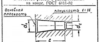
Requirements for standard parameters of cylindrical inch threads are specified in GOST 6111-52. Basic characteristics of threaded connections such as pitch and diameter are also indicated here.
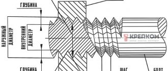
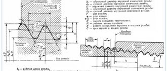
- The outer diameter is the distance between the top points of the threaded ridges on opposite sides of the pipe. To find it out, you can use a ruler or caliper.
- Internal diameter is the distance from one lowest point of the cavity between the threaded ridges to the other, located on the opposite side of the pipe.
Basic parameters of inch threads
Knowing the outer and inner diameters of an inch thread, you can calculate the height of its profile. To do this, it is enough to determine the difference between the diameters.
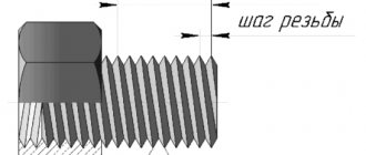
The pitch of an inch thread refers to the distance that separates two adjacent crests (or two adjacent valleys). The thread pitch usually does not exceed 3 mm, so high-precision rulers are used to measure it.
Measuring the pitch of an inch thread
Production: video
We have already talked about two cutting methods. Now let’s take a look at one of them, which you can do yourself at home:
In the article we wrote about conical and cylindrical inch threads. We provided tables, as well as calculation methods, talked about the features (parameters) of choice, and even gave a short historical summary. We hope this information was useful to you. To conclude, there is a video:
After you read the article, you can read about our products. for 15 years on the Russian market. During this time, we covered almost all cities of the country.
Sources
- https://martensit.ru/metizy/dyujmovaya-rezba/
- https://domxoloda.ru/table-sizes/
- https://www.rocta.ru/info/dyujmovaya-rezba-tablica-razmerov-shag-oboznacheniya-gost-i-markirovki/
- https://ipmet.ru/dyujmovye-rezby-razmery-tablica-gost-s-diametrami-i-shagom-oboznacheniya-v-mm/
- https://prompriem.ru/stati/dyujmovaya-rezba.html
- https://www.rinscom.com/articles/dyuymovaya-rezba-osnovnye-otlichiya-ot-metricheskoy-parametry-i-markirovka/
- https://Avto-bolt.ru/dyuymovaya-rezba/
- https://NpfGeoProm.ru/tehnologii/dyujmovaya-rezba.html
Differences between inch and metric threads
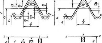
Metric and inch threads differ in the number of turns per thread pitch and different angles of inclination at the apex. For inch threads it is sharper and equals 55 degrees. The rest of the differences come from this.
- Due to the sharper angle of inclination, the profile of the threaded ridges changes. Inch joints have longer ridges but are less wide. The metric profile has more balanced ridges in shape (wider and not as long).
- Due to the difference in profiles, it is not possible to connect parts with metric and inch threads. The fasteners will be very fragile and leaky, which may lead to leakage of liquids during transportation.
Differences in the profile of imperial, metric and pipe threads
What is a thread gauge?
The thread gauge consists of a set of toothed combs, each of which has a certain distance between adjacent protrusions corresponding to the thread pitch. All combs rotate on axes fixed in the housing. The ground surfaces and configuration of the dies allow them to be used freely when determining the pitch of internal and external threads. The body is stamped “M60” for metric thread gauges and “D55” for inch gauges. The thread pitch value is stamped on the front surface of each comb.
The dies are made from tool steels of type U7, 8ХФ or ХВ4 in accordance with GOST 5950-85, characterized by reduced hardenability but a low coefficient of thermal expansion, which makes it possible to accurately use thread gauges in a wide range of external temperatures.
The profiles of the measuring combs are designed in such a way that during measurement, not only the pitch of the thread is determined, but also the degree of filling of its profile, as well as the number of threads (turns) of the thread. The latter is important when parts with ground threads are used, which can sometimes be damaged by the grinding wheel.
Table of sizes of inch and metric threads
You can find out how the sizes of metric threads relate to the sizes of inch threads using the data in the table below.
Similar sizes of metric and various varieties of inch threads in the range of approximately Ø8-64 mm
Tightening torques
Tightening torques for UNC inch fasteners for SAE grade 5 and higher bolts and nuts are shown in the following table.
| Thread size, inches | m | N*m*lbf-ft** |
| 1/4 | 12± 3 | 9±2 |
| 5/16 | 25 ± 6 | 18± 4,5 |
| 3/8 | 47± 9 | 35 ± 7 |
| 7/16 | 70± 15 | 50± 11 |
| 1/2 | 105± 20 | 75±15 |
| 9/16 | 160 ± 30 | 120± 20 |
| 5/8 | 215± 40 | 160 ± 30 |
| 3/4 | 370 ± 50 | 275 ± 37 |
| 7/8 | 620± 80 | 460 ± 60 |
| 1 | 900 ± 100 | 660 ± 75 |
| 11/8 | 1300 ± 150 | 950 ± 100 |
| 1 1/4 | 1800 ±200 | 1325 ±150 |
| 1 3/8 | 2400 ± 300 | 1800 ± 225 |
| 1 1/2 | 3100 ± 350 | 2300 ± 250 |
*1 Newton meter (N*m) is equal to approximately 0.1 kgm. ** Pound-force-foot is the British and American equivalent of N*m.
Types of inch threads
Inch threads can be cylindrical or conical. With a cylindrical connection, the dimensions of the outer and inner diameters are maintained along the entire length of the spare part. The threaded pitch has a fixed size, and the number of threads is related to the pitch. Spare parts with such a connection are more durable and reliable.
With a tapered connection, the thread has a variable diameter. The most widely used threads are those with a tapering diameter, in which the diameter at the base is larger than the diameter at the tail of the spare part. Parts with a tapered connection are often double marked, indicating not only the initial but also the final diameter. Inch tapered threads are stronger and wear out more slowly, but they are more difficult to apply, and errors in the procedure can seriously deteriorate the quality of the connection.
Basic information
An inch thread is a type of threaded connection.
It is usually applied to concrete or reinforced concrete pipes, although if necessary it can be adapted to process other parts (bolts, screws, rods, electronic parts). This type of carving is widespread in the USA and Great Britain, but it is also used in many other countries (France, Germany, South Korea, Japan, Italy). In Russia, its rules are regulated using GOST standards, and the main regulatory document is GOST 6111-52. Basic technical characteristics of inch thread:
- External diameter. Represents the longest distance between two pipe points. To measure, you can use a ruler, calipers and any other equipment with marked marks.
- Inner diameter. The parameter reflects the longest distance between the highest points of the thread ridges. Standard equipment (rulers, calipers) is also used for measurement.
- Threaded pitch. Represents the distance between adjacent turns of a threaded connection. The thread pitch is usually no more than 3 millimeters, so high-precision rulers or indirect counting techniques are used for measurement.
Inch threads can be cylindrical or tapered. In the case of a tapered connection, the thread maintains the size of the outer and inner diameters along the entire length of the spare part. The threaded pitch has fixed dimensions, and the number of turns is directly determined by the pitch and the length of the diameter. Spare parts with a cylindrical connection are more durable, reliable, and versatile.
In the case of a tapered connection, the thread has a variable diameter. Typically, a tapering diameter model is used, where the diameter at the base is larger than the diameter at the end of the part. Tapered connections can be double marked, when not only the initial but also the final diameter is indicated. Conical inch threads are more durable, less likely to crack, and have an increased shelf life. However, it is more difficult to apply, and cutting errors can seriously degrade the quality of the joint.
Conversion table for inch to metric sizes
inch.inch.inch.inch.inch.inch.12341/81 1/82 1/83 1/84 1/81/41 1/42 1/43 1/44 1/43/81 3/82 3/83 3/84 3/81/21 1/22 1/23 1/24 1/25/81 5/82 5/83 5/84 5/83/41 3/42 3/43 3/44 3/47/81 7/82 7/83 7/84 7/8
| — | — | 25,4 | 50,8 | 76,2 | 101,6 |
| 3,2 | 28,6 | 54,0 | 79,4 | 104,8 | |
| 6,4 | 31,8 | 57,2 | 82,6 | 108,8 | |
| 9,5 | 34,9 | 60,3 | 85,7 | 111,1 | |
| 12,7 | 38,1 | 63,5 | 88,9 | 114,3 | |
| 15,9 | 41,3 | 66,7 | 92,1 | 117,5 | |
| 19,0 | 44,4 | 69,8 | 95,2 | 120,6 | |
| 22,2 | 47,6 | 73,0 | 98,4 | 123,8 |
Inch thread parameters
| Outer diameter of the connected pipe | SAE Thread Rating | UNF thread rating | Outer thread diameter, mm | Average thread diameter, mm | Thread pitch | ||
| mm | inch | mm | threads/inch | ||||
| 6 | 1/4»» | 1/4»» | 7/16»»-20 | 11,079 | 9,738 | 1,27 | 20 |
| 8 | 5/16»» | 5/16»» | 5/8»»-18 | 15,839 | 14,348 | 1,411 | 18 |
| 10 | 3/8»» | 3/8»» | 5/8»»-18 | 15,839 | 14,348 | 1,411 | 18 |
| 12 | 1/2»» | 1/2»» | 3/4»»-16 | 19,012 | 17,33 | 1,588 | 16 |
| 16 | 5/8»» | 5/8»» | 7/8»»-14 | 22,184 | 20,262 | 1,814 | 14 |
| 18 | 3/4»» | 3/4»» | 1»»-14 | 25,357 | 23,437 | 1,814 | 14 |
| 18 | 3/4»» | — | 1»»1/16-14 | 26,947 | 25,024 | 1,814 | 14 |
| 20 | 7/8»» | — | 1»»1/8-12 | 28,529 | 26,284 | 2,117 | 12 |
| 22 | 7/8»» | 7/8»» | 1»»1/4-12 | 31,704 | 29,459 | 2,117 | 12 |
| 22 | 7/8»» | — | 1»»3/8-12 | 34,877 | 32,634 | 2,117 | 12 |
| 25 | 1»» | 1»» | 1»»1/2-12 | 38,052 | 35,809 | 2,117 | 12 |
Copper conductors, wires and cables
| Conductor cross-section, mm | Copper conductors, wires and cables | |||
| Voltage, 220 V | Voltage, 380 V | |||
| current, A | power, kWt | current, A | power, kWt | |
| 1,5 | 19 | 4,1 | 16 | 10,5 |
| 2,5 | 27 | 5,9 | 25 | 16,5 |
| 4 | 38 | 8,3 | 30 | 19,8 |
| 6 | 46 | 10,1 | 40 | 26,4 |
| 10 | 70 | 15,4 | 50 | 33,0 |
| 16 | 85 | 18,7 | 75 | 49,5 |
| 25 | 115 | 25,3 | 90 | 59,4 |
| 35 | 135 | 29,7 | 115 | 75,9 |
| 50 | 175 | 38,5 | 145 | 95,7 |
| 70 | 215 | 47,3 | 180 | 118,8 |
| 95 | 260 | 57,2 | 220 | 145,2 |
| 120 | 300 | 66,0 | 260 | 171,6 |
Aluminum conductors, wires and cables
| Cross-section of current-carrying conductor, mm | Aluminum conductors, wires and cables | |||
| Voltage, 220 V | Voltage, 380 V | |||
| current, A | power, kWt | current, A | power, kWt | |
| 2,5 | 20 | 4,4 | 19 | 12,5 |
| 4 | 28 | 6,1 | 29 | 15,1 |
| 6 | 36 | 7,9 | 30 | 19,8 |
| 10 | 50 | 11,0 | 39 | 25,7 |
| 16 | 60 | 13,2 | 55 | 36,3 |
| 25 | 85 | 18,7 | 70 | 46,2 |
| 35 | 100 | 22,0 | 85 | 56,1 |
| 50 | 135 | 29,7 | 110 | 72,6 |
| 70 | 165 | 36,3 | 140 | 92,4 |
| 95 | 200 | 44,0 | 170 | 112,2 |
| 120 | 230 | 50,6 | 200 | 132,0 |
Inch thread sizes
OST 1260
| Nominal thread diameter in inches | |||||
| Thread diameter in mm | Thread pitch in mm | Number of threads per 1″ | |||
| outer d | average d | internal d | |||
| 3/16 | 4,762 | 4,085 | 3,408 | 1,058 | 24 |
| 1/4 | 6,350 | 5,537 | 4,724 | 1,270 | 20 |
| 5/16 | 7,938 | 7,034 | 6,131 | 1,411 | 18 |
| 3/8 | 9,525 | 8,509 | 7,492 | 1,588 | 16 |
| 1/2 | 12,700 | 11,345 | 9,989 | 2,117 | 12 |
| 5,8 | 15,875 | 14,397 | 12,918 | 2,309 | 11 |
| 3/4 | 19,05 | 17,424 | 15,798 | 2,540 | 10 |
| 7/8 | 22,225 | 20,418 | 18,611 | 2,822 | 9 |
| 1 | 25,400 | 23,367 | 21,334 | 3,175 | 8 |
| 1 1/8 | 28,575 | 26,252 | 23,929 | 3,629 | 7 |
| 1 1/4 | 31,750 | 29,427 | 27,104 | 3,629 | 7 |
| 1 1/2 | 38,100 | 35,39 | 32,679 | 4,233 | 6 |
| 1 3/4 | 44,450 | 41,198 | 37,945 | 5,080 | 5 |
| 2 | 50,800 | 47,186 | 43,572 | 5,644 | 4 1/2 |
OST 266
| Nominal thread diameter in inches | |||||
| Thread diameter in mm | Thread pitch in mm | Number of threads per 1″ | |||
| outer d | average d | internal d | |||
| 1/8 | 9,729 | 9,148 | 8,567 | 0,907 | 28 |
| 1/4 | 13,158 | 12,302 | 11,446 | 1,337 | 19 |
| 3/8 | 16,663 | 15,807 | 14,951 | 1,337 | 19 |
| 1/2 | 20,956 | 19,794 | 18,632 | 1,814 | 14 |
| 5/8 | 22,912 | 21,750 | 20,588 | 1,814 | 14 |
| 3/4 | 26,442 | 25,281 | 24,119 | 1,814 | 14 |
| 7/8 | 30,202 | 29,040 | 27,878 | 1,814 | 14 |
| 1 | 33,250 | 31,771 | 30.293 | 2,309 | 11 |
| 1 1/8 | 37,898 | 36,420 | 34,941 | 2,309 | 11 |
| 1 1/4 | 41,912 | 40,433 | 38,954 | 2,309 | 11 |
| 1 3/8 | 44,325 | 32,846 | 41,367 | 2,309 | 11 |
| 1 1/2 | 47,805 | 46,326 | 44,847 | 2,309 | 11 |
| 1 3/4 | 53,748 | 52,270 | 50,791 | 2,309 | 11 |
| 2 | 59,616 | 58,137 | 56,659 | 2,309 | 11 |
Unit conversion table
| Conversion of energy units | Conversion of pressure units |
| 1 J = 0.24 cal | 1 Pa = 1 N/m*m |
| 1 kJ = 0.28 Wh | 1 Pa = 0.102 kgf/m*m |
| 1 W = 1 J/s | 1 atm =0.101 mPa =1.013 bar |
| 1 cal = 4.2 J | 1 bar = 100 kPa = 0.987 atm |
| 1 kcal/h = 1.163 W | 1 PSI = 0.06895 bar = 0.06805 atm |
Inch thread cutting technology
Inch pipe thread cutting can be done manually or mechanically. Let's describe both options.
Method 1: Tapping by hand
Inch threads are cut manually using a tap (internal thread) or a die (external thread). Operations are carried out in the following sequence.
- The pipe is clamped in a vice, and the tool is fixed: if it is a tap, then in the driver, if it is a die, then in the die holder.
- The die is put on the end of the pipe, the tap is inserted into its lumen.
- The tool is screwed into the pipe or screwed onto its end by rotating a knob or die holder.
- If necessary, to achieve a more accurate result, the procedure for cutting inch threads is repeated several times.
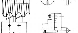
Method 2: Cutting threads on a lathe
The mechanical method involves cutting inch threads on a lathe. During the work you need to adhere to this algorithm.
- The pipe is clamped in a machine chuck, on the support of which a thread-cutting tool is installed.
- The end of the pipe is chamfered with a cutter, after which the cutting speed is adjusted.
- After bringing the cutter to the surface of the pipe, the machine turns on the threaded feed.
It is possible to cut inch pipe threads on a lathe only if the products have a sufficient reserve of rigidity and strength. The mechanical method guarantees an accurate and high-quality result, but requires great skills from the master.
Slicing methods
Inch threads can be applied to almost any cylindrical or conical parts. These could be pipes, bolts, special workpieces, and so on. Basic cutting methods:
- Hand cutting. With this processing method, cutting is carried out using a tap or die. The main advantage of the technology is the high mobility of the technique. The worker does not need to carry the workpiece to the cutting workshop - he can take with him all the necessary tools to perform the cutting on site. For cutting, it is recommended to fix the workpiece in a vice. Then you need to put a die on the end of the pipe or insert a tap into the inside of the pipe. After this, you need to turn the tool to create internal or external threads on the part. To make the job easier, it is recommended to use pliers or similar equipment. If necessary, manual cutting can be done in several passes (this will increase the quality of processing).
- Application of lathes. In this case, processing is carried out using a tapping cutter, which can be used to create external or internal threads. The machines are usually large in size and electrically powered, which makes them not very mobile. For cutting, the workpiece is fixed in the machine chuck, and the cutter is inserted into the support. After turning on the machine, the part is cut, and with the help of the caliper the speed of work and the direction of feed of the cutter are adjusted. Modern lathes can be equipped with a CNC panel, which allows you to automate a number of procedures and simplify the task for the worker.
Accuracy classes and rules for marking inch threads
Inch threads according to GOST can correspond to one of the accuracy classes: 1, 2 or 3. The letter A (corresponds to external thread) or B (internal) occupies the adjacent place with the number indicating the accuracy class. Note that the 1st class of accuracy corresponds to the coarsest threads, and the 3rd class is the most precise, and the most stringent requirements are imposed on them.
To understand what parameters a specific threaded element corresponds to, you need to understand the symbols that are printed on it. The label contains the following information:
- nominal inch thread size;
- number of turns per inch of length;
- group;
- accuracy class.
The marking is applied to the part itself or packaging with parts and is an alphanumeric code of the following type: T1 T2 X Y1 Y2 - Z.
This code is deciphered as follows.
- T1 - the parameter indicates the category of the threaded spare part and can have several values: M (metric thread), MK (conical), Tr (trapezoidal single-start), S (thrust single-start), G (cylindrical pipe).
- T2 - indicates the outer diameter of the spare part; for inch threads it is indicated in inches.
- X is a separator symbol that does not carry any semantic load, but is required to be applied according to GOST.
- Y1 is the width of the thread pitch, which is indicated in millimeters even on inch threads. In rare cases, a parameter may be indicated in inches, but then two notches are placed next to the number, which indicate that we are looking at inches.
- Y2 is the direction of the threaded screw. There is a left-hand thread, the parameter is designated as LH. If it's on the right, they let him through.
- - also refers to delimiter characters that separate the main part of the code from the Z parameter.
- Z is a parameter that indicates the thread accuracy class. Can take the form of designations 4k, 6h, 6E, 8G, 8D, etc.
An example of a symbol for an inch thread
Interpretation of inch thread markings
Let us look at the designation of inch threads in the technical documentation using the example of marking G 2” LH-2-40.
- G - indicates that the pipe thread is cylindrical.
- The number 2 indicates the outer diameter size in inches.
- LH - these letters indicate that the thread is left-handed.
- Number 2 informs about the accuracy class.
- The number 40 indicates the screw length.
Measurements
Despite the differences between metric and inch threads, their measurement is performed with the same tools:
- calibers;
- thread gauges;
- mechanical meters - micrometers, calipers.
Mechanical gauges can only be used to measure external diameter. Therefore, such instruments are used only for preliminary measurements.
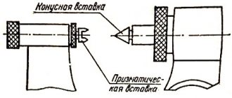
A convenient way to determine the pitch of an inch thread is to use a gauge. The same method can be used for metric cutting. The gauge is a fitting or coupling, on which an internal or external thread is cut, respectively, the parameters of which exactly correspond to the standard. The part with the thread to be measured is screwed into the gauge or screwed onto it.
If there are no difficulties and a tight connection is formed, then the measured pitch corresponds to the standard value indicated on the gauge. If the connection fails, you need to take a caliber with different parameters and try again. To carry out such measurements, gauges are used taking into account the difference between metric and inch threads.
The thread gauge further simplifies the measurement process. It is a set of plates with combs, the dimensions of which correspond to standard thread sizes. The plate is applied to the thread with a comb. Its profile must exactly match the thread profile. This allows us to say that the parameters of the latter correspond to the standard values indicated on the thread gauge plate.