Cutting modes for CNC machines
2016-09-02
Cutting modes for CNC machines used in practice depending on the material being processed and the type of cutter
Theoretical basis for choosing cutting modes on milling machines Spindle rotation speed, feed rate - all these are the basics of cutting. It is relatively easy to obtain information about this. You can find this information in any book on milling. Below is a brief synopsis of one of these books. The choice of cutter diameter for work is determined by two parameters - width and depth of milling.
Basic terms for selecting the correct cutting conditions
Spindle speed and cutting feed rate are some of the basic concepts when setting up cutting modes. This is the basis that is given in almost any specialized literature on working with cutting tools. Below is a brief summary of such information.
Z step is the thickness of the layer that the cutter will remove in 1 pass. Depending on the tasks, milling occurs in one or several passes along Z.
Cutting feed is the amount (usually expressed in millimeters per minute) of movement of the machine spindle along the X and Y axes.
Infeed feed is the amount (usually expressed in millimeters per minute) of movement of the machine spindle in the vertical plane, along the Z axis.
Feed per minute is the amount of movement of the spindle in millimeters in a time equal to one minute. Formula for calculation: feed per cutter tooth, multiplied by the number of cutter teeth and multiplied by cutter revolutions per minute.
Rotation frequency is the number of revolutions made by the spindle within one minute.
Step - the simplest option - show with an example. In general, this is the amount of tool displacement in mm or % during processing.
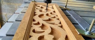
What a raster is in processing on a CNC router is clearly shown in the photo below.
What is a “step” in raster processing, schematically.
Cutting modes on a CNC machine
Cutting modes used in practice, depending on the material being processed and the type of cutter
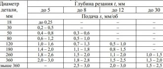
The table (given below) contains reference information on cutting mode parameters taken from practice. It is recommended to use these modes as a starting point when processing various materials with similar properties, but it is not necessary to strictly adhere to them.
It is necessary to take into account that the choice of cutting modes when processing the same material with the same tool is influenced by many factors, the main of which are: the rigidity of the Machine-Fixture-Tool-Part (AIDS) system, tool cooling, processing strategy, the height of the layer removed per pass and the size of the processed elements. General recommendations: - It is best to subject plastics obtained by casting to milling, because they have a higher melting point. -When cutting acrylic and aluminum, it is advisable to use a lubricating and cooling liquid (coolant) to cool the tool; the coolant can be ordinary water or universal lubricant WD-40 (in a can). -When cutting acrylic, when the cutter is adjusted (blunted), it is necessary to reduce the speed until the sharp chips start to appear (be careful with feeding at low spindle speeds - the load on the tool increases and, accordingly, the likelihood of breaking it). -For milling plastics and soft metals, the most suitable are single-flute (single-tooth) cutters (preferably with a polished groove for chip removal). When using single-thread cutters, optimal conditions are created for chip removal and, accordingly, heat removal from the cutting zone. -When milling, it is recommended to use a processing strategy in which there is a continuous removal of material with a stable load on the tool. -When milling plastics, to improve the quality of the cut, it is recommended to use counter milling. -To obtain an acceptable roughness of the machined surface, the step between passes of the cutter/engraver must be made equal to or less than the working diameter of the cutter (d)/engraver contact patch (T). -To improve the quality of the machined surface, it is advisable not to process the workpiece to its entire depth at once, but to leave a small allowance for finishing. -When cutting small elements, it is necessary to reduce the cutting speed so that the cut elements do not break off during processing and are not damaged.
Author: Denis Krasnokutsky
Date added: Jan 23rd, 2019
Author: Denis Krasnokutsky
Date added: Jan 23rd, 2019
SHARE ON SOCIAL NETWORKS:
return
Contact us 8-800-775-46-07 rus_777_ua s339933 Videos from customers
we are in social networks
“Twitte” 2010 - 2022 All information on the site is for reference only and is not a public offer in accordance with paragraph 2 of Article 437 of the Civil Code of the Russian Federation
Privacy Policy
If you find an error, please select a piece of text and press Ctrl+Enter.
Make a preliminary application
Complete a preliminary application for a loan at Tinkoff Bank
More information about installment/loan
1. You fill in the required fields, click on the “Submit” button
2. Our manager contacts you and helps you fill out the application correctly.
3. Next, a specialist will contact you and voice a solution.
4. All you have to do is sign the bank documents.
Requirements for the borrower:
1. passport of a citizen of the Russian Federation;
2. permanent registration on the territory of the Russian Federation;
3. age from 18 to 70 years;
4. having a permanent place of work.
Installment terms:
— Loan term – from 3 months.
— Loan amount – from RUB 3,000.
Russian
English French German Russian Spanish
General recommendations for cutting modes:
For soft wood (pine, larch, linden)
| Tool type | Working feed mm/min | Rotation speed (rpm) | Depth per pass |
| End 6mm | 2500-3500 | 20 000-24 000 | 7,5-8 |
| End 3mm | 1000-1500 | 20 000-24 000 | 4,5 |
| Engraver 30° * 0.2 | 800-600 | 20 000-24 000 | 3 |
For hard wood (beech, oak, plywood)
| End 6mm 3500 | 4500 | 20 000 — 24 000 | 34 |
| End face 3mm 2500 | 3000 | 20 000 — 24 000 | 2 |
| Engraver 30°x0.2 300 | 600 | 20 000 — 24 000 | 2 |
For two-layer plastic
| End 3 mm | 2000 | 12000 | 0.3 |
| Engraver 30°x0.2 | 2000 | 20000 | 0.3 |
For acrylic and polystyrene
| End 6 mm | 1000 — 1300 | 10 000 — 12 000 | 3 |
| End 3 mm | 800 — 1000 | 12 000 — 16 000 | 1,5 |
| Engraver 30°x0.2 | 300 — 500 | 18 000 — 20 000 | 0,30,6 |
For PVC
| End 6 mm | 1500 — 2000 | 12000 | 8-10 |
| End 3 mm | 1500 — 2000 | 12000-15000 | 4-6 |
Basic concepts about the operation of milling machines
Equipment can be completely different; the main classification depends on the plane in which the working area is located. In this regard, a distinction is made between vertical and more common horizontal frames. Accordingly, the location of the spindle and fasteners will be different. According to their specifications, there are universal (multifunctional) machines, as well as specialized ones, for example:
- to form smooth planes;
- for cutting figured grooves;
- gear cutting equipment (creating gear connections) and so on.
These were listed examples when working on metal. And for wood - manual, stationary, spindle and drum (they are very dangerous, so they are rarely used now, but they are very effective).
Separately, it is worth mentioning those machines that are equipped with a numerical control panel (CNC). They have the following advantages:
- Ease of operation: the operator does not need to make many movements, you can only observe and control the actions.
- The program independently calculates the optimal motion pattern and cutting mode during milling. This will be the shortest route for moving the cutter with maximum efficiency.
- Increased cutting accuracy. Here are the minimum permissible errors, which cannot be compared with those that occur during mechanical, manual processing.
Returning to simpler machines, let's see what main components it has:
- Bed. It is strong and should withstand almost any load. It includes a built-in gearbox. This block is designed to regulate the rotation of a vertically standing spindle, as well as the cutter that is mounted on it.
- Table with cross runners. Workpieces that are subject to longitudinal movement are attached to it. Also at the bottom there is an object responsible for feeding. It includes different handles to determine movements.
Versatility increases if a rotary table is present - there are more functions that can be performed on milling equipment. In addition, the highly versatile devices additionally have two spindles, which makes it possible to implement various milling technologies.
Innings
Another very important parameter that greatly determines the life of the cutter. Here's what depends on the selected mode:
- Thickness of the cut layer.
- Machine performance.
- Level of accuracy.
When choosing, very often milling cutters primarily pay attention to the recommendations of cutting tool manufacturers. Usually the following relationship works: the higher the feed, the lower the cutting speed. This is due to an increase in axial load. If you select a high level for both parameters at the same time, you may experience increased wear. Most often, the indicator is selected in the range of 0.1-0.25.
Milling width
This parameter does not always need to be entered manually. Usually it directly depends on the diameter of the cutter. Thus, it can be adjusted simply by choosing the “right” tool. For example, for the corresponding groove width. Accordingly, the higher the value, the larger the layer that is cut off at a time. As a rule, the service life of the tool also decreases with long operating times.
But due to the large milling width, it is possible to make a groove in one pass instead of two or more.
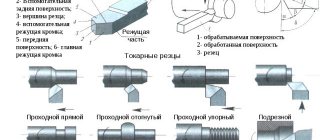
The classification of cutters depends on the purpose of cutting modes during milling
There are more than 1000 different types of cutters, which can be divided according to numerous parameters and sizes. Its choice directly depends on the rules of movement (rotation speed, direction, presence of counter feed and its power) of the tool. They are also directly determined by the type of metalworking - roughing or finishing. So, let's look at what classifications are carried out:
- according to the workpiece material - there are separate cutters for metal (different for different alloys), wood, plastic and other synthetic substances;
- in the direction of rotation - right-handed and left-handed, by the way, the ease of chip removal depends on this;
- according to design features - alloy, monolithic, folding with the ability to replace cutting parts, etc.;
- in shape - there is a lot of variety here, so listing them all is almost pointless; note that there are round, cylindrical, and conical disk cutters;
- according to the material of manufacture - it can be tool or high-speed steel, carbide metal, carbon or other alloys;
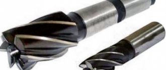
- by purpose - the largest division, which should include end, end, cutting, shaped, and so on.
When choosing the recommended cutting mode, you should especially pay attention to what material the cutting edge is made of, as well as what the cutter is intended for.
Cutting speed automated calculation formula
The cutting speed and the formula for its automated calculation will help determine the permissible cutting speeds for various pairs, such as corrosion-resistant and high-speed steel. If it is necessary to increase the cutting speed during turning , then a tool made of high-speed steel, despite its low speed range, is widely used when working with corrosion-resistant steels. It is widely used when it is necessary to produce turning tools, end mills, drills and other specialized tools due to its increased strength properties compared to carbide. At the design stage of a metalworking technological process in manual mode or in CAD TP mode, the technologist uses the recommendations of reference and regulatory literature in order to calculate the cutting speed , choosing an analytical or tabular calculation method. Attention should be paid to the fact that determining the cutting speed during turning for the same cutting conditions according to different reference books (see table) leads to a two- to three-fold discrepancy in its calculated value.
Most often this is due to the fact that various reference books use analytical calculations of cutting speed and give in them different values of the speed coefficient Cv in the formula for calculating cutting speed (1), which takes into account the values of the accepted tool life T, depth of cut t, feed S and correction factors coefficients determined by the properties of the tool Ku and the properties of the metal being processed Km.
V = (Cv / (Tm * tx * Sy)) * Ku*Km (1)
It should be noted that the correction factor Ku in formula (1) for the entire range of high-speed cutting tools P18, P12, P9, P6M5 and their modifications is assumed to be the same, equal to 0.3. Metalworking practice has noted that the cutting properties of different brands and different batches of high-speed tools differ from each other, and this difference is 25-45% or more.
In a number of reference books, it is recommended to determine the cutting speed during turning using tables and correction factors. Externally, this formula is more convenient for working in interactive mode with a CNC system, which is capable of containing in memory (ROM) arrays of data on the values of correction factors. In the tabular method, in order to determine the permissible cutting speed, there is formula (2):
Vd = Vt · Kv, (2)
where Vt is the tabular (matrix) value of the cutting speed, m/min; Kv - coefficient.
The problem with using this formula for automated calculation is that the cutting speed during turning will be determined using low reliability coefficients. As in the case of the speed coefficient Cv, the values of the initial (tabular) speed Vt are different in different sources, and the values of the correction factors included in it are also different.
Using tabular and analytical methods, it is difficult to accurately calculate the cutting speed, since they do not fully take into account the fluctuations in the properties of high-speed tools allowed by GOST, both between grades and within its grade composition, and fluctuations in the physical and mechanical properties of steel workpieces in delivery batches. This leads to errors in attempts to correctly assign the cutting speed during turning and, as a consequence, to a significant deviation of the actual service life period from the specified one.
The disadvantage of existing methods for determining the permissible cutting speed (for a given durability T, depth t, feed S and constant geometric parameters of the cutting tool) is that they a priori assume the constancy of the cutting properties of high-speed tools in delivery batches within their brand composition and the constancy of the physical and mechanical properties of a delivery batch of steel of a certain grade.
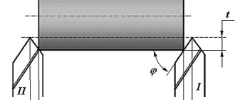
Table 1 shows the calculation of the cutting speed , as an example, of steel 12Х2Н4А with a high-speed tool using various reference and regulatory sources for selected conditions: cutter life T = 60 min, depth of cut t = 1 mm, feed S = 0.2 mm/rev using coolant. Cutter geometry: leading angle φ = 45°; auxiliary angle φ1 = 45°; rake angle γ= 5°; cutting edge inclination angle γ= 0°; clearance angle α = 10°; radius of curvature of the cutter tip r= 1 mm.
The content of elements in steel 12Х2Н4А С=0.12% Cr=2% Ni=4%. The letter A indicates high quality material.
Chemical composition: C - 0.09h-0.15%; MP - 0.3-0.6%; Si - 0.17-5-0.37; Сг - 1.25-5-1.65%; Ni - 3.25-3.65; P - 0.025%; S - 0.025%; Si - 0.3%.
Having physical properties T0.2 = 1080 MPa; TV - 1270
MPa; 85 = 13%; \|/= 60%; KSI - 105 J/cm2; HRC-39.
Analyzing the cutting speed during turning for the same turning conditions using various reference books shows that the discrepancies in the permissible cutting speed at the design stage of the technological process for turning corrosion-resistant steel can reach a factor of two or more.
Parameters for calculating cutting conditions
The main calculation of machining modes is based on three parameters: cutting speed (V), feed (S) and depth of cut (t). To obtain practical values of these parameters that can be used in production, at the first stage their calculated values are determined. Then, using empirical formulas, lookup tables and data from equipment data sheets, they are used to select technological cutting modes that will best suit the type of material being processed, the capabilities of the machine, as well as the type and characteristics of the tool.