Turning is the most common manufacturing technology for various parts and products, in which layers of metal of various sizes are removed from workpieces. This process is performed on special machines.
In this article we will talk about all the features of metal turning. You will learn:
- on what machines metal turning takes place;
- what products are made using this technology;
- what operations are performed;
- what tools are used for this;
- what features does metal turning have?
- how to prevent marriage.
Metal processing on lathes
Lathes are used for single, small-scale, serial and mass production of the following parts and products.
- Bushings.
- Shafts of various configurations.
- Nuts.
- Gears.
- Couplings.
- Rings.
- Pulleys, etc.
Photo No. 1: metal turning
Tool for auxiliary operations
This tool is used to install and fasten the cutting tool on the machine. It helps achieve precision and improve turning productivity. Its operating principles are the same for all lathes.
Only the shank, which serves to fix the device, is different in configuration.
Types of auxiliary tools:
- bayonet type holders;
- holders with a complex configuration and a cylindrical shank;
- prismatic holders with a cylindrical shank;
- cylindrical holders.
The supply of shafts and rods is limited, the turret head, which has a horizontal axis of rotation, and a set of special stops are deployed. They are made folding, adjustable, rigid.
Types of metal turning
There are the following types of lathes.
- Screw-cutting lathes. This is the most common group of lathes. They are most often used to process bodies of rotation for:
- giving parts a taper;
thread cutting;
- processing of external cylindrical surfaces;
- drilling, countersinking and reaming of holes;
- rolling corrugations;
- processing of ends and ledges;
- turning grooves;
- cutting off parts;
- cutting external and internal threads.
Image No. 1: main types of metal turning
Photo No. 2: screw-cutting lathe
Metal turning technology
The basic principle of metal turning technology is as follows. The fed tool cuts its cutting edge into the surface of the workpiece. The metal layer is removed and converted into chips. Let's talk about its types.
- Stepped. It is formed when processing workpieces made of aluminum alloys and medium-hard steels at medium speeds.
- Broken shavings. It is formed during turning of materials with low ductility.
- Elemental. Such chips are formed during turning of hard and low-viscosity metals.
- Merged. Formed during high-speed turning of workpieces made of soft materials. These include mild steel, lead, tin, copper, alloys based on them, and polymers.
Image No. 2: types of chips formed during metal turning
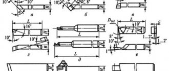
The main tool for metal processing on lathes
Cutters are most often used to process metal on lathes. Let us briefly describe their most common varieties.
- Straight through turning tools. Used for processing the external surfaces of workpieces. Three sizes of holders are most common.
- 20*20 mm.
25*16 mm.
- 32*20 mm.
Photo No. 3: straight through turning tools
Photo No. 4: thread cutter for cutting external threads.
Cutters designed for cutting internal threads have a curved shape.
Photo No. 5: thread cutters for cutting internal threads
Photo No. 6: parting turning tools
- For cutters designed for processing blind holes, this angle is 95°.
Photo No. 7: boring cutters designed for processing blind holes
Turning boring cutters designed for machining through holes have a 60° angle.
Photo No. 8: boring cutters designed for processing through holes
Photo No. 9: bent scoring cutter
Photo No. 10: thrust cutter
Photo No. 11: bent through turning tools
Modifiers for fastening parts on a machine
To secure workpieces in the working space of the machine, chucks with 2, 3 and 4 jaws are used. They can be with mechanized or manual clamping drive. The most popular is the self-centering three-jaw chuck (Fig. 6). Together with disk 4, cams 3, 2, 1 move synchronously.
Rice. 6. Three-jaw self-centering chuck: 1, 2 and 3 - jaws; 4 — disk; 5 - gear; 6 — cartridge washer
At one end of the disk, grooves are made in the shape of an Archimedes spiral. The lower projections of the cams are installed in the grooves. A bevel gear is cut out from the other end of the disk. It is in mesh with three bevel gears 5. By turning one gear 5 with a special universal wrench, disk 4 is forced to rotate as a result of gear engagement.
All cams of the cartridge move synchronously through the spiral along the grooves of the housing 6. There are only two directions of movement: the cams tend to the axis of the chuck, clamping the workpiece, or move away, releasing it. Structurally, the cams are made with three stages. They are hardened to resist wear.
The jaws can grip parts while machining the outer and inner surfaces. The fastener inside the workpiece provides for a technological hole into which the cams fit. Self-centering chucks with three jaws hold hexagonal and round parts, and round bars with a large cross-section.
Self-centering dual jaw chucks hold forgings and shaped castings. Only one workpiece is secured in the jaws of such chucks. In self-centering chucks, rods with a square cross-section are attached to four jaws. Chucks with individual adjustment of the jaws hold products with an asymmetrical or rectangular configuration.
Rice. 7. Types of centers: a - center with emphasis; b - reverse center; c - persistent half-center; g - with a sphere; d - corrugated cone; e - with a tip made of hard alloys; 1 - working part; 2 - shank; 3 - support protrusion.
The dimensions and shapes of the workpieces make it possible to use different centers during processing (Fig. 7). At the top of the center workplace the angle is 60˚ (Fig. 7, a). The conical surfaces of shank 2 and workplace 1 must be smooth, without nicks. Otherwise, when processing parts, it will cause error.
The cross-section of the supporting protrusion 3 should be smaller than the small cross-section of the shank cone. This proportion makes it possible to knock the tool out of the socket, leaving the cone of its working part intact.
When working with high loads and cutting speeds, rear centers of rotation are used (Fig. 8). An axle is pressed inside the tail part of the center 4 on rolling bearings 2, 3, 5. It ends with working part 1 extending outwards. This allows the axis to rotate with the workpiece during processing.
Rice. 8. Rotating center design: 1 - working surface; 2, 3 and 5 - bearing; 4 - shank.
To transmit rotation from the chuck to the workpiece fixed at the centers of the machine, clamps are used (Fig. 9). The clamp is placed on the part and tightened with screw 1 (Fig. 9, a). The shank 2 of the clamp should rest against the pin of the driving chuck.
Rice. 9. Turning clamps: a - simple: 1 - bolt; 2 — tail section; b - with self-tightening; 1 - thrust screw; 2 — tail part; 3 - spring plate; 4 - finger; 5 - prismatic body.
When a part is processed in the centers, the movement is transmitted to it by a driver chuck through a driver pin through a clamp tightened on the workpiece with a screw. Drive self-clamping chucks help reduce the roughing time for shafts with a cross-section of 15...90 mm.
The purpose of collet chucks is to fasten cold-drawn rods. They are also used for re-fastening parts on a pre-treated surface.
Diaphragm cartridges are used to obtain parts with high centering accuracy.
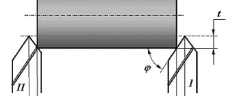
Rice. 10. Arrangement of workpieces in the chuck using rear center preload: 1 - workpiece; 2 and 3 - incisors
Methods of fastening and installation of workpieces on a machine are used based on their hardness, processing accuracy, and overall dimensions. If the ratio I/D<4, where I is the length of the workpiece, mm, D is the cross-section of the workpiece, mm, then the workpiece is secured in the chuck.
If 4 <10, the workpiece is secured in a chuck with pressure at the rear center or at the centers (Fig. 10). If I/D>10, then the workpiece is placed in the center or chuck. Fastening in the center of the tailstock and support with a steady rest is practiced (Fig. 11).
Rice. 11. Installation of steady rests: a - with movement; b - without movement: 1 - tilting mechanism; 2 and 3 - bolts; 4 - roller mechanism; 5 — clamping bar; 6 - nut with screw.
The most popular installation of the workpiece is considered to be in the centers of the machine. It is installed in the centers if it is necessary to give it concentric surfaces. If further processing is carried out on a grinding machine, also in centers. This must be provided for in the processing flow chart.
Parts that have holes are attached in the centers using turning mandrels (Fig. 12). Mechanized drives help to facilitate the work of the machine operator in the operations of securing parts on machines:
- magnetic;
- electrical;
- hydraulic;
- pneumatic.
Rice. 12. Turning mandrels: a - mandrel with small taper (usually 1:2000): 1 - center hole; 2 - clamp; 3 - mandrel; 4 - workpiece; b - cylindrical mandrel: 1 - workpiece; 2 - mandrel; 3 — pressure washer; 4 — washer; c - expanding (collet) mandrel: 1 - workpiece; 2 - conical mandrel; 3, 5 - nuts; 4 - hollow mandrel; g - spindle mandrel: 1 - collet; 2 - workpiece; 3 - expanding mandrel; 4 - cartridge; d - mandrel with an elastic shell: 1 - plan washer; 2 - bushing; 3 - workpiece; 4 — hole for introducing hydraulic plastic; 5, 6 - screw
How to prevent defects during metal turning and eliminate the consequences of errors
When turning metal, the following types of defects can occur.
- The roughness of the resulting surface does not meet the requirements specified in the drawing.
- The ground surface acquired an oval shape.
- The treated surface turned out to be conical.
- As a result of turning, a part with incorrect dimensions was produced.
- Part of the surface has not been treated.
- Let us consider the above types of marriage in detail.
The roughness of the resulting surface does not meet the requirements specified in the drawing
This happens for the following reasons.
- Feed rate set too high.
- Due to worn spindle bearings or improper mounting of the workpiece, it shakes violently.
- The gap between the individual parts of the caliper has increased.
- The cutter is not secured securely enough.
- The tool has a small radius of curvature.
- The cutter is poorly sharpened.
- The part material is too viscous.
- The cutter has incorrect geometric parameters
The above types of defects are most often eliminated by removing thin layers of metal.
The ground surface has acquired an oval shape
The workpiece may become oval due to spindle runout for three reasons.
- Uneven bearing wear.
- Uneven wear of the spindle journals.
- Small chips or dirt getting into the conical bore of the spindle.
These problems are solved by:
- regular checking of machines;
- timely equipment repairs;
- cleaning front centers and tapered holes.
The treated surface turned out to be conical
Most often this occurs when the rear center is displaced relative to the front. The cause of this problem is most often the entry of small chips or dirt into the rear hole of the quill. To eliminate this cause of marriage you need to:
- set the rear center correctly;
- clean the center and conical hole of the quill;
- move the tailstock housing on its plate (if necessary).
As a result of turning, a part with incorrect dimensions was produced
The dimensions of the received part most often do not correspond to the specified ones due to:
- inaccurate setting of cutting depth;
- incorrect measurement when removing test chips.
If the diameter of the part is smaller than required, then the defect cannot be corrected. In a radically opposite case, layers of metal of the required thickness are removed.
Part of the surface has not been treated
This type of marriage usually occurs for the following reasons.
- Incorrect initial dimensions of workpieces.
- Insufficient processing allowance.
- Poor straightening of the workpiece.
- Its installation is incorrect.
- Bad reconciliation.
- Inaccurate location of center holes.
- Rear center shift.
Usually such a marriage cannot be corrected. To avoid it:
- watch the location of the holes;
- always check that the rear centers are installed correctly;
- make sure that the workpiece is securely installed;
- set the required allowance values;
- measure workpieces before processing;
- straighten them carefully before fixing them in the machines.
Classification of turning tools
The quality and productivity of a turning operation directly depend on the condition of the cutter, the amount of longitudinal feed, speed and depth of cut. This defines:
- The rate of rotation of the machine shaft and the time spent processing the part.
- The durability of the cutter and the thickness of the removed metal layer.
- The nature and volume of chips formed during the passage of the working tool.
- Maintaining the lathe in good technical condition, eliminating extreme loads during operation.
The processing speed depends on the characteristics of the workpiece material, the type and quality of the cutters. The rotation speed depends on the parameters of turning parts and cutting speed. Cutters are divided into roughing and finishing. The former are used to remove large layers of metal, while the finishing ones are used to obtain a surface with specified roughness parameters. Depending on the direction of movement of the tool, it is divided into left, moving from the headstock to the tailstock, and right, moving in the opposite direction.
According to the shape and location of the cutting part of the incisor, they are divided into bent, straight and retracted. Depending on the purpose, the tool is classified into threading, cutting, shaped, through, boring, scoring and grooving.
Labor protection when performing turning work
- Wear safety glasses and earmuffs when working.
- Only use compressed air when tools are in contact with workpieces.
- Do not turn on the compressed air if the drive is not running.
- Before starting work, make sure that the
- casings;
- air hoses;
- compressed air supply systems.
mufflers;
- Before stopping the machine, turn off the feed;
remove the cutter from the part;
- start the spindle;
smoothly move the cutter towards the workpiece;
- cartridge;
faceplates;
Measuring tool
One of the most important and frequently used tools is a caliper. It is necessary to approach the choice of calipers with all responsibility; not only the convenience of work, but also your health depends on it. The latter relates to vision; a clearly printed scale and numbers make it very easy to work with the instrument and do not glare in the light.
I chose the caliper from the Chelyabinsk Tool Plant ShTs-2 with a division value of 0.05, produced in the USSR.
As a depth gauge I have a ShTs-1 with a circular scale. It completely covers the needs for measuring: boring depths, drilling, measuring groove depths and boring small diameter holes. Thanks to the dial scale, you can adjust it using a micrometer, and quite accurately bore small holes without using a bore gauge.
I also had electronic calipers, but good ones are expensive, cheap ones are afraid of water. When measuring readings with an accuracy of one hundredths, an error may occur, depending on the tension of the rod at the time of measurement. The effect is that everyone measures their own size.
Micrometers and bore gauge.
Here I would recommend having in your arsenal micrometers with sizes: from 0 to 25, from 25 to 50, from 50 to 75, from 75 to 100, the following sizes should be determined by the type of work being performed. For example, I also have a 300-325, but I only needed it once, and it’s been sitting idle for about 2 years. It’s a little easier with a bore gauge. I purchased a bore gauge from 50 mm, and thanks to the screw-on extensions, it covers the measured range up to 175 mm. You can measure and simply grind out a homemade extension. The exact dimensions less than 50 mm are based on homemade plugs. But you can also purchase a smaller bore gauge. See the specifics of your production.