We recommend purchasing:
Installations for automatic welding of longitudinal seams of shells - in stock!
High performance, convenience, ease of operation and reliability in operation.
Welding screens and protective curtains are in stock!
Radiation protection when welding and cutting. Big choice. Delivery throughout Russia!
General information
The surfaces of parts (both external and internal) are classified as shaped if they are formed by a curved generatrix, a combination of rectilinear generatrices located at different angles to the axis of the part, or a combination of curvilinear and rectilinear generatrices.
On lathes, shaped surfaces are obtained:
- manual or automatic transverse and longitudinal movement of the cutter feed relative to the workpiece with adjustment of the profile of the processed surface according to the template;
- shaped cutters, the profile of which corresponds to the profile of the processed part;
- using devices and copying devices that allow processing the surface of a given profile;
- by combining the methods listed above.
Shaped surfaces on long parts, the specified profile of which is obtained using a template, a copier and fixtures, are processed with pass-through cutters made of high-speed steel or carbide.
When processing fillets and grooves with a radius R < 20 mm on steel and cast iron parts, cutters are used, the cutting part of which is made according to the profile of the fillet or groove being processed.
To process fillets and grooves with a radius R >20 mm, the cutting part of the cutters is made with a rounding radius equal to (1.5… 2)R. In this case, both longitudinal and transverse movement of the caliper is used.
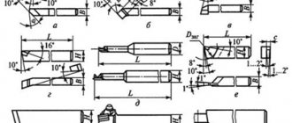
To increase the productivity of processing shaped surfaces of complex profiles, shaped cutters are used (Fig. 4.39). The width of shaped cutters does not exceed 60 mm and depends on the rigidity of the machine-device-tool-workpiece (WW) system and the radial cutting force.
Subtleties of the turning process
Separately, attention should be paid to turning shaped parts, when transverse and longitudinal feed is applied in parallel, carried out manually by the machine operator. This method of machining is used if it is necessary to produce a small batch of parts or the surface being processed is small in size. As for the first case, it is unprofitable to produce a conventional shaped cutter from an economic point of view, and to implement the second option, you may need a tool with non-standard dimensions, which causes difficulties in operation (for example, the formation of vibrations).
To remove the required layer of metal from the workpiece, either a finishing or a through cutter is used. The longitudinal slide moves to the left, and the transverse slide moves to the right and back. If it is necessary to process a surface characterized by small dimensions, then the longitudinal feed is realized by means of a support, which is installed in such a way that its guides are parallel to the center line of the equipment. Transverse feed in this case is carried out by the transverse slide of the caliper. The tool tip, regardless of the processing method, moves along a curve.
Processing parts with shaped surfaces is a rather complex task that requires certain skills and experience from the machine operator.
Highly skilled turners prefer to use automatic longitudinal feed, while simultaneously performing cross feed manually. These processes can be fully automated using special copying devices. Their use is especially important when processing large batches of parts. Go to list of articles >>
Machining with through cutters
With a small batch of workpieces and appropriate preparation of the worker, the shaped surface can be processed with a pass-through cutter with its simultaneous longitudinal and transverse movement, carried out manually.
When choosing a cutter, the shape of its tip and the location of the cutting edges should allow processing of a shaped surface with specified inclination angles and radii.
To acquire the skill of simultaneous longitudinal and transverse movement of a cutter along a given path, you should first (before processing a shaped part) perform several exercises, which will allow you to become familiar with the features of machine control during shaped processing. To do this, a finished part with a shaped surface of a complex profile is installed in the chuck or in the centers. When moving the caliper by coordinated rotation of its handles, make sure that the tip of the cutter moves in close proximity (with an equal gap of up to 1 mm) from the surface of the part.
Having made sure that the machine control is reliable, they proceed to processing the part with a shaped surface. In Fig. 4.40, a shows the sequence of processing the shaped surface of the handle blank using the described method. The workpiece is secured in a three-jaw chuck using surface A (Fig. 4.40, b), and the tail part of the handle, consisting of surfaces B, C, D, and E, is processed with a through cutter. Having installed the handle in the chuck along surface G (Fig. 4.40, c), the shaped part of the handle is processed. Using a scale on the machine bed, markings are made (along the axis of the workpiece) of the largest and smallest diameters of the shaped surface of the handle, and then the rough allowance is removed using a passing cutter in several passes (see the shaded areas in Fig. 4.40, c).
The final removal of the allowance (Fig. 4.40, d) is performed in several passes. First, carefully remove the scallops by smoothly moving the cutter along the axis of the workpiece and reciprocating the transverse slide of the caliper. Then a template with the profile of the finished part is applied to the non-rotating workpiece, the largest and smallest diameters of the shaped surface are measured and the places from which allowance must be removed are determined. To facilitate working conditions and increase productivity, experienced workers use automatic longitudinal feed, manually moving only the transverse slide.
To increase the productivity and accuracy of processing shaped surfaces with a pass-through cutter, a copier is used (Fig. 4.41). The shaped surface of the handle 2 is processed with a cutter 7, the transverse movement of which is carried out along the copier 5 by finger 4 in accordance with its profile. Together with pin 4, rod 3 and the associated support with the cutting head move in the transverse direction. In this case, the cross feed movement screw is disengaged from the cross support nut, and the longitudinal feed movement can be carried out automatically.
Shaped cutters: types and their features
A shaped cutter is a metal-cutting tool in which the shape of the cutting edge follows the profile of the finished product. The simplest version of such a tool is a rod cutter. Depending on the design features, such cutters can be:
- designed for turning concave surfaces;
- prismatic;
- disk
The first type of shaped cutters is characterized by simplicity and inexpensive production. At the same time, their cutting blade is ground down after several sharpenings. This manifests itself in a decrease in the height of the cutter in the center during installation, making the tool unsuitable for further work. It follows from this that rod cutters of this type are used in single or mass production.
For prismatic cutters, the role of the front surface is played by the end of the block used to make the tool, and their rear angle is formed as a result of the inclination of the cutter when fixed in the holder. Their advantages include the possibility of strong fixation on the machine, but their disadvantages include the complexity of manufacturing.
Disc cutters are characterized by a simple design, which simplifies the process of their manufacture. Their main advantage is that they are not drawn into the workpiece during the turning process, therefore, the metal product is of high quality.
Processing with shaped cutters
For processing fillets, threads and other shaped surfaces, shaped cutters are used. The profile of the cutting edge of shaped cutters completely coincides with the profile of the surface being processed, so the front surface of the cutter is installed exactly on the line of the centers of the machine. Shaped cutters are sharpened along the front surface. This must be taken into account when reinstalling the incisors. In the horizontal plane, the cutter must be installed perpendicular to the line of the centers of the machine; The correct installation is checked with a square, which is applied with one side to the cylindrical surface of the part, and the other to the side surface of the cutter, while there must be a uniform gap between the square and the cutter. The use of prismatic and round shaped cutters allows processing shaped surfaces with complex profiles.
Prismatic radial shaped cutters are mounted on a transverse support or in a turret with a horizontal axis of rotation. They are designed to work with cross feed motion. The cutting edge of the cutter must be installed in the center of the workpiece. Relief angles α are created by appropriate installation of the cutter in the holder, which is an advantage of this design.
Shaped round cutters with helical generatrices of the cutting edges provide lower roughness of the machined surface compared to round cutters with annular generatrices. Helical cutters are high-performance tools that are used on machines with turret heads.
The feed of the shaped cutter must be uniform and not exceed 0.05 mm/rev for a cutter width of 10...20 mm and 0.03 mm/rev for a cutter width of more than 20 mm. Feed depends on the rigidity of the part.
Turning of shaped surfaces
A shaped surface is a surface obtained either by a curved generatrix, or a combination of rectilinear generatrices, which are located at different inclinations relative to the axis of the part, or a combination of rectilinear and curved generatrices. These include helical grooves, spline and gear teeth, etc.
On lathes, a complex shaped surface can be obtained in four ways:
- by manually feeding the cutter (longitudinal, transverse) and adjusting the profile of the surface being processed using a template;
- through the use of feeds, as well as copiers and devices that allow the necessary processing to be performed;
- using shaped cutters that have a profile similar to the profile of the required part;
- By combining the above methods, the accuracy and productivity of parts processing increases.
Types of shaped cutters
A shaped cutter is a tool with a cutting edge that follows the profile of the surface being processed. Based on this, they distinguish:
- shaped cutters for a concave surface are a simple and inexpensive tool, the front surface of which, after several sharpenings, becomes unsuitable for further work. Grinding down the cutter plate has a negative impact on its installation: by reducing the height in the center, the tool becomes unsuitable for subsequent work. Consequently, shaped cutters are most suitable for single/batch production, when the profile of the required surface is not complex;
- Prismatic shaped cutters are a complex tool in terms of design. Its front surface is the end of the block used to make the cutter. The formation of a clearance angle is due to the location of the tool in the holder at an angle. For its fastening, a special ledge is provided - a dovetail, and a screw that provides the necessary rigidity;
- disc shaped cutters - their width, as a rule, does not exceed 40 mm (with the exception of tools up to 100 mm). To create the required clearance angle, the front surface of the cutter is placed a certain amount below its axis. A reduction of 1/10 of the cutting tool diameter results in a relief angle of approximately 12°. In most cases the rake angle is 0°. In this design, the manufacture of the cutter is significantly simplified, and during the work it is not pulled into the workpiece, which helps to improve the quality of processing.
Subtleties of processing shaped surfaces
To obtain a given profile of the workpiece being processed, attention should be paid to the installation of the cutter: the cutting edge should be located at the same level as the height of the centers of the lathe. The correct position when viewed from above is checked using a small triangle. One of its edges should be placed along the axis of the cylindrical surface of the workpiece, and the other should be brought to the side of the cutter. In this case, uneven clearance is not allowed between the tool and the square.
The rules for fastening shaped cutters should be followed with special responsibility.
As for feeding the shaped cutter, it is often done manually. In this case, its value depends:
- from the width of the cutting tool:
- at 10-20 mm the highest feed is 0.05 mm/rev;
- at 20 mm and above, the highest feed is 0.03 mm/rev;
- on the diameter of the workpiece - the smaller it is, the lower the feed;
- on the location of the workpiece area being processed relative to the chuck/tailstock - at the minimum distance it is recommended to select a larger feed than at the maximum.
Processing of shaped parts depending on feed
The simultaneous action of transverse and longitudinal manual feed is carried out in the case of turning relatively large shaped surfaces or when processing a small number of parts. If we use more traditional methods, then the first option would require a fairly wide cutter, which during processing would cause serious vibrations of the part, and for the second option, making a shaped cutter is generally impractical.
To remove the allowance, a through or finishing cutter is used. In this case, the longitudinal slide of the caliper is manually moved to the left, and the transverse slide, at the same time, is moved forward and backward. Relatively small shaped surfaces are processed as follows: longitudinal feed is carried out by engaging the upper slide of the support, the guides of which are located parallel to the center line of the lathe; transverse - by means of a transverse slide. In both cases, the trajectory of the cutting tool tip will be curved.
Correct observance of the ratio of longitudinal and transverse feed values during several passes will give the workpiece the desired shape. To do this kind of work well requires certain skills and experience. Qualified turners, when processing complex surfaces, turn on automatic longitudinal feed, while manually moving the transverse slide in parallel with it.
When turning large batches of parts, it is necessary to automate the complex movement of the cutting tool.
In order to cope with this task, copying devices are developed and manufactured. Nowadays, so-called “hydraulic calipers” are becoming increasingly popular and in demand. Go to list of articles >>
Using shaped cutters
It is advisable to produce parts of short length using cutters with a working edge that exactly matches the given contour. A prerequisite for accurate execution of technical cutting parameters is that the front surface of the cutting tool must be located at the level of the center line of the lathe. The front surface is used to sharpen cutters for shaping, which is important to consider if there is a need to install them repeatedly. You should check that the cutter is installed perpendicular to the center line of the machine - this condition significantly affects the quality and cleanliness of the cut. Perpendicularity is checked using a square, one edge of which is located in the direction of the axis of the part, the other along one of the sides of the cutter. The cross-section of the cutter body can be round or rectangular - this makes it easier to process surfaces with complex terrain.
The installation location for prismatic radial shaped cutters is a horizontal turret or a transverse support. The line of the cutting edge of the shaped cutter must be level with the center of the part fixed in the spindle or in the centers of the part. The dimensions of the clearance angles α can be set by adjusting the position of the cutter in the holder, which is quite convenient at the stage of preparatory work.
In metalworking industries, preference is, as a rule, given to cutters with helical generatrices of cutting edges compared to cutters in which the cutting edges are made in the form of ring generatrices. This is explained by the fact that the surface processed by cutters with a helical generatrix is less rough, while at the same time the cutting process occurs much faster.
The high performance of cutters with a helical cutting edge is fully exploited when they are installed in a turret. To improve cutting quality, a uniform feed of no more than 0.05 mm/rev is used with a cutter width of 10...20 mm. Wider shaped cutters (width greater than 20 mm) are designed for feed rates up to 0.03 mm/rev.
Obtaining a shaped surface using two feeds operating in parallel
Turning of shaped surfaces by parallel action of feeds (longitudinal, transverse) is most often performed in cases where it is necessary to process a small number of parts or the surface being processed has a large area. If we consider this example, then the use of other processing options is simply illogical. For example, making even the simplest shaped cutter for a small batch is a bad idea, since the cost of such products will increase significantly, and processing a large surface would require a too wide tool, the operation of which would cause strong vibrations.
To remove the allowance using the above technique, you will need a finishing/through cutter.
In this case, the longitudinal slide of the caliper moves to the left, and along with this movement, the transverse slide moves forward/backward. Go to list of articles >>