Geometric and kinematic accuracy
TO
category:
Metal cutting machines
Geometric and kinematic accuracy
Next: Thermal deformation and wear of cutting tools
Processing errors arising due to geometric inaccuracy of the machine. The types of errors that arise are determined, on the one hand, by the nature of the operation being performed, and on the other hand, by the nature of deviations in the relative position and shape of the guiding working bodies. For example, the plane of the milling machine table must be parallel to the plane passing through the axis of the machine spindle. If this condition is not met, the plane processed by the cylindrical cutter will not be parallel to the supporting surface. The plane in which the cross slide moves along the guides must also be parallel to the plane passing through the spindle axis, since otherwise the movement of the cross slide will lead to a change in the configured size that determines the distance between the table surface and the spindle axis.
Rice. 1. Errors arising due to geometric inaccuracy of the machine.
If the support guides are not parallel to the spindle axis, instead of a cylindrical surface, a conical surface will be obtained. If the rectilinear shape of the guides in the horizontal plane is distorted, distortions in the shape of the generatrix of the processed surface will occur.
Distortions in the shape of the circular motion guides also lead to a distortion in the shape of the machined surface. Thus, when the spindle neck of a lathe is oval, the circular guide line of the surface being machined takes the shape of an oval.
Processing errors can also arise if there are errors in the position of the seating surfaces that determine the position of the cutting tool or workpiece relative to the working parts of the machine. For example, if the axis 0101 of the conical centering hole is skewed relative to the axis 00 of the spindle, the part mounted on the mandrel, the outer surface of which is being machined, will take the shape shown in the drawing. If a tapered hole centers a cutting tool, such as a drill, then misalignment between the tapered hole and the spindle will increase the diameter of the hole being machined and may cause the cutting tool to break. The non-perpendicularity of the thrust end to the spindle axis leads to the transfer of the clamping chuck, and the runout of the centering shoulder 2 leads to the chuck runout. In both cases, processing errors occur.
For standard models of machine tools with a fixed layout, the geometric accuracy is standardized by the GOST mentioned above. When designing machines with an original layout and special machines, it is necessary to establish the position of the coordinate planes of the machine. If the machine has a rotating working element, then two coordinate planes, located mutually perpendicular, usually pass through the axis of the rotating working element, and the third one is perpendicular to this axis. One of the planes passing through the axis of the rotating working body is located parallel to the plane of movement of one of the working bodies making linear movements. If the machine does not have a rotating working element, then one of the coordinate planes is located parallel to the plane of movement of the working element performing a rectilinear movement, the second is perpendicular to it and parallel to the direction of movement of the working element, and the third is perpendicular to the first two.
After selecting the coordinate planes, the influence of errors in the location of guides, supporting surfaces and seats for installing workpieces, fixtures and cutting tools on processing errors is analyzed and standards for these errors are established. When establishing the permissible error value, one should be guided by the above GOSTs.
At the same time, methods must be developed to check the magnitude of errors that arise during the manufacturing and assembly of the machine.
Methods for checking geometric accuracy. When checking the geometric accuracy of rotating working bodies, the runout of the axis and the correct location of the supporting surfaces and seats are checked. If the spindle has a centering journal and a thrust collar for seating clamping devices, then the runout of the centering journal and thrust collar is checked. The runout of the centering journal is checked using an indicator, the pin of which rests on the centering journal. Since the movement of the indicator pin is the result of the combined effect of errors in the shape of the centering journal and its runout, the shape of the journal must first be checked.
Checking the runout of the thrust end is also carried out with an indicator, the tip of which rests on the end. The indicator shows the amount of total movement resulting from axial runout of the end and axial runout of the spindle. Therefore, the value of the axial runout of the spindle must first be established, which is checked using an indicator resting on a ball located on the axis
spindle and secured in a short mandrel. The amount of movement of the indicator pin depends on the combination of spindle movements and the runout of the end of the thrust collar and varies depending on the position of the polar angle of the point of contact of the indicator pin with the end. The test is carried out at several positions of the contact point. The end runout is defined as the algebraic sum of the largest indicator readings when checking the end and spindle runout.
The runout of the spindle's conical centering bore is checked using a precision cylindrical mandrel with a tapered shank. The mandrel is installed with a conical tail into the spindle hole. An indicator is used to check the runout of the mandrel at the end of the spindle and at a certain distance from the end of the spindle. Based on the obtained readings, the angle between the spindle axis and the axis of the centering hole is determined.
Rice. 2. Checking the straightness of the guides.
Straightness of guides. When checking the guides, their straightness in two mutually perpendicular planes and the parallelism of the different faces of the guides to each other are determined.
If the length of the guides is relatively short, their straightness can be checked using a control ruler. The ruler is mounted on guides on two tiles of the same size and the gap between the plane of the guide and the ruler at various points is determined using a set of tiles.
A precision level can be used to check the straightness of the guides in the vertical plane. The level is installed on a short slider, the shape of which corresponds to the shape of the guides being checked, and together with the slider it moves along the guides. By setting the level along the length of the frame in a series of positions with equal intervals between them, mark the angles of inclination of the guides in the corresponding sections on the level scale. Based on the data obtained, it is possible to construct a guide profile in the vertical plane.
The straightness of the guides in the vertical plane is also checked using a trench filled with kerosene. The mirror of the liquid filling the trench is horizontal. The gutter is placed along the guide. A short slide with a micrometric screw having a sharp conical end is moved along the guide. By rearranging the slider along the length of the frame into a number of positions with equal intervals between them, bring the sharp end of the micrometer screw into contact with the kerosene mirror and mark the error value for each position on the screw scale.
High accuracy and ease of testing are achieved using various optical instruments.
Checking the straightness of the guides in the horizontal plane can be done using a string and a microscope mounted on a slide or short slide. By moving the microscope along a string stretched under the action of a load, the magnitude of the guide error is noted on the microscope scale.
An autocollimator can be used to check the straightness of the guides in the horizontal and vertical planes. A short slide on which a metal mirror is mounted moves along the frame guides. A parallel beam of rays directed by an autocollimator falls on the mirror. The light source illuminates a translucent mirror, which directs a beam of light onto a grid with two mutually perpendicular scales located at the focus of the lens. The lens directs a parallel beam of light with a scale image onto mirror 6. The scale image reflected at an angle is projected onto the grid with a corresponding offset. Based on the shift of the scales observed in the eyepiece, the deviation of the guides in the vertical and horizontal planes from the given direction is determined.
When checking the relative parallelism of the guides, a short slide with an indicator mounted on it moves along one of the guides, and the indicator pin slides along the second guide.
Checking the relative position of the guides and spindle axes. The parallelism of the spindle axis guides in two mutually perpendicular planes is checked using a precision mandrel installed in the spindle, the axis of which coincides with the axis of the spindle and the indicator mounted on the movable working element. The indicator pin moves sequentially along the mandrel generatrices located in two mutually perpendicular surfaces.
After checking the parallelism of the guides, the parallelism of the table support surface to the spindle axis can be checked. This check is carried out using a stationary indicator, the pin of which rests on the surface of a ruler mounted on the table. When moving the table in the direction of the spindle axis, the indicator will show the amount of tilt of the table relative to the guides, and, accordingly, the spindle axis.
The perpendicularity of the spindle axis to the supporting surface of the table can be checked using an indicator mounted in the spindle. The indicator pin is in contact with the table surface. When turning the spindle, the indicator will show the deviation of the spindle axis from perpendicularity in two mutually perpendicular planes.
Checking the mutual perpendicularity of the guides is carried out using a square. A square is installed on the table, the guides of which must be perpendicular to the guides. Using a fixed indicator, the square is adjusted so that face 3 is parallel to the guides. The indicator pin rests on the edge and the square moves along the guides along with the table. The square must be aligned so that the indicator does not show deviations during movement. After aligning the square, the indicator pin rests on the edge of the square and the table moves along the guides. According to the indicator readings, the non-perpendicularity of the guides is judged.
The mutual perpendicularity of the guides can also be checked using a square. After checking that the table plane is parallel to the guides, a square is installed on the supporting surface of the table. When moving the console along the guides, a fixed indicator will show the amount of deviation from the perpendicularity of the guides.
Using methods similar to those described, you can perform all the necessary checks.
Kinematic accuracy. As mentioned above, during kinematic profiling, the source of errors that arise during the processing process may be errors in the transmission ratios of the kinematic chain, which carries out functionally related movements of the corresponding working bodies.
Rice. 3. Checking the relative position of the axes and guides.
Errors in gear ratios can be constant or variable. Constant errors arise due to the impossibility of accurately selecting the numbers of teeth of the gear wheels included in the kinematic chain. The impossibility of precise selection is due to the fact that the number of teeth that can be used is limited to a relatively narrow range of numbers: the minimum number of teeth is taken to be 20, and the maximum usually does not exceed 100-125, since as the number of teeth increases, the dimensions of the corresponding machine components increase.
The number of pairs of replaceable gears, the number of teeth of which are selected in accordance with the required gear ratio, usually does not exceed two. Thus, the possibilities for selecting the number of teeth are limited. The selection possibilities are further narrowed due to the fact that the set of interchangeable gears supplied with the machine does not include all the numbers available in the range from the minimum to the maximum values. In most cases, the selection methods discussed below make it possible to select with very high accuracy, however, in some highly accurate machines, additional correction devices are introduced to correct errors in the selection of replacement gears.
Variable transmission ratio errors may arise due to errors in the manufacture of kinematic chain elements. For example, when a gear runs out, the instantaneous gear ratio of the gear pair will change continuously.
Kinematic chains that carry out functionally related movements of the working parts of machine tools, in most cases, consist of gears. The last links in these chains are either a screw and nut or a worm gear. Therefore, when considering issues of kinematic accuracy, we will limit ourselves only to chains of this type, although in some cases in machine tools there are kinematic chains for carrying out functionally related movements, which also contain other mechanisms.
The instantaneous gear ratio of a gear pair is a function of a number of errors of the gear wheels included in this pair: runout of the initial circle, accumulated pitch error, profile errors, etc., which arise during manufacturing and during wear. The largest role is played by runout and accumulated pitch error. In works devoted to the issues of kinematic accuracy of gears, the joint influence of these errors is analyzed. However, GOST 1643-56 and GOST 1758-56, which standardize tolerances and deviations for various gears, establish a tolerance for the kinematic error of the wheel, which can be directly used when considering issues of the accuracy of kinematic chains.
When determining the error in the movement of the working element, it is also necessary to take into account the accumulated pitch error of the lead screw.
If the last link of the kinematic chain is a worm gear, then the error in the angle of rotation of the worm wheel shaft is determined. Using the formula, it is also necessary to take into account the kinematic error of the worm pair, which is determined by GOST 3675-56.
It should be noted that errors in the movement of the working body are mainly determined by the errors of the last link - the lead screw or worm pair.
Methods for checking kinematic accuracy depend on the nature of the movement of the working body. For linear movement, flat metal line measures, which are used in the reading devices of machine tools, can be used for this purpose. The line measure is set motionless, and a microscope is fixed to the movable working element. Replacement gears are selected in such a way that during one revolution of the shaft the working element moves by one mm. Using the microscope scale, errors in the actual movement of the working body are determined.
To check the kinematic accuracy of machines designed to form helical surfaces, a high-precision reference screw is used. The screw is installed between the centers and receives rotation from the machine spindle. The screw imparts movement to the nut, which has a driver. The leash fits into a holder mounted on the caliper. The holder does not allow the nut to rotate, but leaves freedom of movement along the axis. An indicator is also installed on the caliper, the pin of which rests on the end of the nut. Replacement gears are selected so that for one revolution of the spindle, and accordingly the reference screw, the caliper moves by the pitch of the reference screw. Consequently, the indicator and the nut will always move the same amount and, in the absence of kinematic errors, the indicator pin will not move. If there are kinematic errors, the nut and indicator will move by different amounts and the indicator will show the value of the kinematic error. Instead of an indicator, a signal measuring device can be installed, the signals of which can be recorded on film using an oscilloscope.
With a rotating working element, kinematic accuracy can be checked using a dial and a microscope. A precise glass dial scale with 1° divisions is mounted on a rotating working element. The scale divisions are observed through a microscope. Replacement gears are selected so that during one revolution of the shaft the working element rotates by one degree. The difference between the calculated and actual displacement is determined using the microscope scale.
An autocollimator can also be used to check kinematic accuracy. A multifaceted metal mirror prism is installed on the rotating working body. An image of a scale is projected onto the face of the prism using an autocollimator, and the image of the scale reflected by the prism is observed through the eyepiece of the autocollimator. Based on the shift of the scales observed in the eyepiece of the autocollimator, the non-perpendicularity of the prism face to the axis of the autocollimator is determined. By rotating the working element, the first face of the prism, also called the polygon, is set perpendicular to the axis of the collimator. Next, the working element is successively rotated by the angle between the faces of the prism and in the autocollimator, a deviation of each next face from perpendicularity is observed.
Rice. 5. Checking kinematic accuracy.
Currently, various electrical devices are used that make it possible to record a kinematic error on an oscilloscope tape or on a special recorder tape.
The original magnetic device for checking kinematic accuracy was developed by the Research Institute of Metal-Cutting Machine Tools in Prague. Metal discs are installed on the table and on the worm shaft. On the periphery of the disks there is a layer on which magnetic recording can be made. Recording is made using a method similar to that used in tape recorders. A sinusoidally varying magnetic field with an integer number of waves is created around the magnetized disk. Minimum wavelength 20 microns; the largest accumulated error can be brought to a minimum value of 1.5 μm. The ratio of the number of waves recorded on the disk to the number of waves recorded on the disk is equal to the gear ratio of the worm pair. When the disks rotate in the magnetic heads, sinusoidally varying signals are generated, which, after amplification in the amplifier, are sent to a phase-sensitive detector. As a result of kinematic inaccuracy, a phase shift appears in the signals generated in the heads. The phase-sensitive detector produces a signal proportional to the phase shift, which is fed to the recording device.
When the machine operates under load, additional kinematic errors arise due to deformations of the kinematic chain links, oscillatory processes, and gaps in the kinematic chain.
To reduce kinematic errors, the number of links in the kinematic chain should be reduced, high rigidity should be ensured, and devices should be introduced to eliminate gaps. In order to reduce static errors, that is, errors that occur in an unloaded circuit, various types of correction devices are used.
Errors in installation movements and limitations of working strokes. As we saw above, the relative position of the workpiece and the cutting tool when limiting installation movements and working strokes is determined either with the help of reading devices, or with the help of rigid limiters, to which the working element is brought manually, or with the help of stroke limiters of the automatic control system.
With the help of reading devices, the following is carried out: 1) the initial installation of working bodies when coordinating the relative position of the cutting tool and the workpiece; 2) movement of the working body by a given amount during the transition from processing one surface of a part installed on the machine to another; 3) limitation of working strokes; 4) re-installation of the working body of a configured machine into a given position when processing repeating parts of a batch.
In the first three cases, a reading device is used to move the working element by a given amount. Movement errors depend on the “resolution” of the adjustment movement mechanism and the correspondence of the actual movement value to the value determined using a reading device.
Resolution refers to the minimum movement of the working body, which can be achieved using the installation movement mechanism. The amount of minimum movement is determined by the division value of the reading device and the “sensitivity” of the installation movement drive.
The minimum movement that can be performed using a reading device is usually equal to the division value of the reading device, and only in some cases, with a large interval between the division lines of the reading device, can the working element be moved by an amount less than the division value, determining the fraction of the interval by eye. If the accuracy of specifying the amount of movement exceeds the division value, then the amount of movement performed using the reading device will differ from the specified one. For example, if the division value is 0.02 mm, and the size is specified with an accuracy of 0.01 mm, then the movement can only be performed with an accuracy of 0.02 mm.
The minimum movement of the working element may also be limited by the sensitivity of the installation movement drive. A force must be applied to the drive link of the installation movements, the magnitude of which is determined by the friction forces in the guides of the working element. As the forces increase to the required value, the drive links become deformed. At the moment the movement begins, the friction force in the guides of the working body decreases, since the coefficient of static friction decreases to a value corresponding to the coefficient of friction of movement. Accordingly, the forces that caused elastic deformations of the drive links are also reduced. In this case, the drive, acting as a deformed spring, moves the working element forward. The magnitude of this movement is mainly determined by the rigidity of the drive, the drop in load during the transition from a state of rest to a state of motion, and the mass of the moving working element.
We will return to the issue of drive sensitivity below, in the paragraph on rigidity.
The correspondence of the actual amount of movement of the working body to the amount of movement determined using a reading device largely depends on the forms of communication between the reading device and the working body. This issue is discussed in detail below, in the paragraph devoted to the mechanism of installation movements. Here we note that the reading device can be connected to the working body directly or kinematically. In the presence of kinematic connections, errors in the magnitude of the actual displacement arise due to kinematic errors in the gears. If the installation of the working element in a given position occurs when it moves both in the forward and reverse directions, then errors in the actual position also arise due to the presence of gaps in the kinematic chains. To reduce these errors in kinematic chains, devices are provided to eliminate gaps and correction devices that compensate for kinematic errors.
The influence of gaps in kinematic chains can also be eliminated by using special techniques when performing installation movements. With each subsequent movement, the working body is moved to a given position, constantly moving it in the same direction. lenition. If, due to the nature of the process being performed, the working element needs to be moved in the opposite position, then it is moved by an amount larger than required and then returned back. The required movements can also be performed automatically.
When reinstalling the working body, the influence of the considered errors is eliminated.
Hard stops, to which the working element is brought manually, are used only for re-installation of the working elements. In this case, the main source of errors is fluctuations in the pressing force against the rigid limiter, and, accordingly, in the deformations of the links that limit the movement of the working element. The issue of errors arising in this case is discussed in more detail in the paragraph devoted to the mechanisms of precise installation movements.
Errors in limiting installation movements and working strokes in automatic control systems largely depend on the structure of the automatic control system and the type and design of the drive used for these movements. The influence of these factors on accuracy is discussed in the relevant chapters devoted to the design of the drive and automatic control systems; here we will limit ourselves to considering a number of general factors that are independent directly from the automatic control system.
The main factors include: the dynamic qualities of the drive, the speed of movement of the working element before stopping, the stability of the resistance forces and the sensitivity of the drive.
In this case, the dynamic qualities of the drive mean the speed of the drive’s response to a stop signal or a change in speed. The dynamic qualities of the drive are largely determined by the mass of the drive reduced to the working element.
The kinetic energy of the system before stopping depends on the reduced mass. The kinetic energy reserve before stopping may fluctuate due to possible fluctuations in drive speed. The resistance forces are also not stable. Cutting forces can change due to fluctuations in allowances, mechanical characteristics of the material of individual parts of the batch, and dullness of the cutting tool. Friction forces can also change due to changes in temperature, loads and other factors. A change in the magnitude of the kinetic energy of the system and friction forces leads either to a change in the forces acting on the rigid limiter at the moment of stopping, or to a change in the amount of run-out of the working element after the drive is turned off. In both cases, errors in size occur.
The smaller the reduced mass of the drive, the smaller the run-out of the working element, and, accordingly, the amount of run-out dissipation, which is approximately proportional to the run-out itself.
With a mechanical drive, reducing the reduced mass can be achieved by choosing the most rational drive circuit, using pairs with high efficiency, correct determination of the minimum required drive power, and appropriate design of drive parts. A significant reduction in the reduced mass of the drive can be obtained by using screw-nut gears with circulating balls, since due to the high efficiency of these gears, the required drive power is significantly reduced, and the reduced mass is correspondingly reduced.
Since the amount of kinetic energy depends even more on speed, when there are high demands on stopping accuracy, they resort to automatically reducing the speed of movement of the working body before stopping, in some cases to 2-5 mm/min.
Increased accuracy is also achieved when the drive is braked.
With signal stroke limiters, the stopping accuracy also depends on the dispersion of the signal transmission time and the response time of the switching mechanisms. The dissipation of the signal transmission time and the response time of the switching mechanisms is also approximately proportional to the time itself. According to data provided by academician. V.I. Dikushin, the response time dissipation is +30% of the response time. The response time of switching mechanisms can be determined in relation to their specific design. The response time of the control system equipment depends on its type, size and other parameters. For example, the response time of code relays that are used in control systems is about 0.015 seconds, the response time of traction electromagnets ranges from 0.05-0.2 seconds.
Electronic and semiconductor equipment is practically inertia-free.
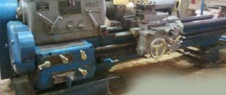
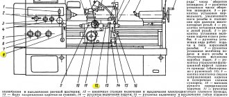
Basic methods for checking a lathe
When checking a lathe for accuracy, the main checks are the bed guides, spindle runout and lead screw.
The bed guides must be straight in the longitudinal direction. When worn, grooves, scratches, and sometimes nicks appear on them. Wear can be detected by superficial inspection and using measuring tools. To determine its value, install the test ruler 1 (Fig. 255) one by one on the guides 2, then determine the gap between their surfaces and the ruler in the light and measure with a feeler gauge.
The following wear of the frame is considered acceptable: with a center height of up to 300 mm - 0.02 mm over a length of 1000 mm; with center heights greater than 300 mm - 0.03 mm at the same length. For new or repaired machines, only a convexity of the bed, but not a concavity, is allowed by this amount.
The bed guides for the tailstock must be parallel to the carriage guides. Check the parallelism with an indicator mounted in the tool holder on the carriage (Fig. 256), which is moved along the frame; The indicator pin rests against the tailstock guide. The permissible deviation is up to 0.01 mm for machines with a center height of up to 200 mm and up to 0.02 mm for machines with a center height of more than 200 mm.
The horizontality of the frame guides is checked with a level, as shown in Fig. 257, moving ruler 2 with level 1 along the frame guides. The permissible deviation is 0.05 mm over a length of 1000 mm.
The spindle axis must be parallel to the bed guides in the vertical and horizontal planes. To check, insert a test mandrel into the conical hole of the spindle and check it with an indicator for the absence of runout along its entire length. Then the indicator is secured to the carriage and installed so that the indicator pin touches the mandrel, first in the vertical (Fig. 258, a) and then in the horizontal (Fig. 258, b) plane. With each installation, moving the carriage along the mandrel to a length of 300 mm, note the deviations of the indicator, which should not exceed 0.01 mm in the vertical plane for machines with a center height of up to 200 mm and 0.02 mm for machines with a center height of up to 400 mm. In the horizontal plane, indicator deviations should not be more than 0.01 mm for machines with any center height.
Deviation of the mandrel, counting to the right of the headstock, is allowed in the vertical plane only upward, and in the horizontal plane - only towards the cutter.
The spindle journals should rotate without wobbling. The spindle is checked for runout using an indicator mounted in the cutting head. When checking, it is necessary that the pin 1 of the indicator rests on the neck 2 of the spindle (Fig. 259, a). The permissible deviation is 0.01 mm for center heights of up to 350 mm and 0.02 mm for center heights of more than 350 mm.
The spindle must not have axial movement during rotation. The check is carried out as in the previous case, but the pin 1 of the indicator (Fig. 259, b) is pressed against the end of the collar 2 of the spindle. The permissible deviations are the same as when checking the journal runout.
The top of the front center should not have any runout when rotating. To check, the indicator is fixed in the cutting head (Fig. 259, c) and its pin 1 is pressed against the center cone 2. The permissible deviations are the same as in the previous two cases.
The pitch accuracy of the lead screw is checked using an accurate threaded mandrel 1, installed between the centers of the front and rear stock (Fig. 260), and an accurate cylindrical nut 2, screwed onto the threaded mandrel. The nut 2 has a longitudinal groove into which the ball of the holder 3, which carries the indicator 4 and is fixed in the machine support, is inserted. The tip of the indicator rests against the end of the nut, which is held from rotation by the ball of the holder. The machine is adjusted to the mandrel thread pitch. Having started the machine with the split nut turned on, monitor the indicator readings. Permissible deviations: 0.03 mm at a length of 100 mm and 0.05 mm at a length of 300 mm for machines with center heights up to 400 mm.
Practical testing of lathe accuracy. In addition to the geometric checks discussed, a comprehensive practical check of the accuracy of the lathe is carried out. The purpose of the test is to assess the accuracy of the machine in operation when manufacturing parts with cylindrical and end surfaces. During this check, the resulting deviations in ovality, taper and flatness are determined, which should not exceed the deviations established by GOST: ovality 0.01-0.02 mm and taper 0.02 mm over a length of 1000 mm and concavity of the end no more than 0 .02 mm on a diameter of 300 mm.
Tools for checking the accuracy of machine tools
The following tools are used to check the equipment:
- rulers;
- squares;
- set of mandrels;
- measuring heads;
- levels;
- probes;
- indicators.
- interferometer
Rulers are used to check the straightness and flatness of surfaces. Mandrels are used to determine the runout of rotating elements such as a spindle. The spindle bore is checked with a mandrel inserted into the spindle. The mandrel is rotated several times in half a circle, the runout is the difference between the maximum and minimum values.
Perpendicularity is checked using a square. An auxiliary tool is a feeler gauge, which is used to determine the presence and size of the gap between the plane and the square. It is also possible to use an indicator with a magnetic stand
The levels are intended to check the accuracy of installation of equipment on the foundation in two planes. Accurate measurements are made by verified levels with a micrometric scale.
Machine tools can also be checked with special-purpose instruments - theodolites, profilometers and profilographs, interferometers.
Checking machine elements for accuracy
The accuracy of the lathe is checked in accordance with GOST requirements: Some of the checks are given below:
- Radial runout of the spindle journal. The indicator measuring pin is placed so that it touches the surface of the neck and is perpendicular to the generatrix.
- Spindle bore radial runout. To do this, a cylindrical mandrel is tightly placed in the spindle. The spindle rotates and the indicator measures the runout. The amount of runout is measured at the spindle and at several points on the mandrel.
- Parallelism of the spindle axis relative to the longitudinal movement of the support. To check, a cylindrical mandrel is also fixed in the spindle. The indicator measuring pin must touch the top surface of the mandrel and be perpendicular to its generatrix. The support is moved along the frame guides by 300 mm. The measurements are repeated with the pin positioned horizontally so that it touches the side of the mandrel.
- Spindle axial runout. The measurement involves securing a short mandrel to the spindle. The indicator measuring pin is placed along the spindle axis so that its end touches the center of the mandrel end. The spindle rotates and the runout is measured.
- End runout of the spindle shoulder. The indicator measuring pin is placed so that it touches the end of the bead at the very edge. The spindle rotates and the results are recorded. To obtain accurate data, it is necessary to take measurements at at least two points. The final error is considered to be the maximum indicator reading.
- Parallelism of the quill movement relative to the longitudinal movement of the caliper. First, the test is carried out with the quill pushed into the tailstock and secured in it. The indicator is placed on the caliper, and its measuring pin touches the top surface of the quill. The caliper is moved and the data is measured. By analogy with the previous test, measurements are repeated with the pin touching the side of the quill. Then the same measurements are taken, only the quill is pulled halfway out of the tailstock.
- Parallelism of the quill hole relative to the longitudinal movement of the caliper. This check is carried out in the same way as for the spindle bore. A mandrel is fixed in the quill hole, and the measuring pin touches it from above. The support moves along the bed. The final error value is the arithmetic mean of three measurements.
- The height of the spindle and quill rotation axes coincides above the longitudinal guides of the bed. To measure at the centers, a cylindrical mandrel (rolling pin) is clamped, and the indicator is moved with a caliper, determining the maximum deviation.
- Parallel movement of the upper slide of the caliper relative to the spindle axis. A mandrel is fixed in the spindle, the indicator moves along the upper slide.
How to properly check a lathe
The quality of the test largely depends on how correctly the equipment is installed on the test bench. The machine must be installed strictly following the drawing. The most popular and reliable way is to install the unit on several supports (more than three). All moving components and elements must be installed in the middle position.
The quality of manufactured products depends on the geometric accuracy of the equipment. Therefore, the workpiece must be installed on a geometrically correct surface.
To determine the degree of wear, a ruler is installed in turn on each guide of the machine. Then, using a feeler gauge, you need to measure the gap between the ruler and the guide. GOST defines the maximum permissible value of this gap - no more than 0.02 mm. With a larger deviation, the processed parts may have an unacceptable output error.
Accuracy largely depends on the horizontality of the machine guides. This indicator is measured using a special level. The maximum deviation should be no more than 0.05 mm.
When checking the equipment for serviceability, pay attention to all rotating parts. Their movement must be carried out strictly along the axis; beating during rotation is unacceptable
If any element deviates from the axis of rotation, this not only affects the quality of the manufactured products, but also threatens the safety of the operator. When the workpiece “beats” in the machine, there is a risk of injury due to a part flying out of the holders or a broken tool.
When checking equipment, it is also important to determine the accuracy of the propeller pitch. To determine the error and deviation there is a special technique: Read also: DIY garage tables
Read also: DIY garage tables
a mandrel is installed in the headstock of the machine;
a cylindrical nut with a groove is fixed onto it;
a holder with an indicator is fixed into the groove of the nut, which should rest against the end of the nut;
the device must be configured for a threaded pitch;
During operation, the indicator records the error.
General points and features of drawing up the act
If you are tasked with inspecting equipment and drawing up a report on its technical condition, look at the recommendations below and familiarize yourself with a sample document.
Before moving on to the description of this particular act, we will provide some general information that is typical for all such papers. Today, standard forms of primary documents have been abolished, so company representatives can write them in any form - this also applies to the act on the technical condition of equipment. At the same time, if your organization has an approved template for such a document, it is better to follow it - this will save time and eliminate the need to rack your brains over its composition and text.
The act can be written on the company’s letterhead or on a blank sheet of any suitable format (usually A4), by hand or on a computer. When entering information, you must try to avoid inaccuracies, erasures and corrections - in the future they can play a negative role in establishing the legality of the document.
Another important requirement that must be taken into account is to have the form certified with the autographs of all members of the commission who were present when certifying the technical condition of the equipment. A stamp on the form needs to be placed only when the clause on its use for this type of paper is enshrined in the accounting policy of the organization
A stamp should be placed on the form only when the clause on its use for such papers is enshrined in the accounting policy of the organization.
The act is written in several copies - one for each member of the commission. Information about the act must be included in a special accounting journal.
After drawing up, the act should be placed in a separate folder along with other similar documents, and after the expiration of the storage period, it should be disposed of, following the algorithm established by law.
BASIC POINTS
1.1. The accuracy of metal-cutting machines is determined by three groups of indicators: indicators characterizing the accuracy of processing of sample products; indicators characterizing the geometric accuracy of machine tools; additional indicators.
1.2. Indicators characterizing the accuracy of processing of product samples include: accuracy of geometric shapes and location of processed surfaces of product samples; constancy of batch sizes of product samples; roughness of processed surfaces of product samples.
1.3. Indicators characterizing the geometric accuracy of the machine include: accuracy of bases for installing the workpiece and tool; accuracy of movement trajectories of the working parts of the machine, carrying the workpiece and tool; accuracy of the location of the axes of rotation and directions of linear movements of the working parts of the machine, carrying the workpiece and tool, relative to each other and relative to the bases; accuracy of interconnected relative linear and angular movements of the working parts of the machine, carrying the workpiece and tool; accuracy of dividing and installation movements of the working parts of the machine; accuracy of coordinate movements (positioning) of the working parts of the machine, carrying the workpiece and tool; the stability of some parameters with multiple repetitions of the test, for example, the accuracy of approach to a hard stop, the accuracy of small approach movements.
1.4. Additional indicators of machine accuracy include the ability to maintain the relative position of the working parts of the machine carrying the workpiece and the tool, subject to: application of an external load (stiffness indicators); exposure to heat generated when the machine is idling; machine vibrations that occur when the machine is idling. (Changed edition, Amendment No. 2).
1.5. The scope of testing machines for accuracy should be minimal, but sufficient to obtain the necessary reliability of test results and assess the accuracy of the machine.
1.6. When choosing the accuracy parameters to be tested, preference should be given to the most significant of them, taking into account the degree of reproducibility of measurement results, stability and accuracy of measurement.
1.7. The list of machine tool accuracy indicators is determined by the standards for accuracy standards of machine tools of specific types and technical conditions.
1.8. The accuracy standards of a machine after medium and major repairs must comply with the requirements of the standards and technical conditions in force during the period of manufacture of the machine.
1.9. Classification of machines by accuracy
1.9.1. Five accuracy classes of machine tools are established according to the absolute classification system, designated in increasing order of accuracy level: N, P, B, A and C. The division of machine tools into accuracy classes is carried out by type of machine, based on the requirements for processing accuracy. The same accuracy class should include machines that provide the same processing accuracy of sample product surfaces corresponding in shape and size. For certain types of machines intended only for grinding work, accuracy classes are not established. (Changed edition, Amendment No. 1, 3).
1.9.2. The tolerance values for accuracy indicators when moving from one accuracy class to another are preferably taken according to a geometric series with a denominator of 1.6. For specific indicators of geometric accuracy, it is allowed to take other values from 1.0 to 2.0. (Changed edition, Amendment No. 3).
1.9.3. Accuracy classes for individual types of machine tools should be established in the standards for accuracy standards for these types of machine tools, and in the absence of standards, in the technical specifications for the machines.
1.9.4. (Deleted, Amendment No. 3).
Plasma cutting of metal
We provide metal plasma cutting services.
FAQ.
1. Do you have the material?
The material is varied, steel, from ordinary carbon to alloyed, brass, copper, bronze, textolite, caprolon, ebonite, etc. By agreement, we will find unique grades of steels and alloys.
2. Do you take single orders?
We take orders from the 1st unit. Minimum order 2000 rub.
3. What are the prices and how much does it cost to make a part?
Prices range from 300-800 rubles/hour of machine time, depending on the order volume and complexity. A correct assessment can be given after studying the drawing, sketch or provided sample of the product sent by email. For urgency, the extra charge is from 20 to 50%, depending on the volume and degree of urgency.
4. What are the production times?
Production time is from 2 days depending on the volume of the order.
Classification of metal-cutting machines by accuracy
According to the classification of machine tools developed in the USSR, they are divided into five classes according to accuracy, shown in Table. 171.
Table 171
| Machine accuracy class | Accuracy class designation | The relationship between the basic tolerances of machine tool accuracy |
| Normal precision machine tools | N | 1 |
| High precision machines | P | 0,6 |
| High precision machines | IN | 0,4 |
| Particularly high precision machines | A | 0,25 |
| Ultra-precision machines | WITH | 0,15 |
As can be seen from table. 171 the ratio between tolerance values when moving from class to class for most accuracy indicators is assumed to be φ = 1.6.
This ratio makes it possible to harmonize the requirements for the accuracy of the machine with the requirements for the accuracy of the products processed on it, since the coefficient of 1.6 is taken into account in the tolerance systems of parameters that characterize the accuracy of the surfaces of widely used products. High-precision machines, as a rule, are manufactured on the basis of normal-precision machines, differing from them mainly in more precise manufacturing and selection of individual parts and improved installation quality.
High and especially high precision machines differ from previous ones in the special design features of individual elements, the high precision of their manufacture and special operating conditions.
Ultra-precision machines are designed for processing parts of the highest precision - indexing gears and disks, standard gears, measuring screws, etc.
When accepting machines of a higher accuracy class than those regulated by the standards given below, you can use the accepted ratio of the main accuracy indicators when moving from a lower to a higher class by multiplying the permissible deviations by 0.6.
Comparison of GOST accuracy standards and foreign standards
Comparing the USSR standards (GOST) for accuracy standards for metal-cutting machines with similar standards in other countries, it should be noted:
- In terms of the number and range of machines covered by standards for precision standards (about 65 existing GOSTs), the USSR occupies a leading position.
- The scope of precision testing of machine tools, regulated by GOST, basically corresponds to that adopted in most foreign standards. The difference mainly concerns inspections of individual parts (frames, lead screws, dividing disks), which are controlled during their manufacture and assembly and, as a rule, are not included in GOST.
- The values of permissible deviations of parameters given in GOST for accuracy standards also generally correspond to those adopted in most foreign standards. Increased industrial requirements for the quality of manufactured machine tools, in particular for their accuracy, reliability and durability, as well as the conditions for the supply of machine tools for export, pose the task of ensuring sufficient operating time of machine tools with a given accuracy for the machine tool industry of the Soviet Union. In particular, in the manufacture of machine tools for export, it is allowed to use only part of the tolerance range for the accuracy of the machine tools. It seems necessary in some cases, where appropriate, to impose more stringent requirements for accuracy and introduce verification of new parameters. In the near future, new and revised GOSTs will be released with higher requirements for a number of machine tool accuracy indicators and the addition of increased accuracy classes in accordance with the developed classification.
- It should be borne in mind that in some cases the tolerances specified in foreign standards are unjustifiably overstated and therefore, when comparing them with GOST accuracy standards, it is necessary to check the feasibility of this overestimation, as well as analyze the impact of reduced requirements for the accuracy of individual parameters on the accuracy of the machine in accordance with its purpose.
- The given tables comparing the accuracy standards of GOST and foreign standards (Tables 172-192) do not always provide completely identical checks, both in terms of the methodology for carrying them out and the control equipment used, and in terms of the lengths to which accuracy tolerances are assigned. In such cases, the tables provide the appropriate disclaimers. Tolerances are recalculated depending on the lengths to which they are assigned. It is also necessary to take into account that various standards have adopted their own system of interconnection of individual checks, and a literal comparison of their accuracy without taking this interrelation into account does not always make it possible to judge the actual accuracy of machine operation. In these cases, a more in-depth analysis of the compared accuracy indicators is required, as well as checking the accuracy of the machines under exactly the same conditions.
- When comparing permissible deviations according to GOST and foreign standards, it should be taken into account that in the manufacture of machine tools supplied by factories of the Soviet Union for export, it is allowed to use only part of the tolerance field for accuracy according to GOST: 0.6 - from the tolerance value - for machines of normal and increased accuracy; 0.8 - from the tolerance value - for high and especially high precision machines.
Features of the drilling process and checking the accuracy of drilling equipment
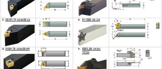
Features of the geometry of the cutting tool (in this case, a drill), as well as more complex working conditions, distinguish the cutting process during drilling from similar metal cutting processes, such as milling, turning or planing. A special feature here is the fact that the drill itself is not single-edged (compared to the cutter). This cutting tool is multi-bladed; its operation involves two main blades, two auxiliary blades (located on the guide strips of the drill itself) and a jumper blade.
Technological features of the drilling process require specific testing of the accuracy of the drilling machine. This procedure is regulated by GOST 370-93 and includes an accuracy study taking into account the following nuances:
- general requirements - according to GOST 8-82;
- geometric parameters - according to GOST 22267-76, measurement methods and schemes are regulated;
- set the movable organs in the middle position and secure them;
- study the radial runout of the surface of the centering hole;
- measure the radial runout of the spindle cone itself. The following types of runout are considered here: internal runout;
- external runout;
Attention should be paid to the fact that, by mutual agreement with the manufacturer, the consumer has the right to choose only those types of functioning tests (compliance with GOST runout and perpendicularity indicators) that interest him to a greater extent and correspond to his technological requirements. This point must be documented when placing an order for the manufacture of the machine.
A study of compliance with GOST accuracy standards is carried out for all newly produced machines at the manufacturing plant.
Types and principles of operation of drilling machines
The main objective for equipment modernization has always been multifunctionality. Modern metal drilling machines, when equipped with additional equipment and tools, can cope with more than just drilling and reaming holes. The range of operations they perform is quite wide. It consists of: countersinking, countersinking, reaming, threading (with a tap), boring holes (with a cutter), smoothing (with roller or ball mandrels).
When choosing different types of drilling machines, the main parameter is the size of the holes (maximum nominal diameter). Significant ones include technological indicators of spindle movement (its reach, maximum stroke) and machine operating speed.
All of them are divided into the following types according to the direction of drilling:
- horizontal drilling - used to produce holes of different depths (possibly five times or more in diameter) when drilling in a horizontal position;
- radial drilling - the principle of its operation is to align the axes of the spindle with the workpiece, while the spindle moves on a traverse in the radial direction in relation to the workpiece, which is fixedly mounted;
- vertical drilling - the operating principle here is the rotation of the spindle itself with the tool rigidly fixed in it (the feed itself is carried out in the vertical direction). The workpiece is located on the work table, and the rotation axes of the spindle and the workpiece are aligned by moving it.
General indicators that characterize the accuracy of machine tools are regulated by GOST 8-82. It is for this reason that GOST analyzes the following series of indicators:
- base (on which the working tool and workpiece are installed);
- the trajectory of movement of the working body, which delivers the workpiece to the cutting tool itself;
- the location of the rotation axes and the direction of movement of the working bodies, which directly feed the workpiece and tool;
- installation and motor movements of working bodies;
- coordinate movements (another term is positioning) of these bodies that feed the workpiece to the cutting tool (drill).
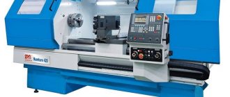
Diagnostics of CNC machines
Modern methods of diagnosing CNC machines are a set of works aimed at examining the target equipment and identifying a malfunction - failure or malfunction. Diagnostics is carried out in two stages:
- Checking the condition of the machine makes it possible to identify structural causes of failure - as a rule, we are talking about the breakdown of some component or part. Partial or complete disassembly of the unit may be required.
- Checking a numerical control system involves diagnosing the machine by testing the control program. Test results and errors are displayed using special codes.
The first stage of checking machines requires the use of specific tools - levels, indicators, gauges, protractors, micromeasures. At the control program verification stage, the engineer uses backplot or solid-state verification, simulating the operation of the machine, and then conducts a final check on the equipment.
Checking machines for accuracy:
The specifics of equipment diagnostics are determined, among other things, by the purpose, for example, checking a lathe for accuracy is a strictly regulated set of diagnostic procedures aimed at confirming the correspondence of the data in the passport with real data. In this case, it is necessary to check the following parameters:
- Movement of elements holding the workpiece.
- The arrangement of the surfaces on which the workpiece and tool are based.
- Matching the shape of the base surfaces.
Also, checking a machine for geometric accuracy includes assessing the trajectory of movements, angular and linear movements of machine parts, and it is possible to evaluate other parameters. All accuracy requirements are specified in the equipment passport, and errors are identified based on the relevant GOST standards, for example, GOST 8-82 and GOST 18097-93.
Please note that checking machines for technological accuracy is dictated by the natural wear and tear of the equipment during operation. We are not talking about wear of cutters, drills or cutters
Permanent components of the machine are diagnosed, for example:
- drives;
- calipers;
- consoles;
- spindles.
Checking a machine for accuracy, provided it has a CNC, also involves diagnosing measuring devices that are necessary for implementing the control program and automatically processing workpieces. As a result of the check, the possibility of further use of the diagnosed machine in this area is determined. In case of a critical error, equipment is repaired, modernized or replaced.
Machine diagnostics regulations:
The schedule for routine diagnostics of machine tools is drawn up based on the list of machine equipment. This document includes information about the operating mode of the machine and all operations that affect its accuracy.
Diagnostics of CNC machines can be carried out not only in a planned manner, but also in emergency mode - this scenario is determined by the relevant regulations developed specifically for force majeure circumstances.
Please note that since all inspections are carried out under conditions of temporary equipment decommissioning, drawing up an inspection schedule is a complex and important undertaking that takes into account all aspects of the production activities of the workshop and the enterprise as a whole. As a rule, this schedule is drawn up by the chief technologist of the plant
Diagnostics of different types of machines and individual components:
Obviously, milling machine inspection and lathe inspection are two separate sets of procedures, the differences between which are due to differences in equipment design. Also, in some cases, it is not the entire machine that requires inspection, but a specific unit.
For example, checking the tailstock of a lathe evaluates the reliability of fixation in the selected position and the accuracy of movement in the direction of the spindle while maintaining alignment during rotation. Ensuring the reliability of fastening and stability determines the class of processing accuracy.
Today, our specialists have enough experience and are properly qualified to implement modern diagnostic methods for CNC machines of all types. We perform scheduled and emergency checks, evaluate the performance and accuracy of individual components, and diagnose control programs. We provide a guarantee for all types of work performed, and provide free consultations on any issues.
Checking machines for technological accuracy
Metalworking accuracy is the basic criterion for assessing the quality of metal products. The priority task is to minimize deviations in the dimensions of manufactured products from the specified parameters. To solve this problem, periodic monitoring of machines is carried out for technological accuracy. It should be understood that such a check is more than just inspecting and measuring the relevant parts of the equipment. In the course of this work, a whole range of activities is carried out.
Prevention
Diagnostics are carried out not only to detect the causes of failure, but also to perform preventive maintenance of the CNC device. Exactly what actions should be carried out with preventive maintenance, and how often they should be carried out, are indicated in the instructions for the device. The purpose of machine tool prevention and maintenance is to maintain the operating condition of machine parts, care for them, and solve problems at an early stage.
During prevention:
- the moving components of the photo-reading device are lubricated;
- cooling fans are lubricated;
- the equipment structure is cleaned of dust and dirt;
- air filters of the ventilation system are cleaned or replaced with new ones;
- Contacts and electronic components are cleaned.
If malfunctions occur after preventive actions, the participation of specialists is required.