Among the various metal processing techniques, milling has gained the most popularity. Milling can be used to work with workpieces made of materials of any strength and involves cutting layers of metal using a rotating cutter. Metal milling can be performed both on conventional machines and on equipment equipped with CNC, which allows producing products with minimal dimensional errors in a short time.
Benefits of technology
The key advantage of this technique is its versatility, since using different cutters and cutting technologies on one milling machine you can perform many procedures and work with metal, plastic, wood, caprolon, etc.
Depending on the shape of the workpiece, the cutting equipment used and the milling method, the machines allow you to perform the following types of manipulations:
- engraving and applying patterns of any complexity;
- cutting metal parts into several elements;
- grinding surfaces using special attachments with abrasive;
- drilling holes and grooves;
- carving;
- formation of modular surfaces, etc.
Metal milling stages
The quality of metal products or other materials produced during the milling process depends not only on the workpiece, but also on compliance with the technology, which includes certain stages:
- Preparation for work, during which the cutting tool is installed on the spindle and the workpiece is fixed on the work table of the machine tool.
- Setting operating parameters - the depth of material cutting in one pass, the rotation speed of the cutting equipment, the direction of movement of the workpiece and the degree of smoothness of its feeding.
- Starting the rotation of the cutting part at low speed to slightly touch the cutter with the material being processed. This allows you to check the correct depth of cut and the safety of the process, after which the spindle is retracted to its original position and, if necessary, the performance characteristics are adjusted.
- Restarting the electric motor, starting the feed of the workpiece and carrying out the milling process with constant monitoring of the criteria of the part being formed.
Contour milling with end mills
There are two main technologies for contour milling with end mills.
With a combination of manual feeds
The technology looks like this.
- The workpiece is fixed on a table or in a vice.
- The part is processed with an end mill along the marked contour (the table moves in the longitudinal and transverse directions).
Note! It is impossible to mill a contour in one go. The part is first rough-processed and then finished.
Image No. 21: milling a curved contour with a combination of manual feeds
Using a round turntable
When milling workpieces on round rotary tables, the contours of the arcs are formed due to their circular feeds. Devices can be manual or mechanical. Using this technology, high-precision contours are obtained.
Image #22: Round rotary table with manual feed
Note! Above we examined only the main areas of application of end mills. Read about other operations and the peculiarities of their implementation in specialized literature.
Processing type
Depending on the nature of the processing carried out during the manufacturing process of parts, the technological process is divided into several steps:
- Material roughing is the initial removal of bulk chips to form the overall profile of the part. This finishing stage has a low accuracy class with allowances depending on the material of 3–7 mm.
- Semi-finishing is the subsequent type of cleaning with the removal of fine chips and the accuracy of the work performed from class 4 to class 6.
- Finishing – detailed high-precision finishing of class 6 or 8. In this case, the maximum allowance is from 0.5 to 1 mm, which ensures high quality of the formed surface.
Contact us
Rosta LLC offers metal band sawing machines at prices 1.5 - 2 times lower than analogues from foreign manufacturers,
with the same quality and reliability. Automatic, semi-automatic and manual options are available. Our machines will allow you to solve even the most complex problems of any enterprise. To leave a request or clarify the information you are interested in, call: (473) 239-65-79;, and the managers of Rosta LLC will provide all the information you are interested in.
Advantages of using CNC machines
Working on a conventional milling machine requires increased care and precision, on which not only the safety of the operator, but also the result of the work performed will depend. That is why all actions must be performed according to the instructions, and operating parameters must be set based on the table located on the equipment. But, even in this case, the quality of the manufactured part may not meet the requirements, since when working on classic milling machines, there is always the possibility of human factor influence.
That is why numerically controlled milling machines are becoming increasingly popular, which make it possible to produce high-quality parts with minimal dimensional errors. The technology of working on CNC machines is similar to the process carried out on conventional equipment. But, in this case, the cutting depth, configuration and dimensions are set in a program that automatically performs all the work.
The active replacement of conventional machines with CNC equipment is due to the fact that to create a product, the operator only needs to check all the moving mechanisms, change the cutting equipment, secure the workpiece on the milling table, set up the program and start the engine. Next, he only needs to observe the work process and remove the manufactured part from the table. In addition to ease of operation for humans, CNC machines have other advantages:
- high speed of production of parts, which exceeds the production process carried out on units without program control;
- a significant reduction in the time for changing cutting equipment by equipping the equipment with a turret working head, which, depending on the model, can fix up to 12 cutters;
- accuracy of material processing with an error of no more than 0.01 mm;
- cleanliness of processing, since the movement of the equipment and the feeding of the workpiece is very smooth, which ultimately makes it possible to obtain products with a surface that looks polished;
- the ability to manufacture parts with configurations of any complexity;
- ease of maintenance, allowing one operator to simultaneously work on 2–4 machines at once, depending on the complexity of the part and the duration of its processing.
Milling closed slots with end mills
The task is to mill a closed groove in the plank. Length - 32 mm. Width - 16 mm.
Image No. 13: plank drawing
Tool selection
The same cutter with five teeth (z = 5) will do.
Cutting mode calculation
The specified cutter feed is 0.01 mm/tooth. Cutting speed - 25 m/min. Frequency - 500 rpm. Let's calculate the minute feed.
s = stooth*z*n = 0.01*5*500 = 25 mm/min.
The minimum feed on the machine is 31.5 mm/min. We install it exactly. Let's calculate the actual feed per tooth.
stooth = s/(z*n) = 31.5/(5*500) = 0.013 mm/tooth.
Performing an operation
When milling through grooves:
- first, a manual vertical feed is given so that the cutter cuts into the material 4–5 mm;
- after this, the mechanical longitudinal feed is turned on and a blind groove of the required length is cut out;
- Gradually raise the table until a through hole is obtained.
Image No. 14: securing the workpiece and milling the through groove
Metal milling technology: up and down milling
To process materials, milling methods are used that differ in the direction of supply of the material used. As a rule, when roughing primary finishing of metal or hard alloy workpieces, counter milling is most often used. With soft metals and during semi-finishing or finishing processing, it is better to work using the passing method. In addition to the application features, these methods of work have their own advantages and disadvantages that determine their relevance.
Associated technology
In the process of using down milling, the cutting equipment rotates in the same direction in which the workpiece arrives, which determines a number of advantages of this method:
- under the influence of inertial forces, the workpiece is firmly held on the frame, so there is no need for its strong fixation to the table, which reduces the likelihood of material deformation;
- the allowance is removed with maximum smoothness, due to which only slight roughness is formed on the surface;
- the cutting edge of the cutter has slight wear, since during parallel movement they become dull at a lower speed;
- quick removal of chips without the use of additional tools or devices.
But, in addition to its advantages, this technology also has a number of disadvantages. Climb milling is not suitable for working with metals with many solid inclusions; it requires preliminary preparation of rough surfaces and is accompanied by strong vibrations, which can only be eliminated by using a machine with high rigidity.
Up milling
Unlike down milling, up milling involves directing the cutting tool to meet the movement of the workpiece. Thanks to this, it is possible not only to increase productivity, but also to obtain other advantages:
- minimal load on the mechanism, thereby extending its working life;
- a soft and uniform effect on the metal during the cutting process, allowing you to gradually increase the depth of cut without deviating from the permissible dimensions;
- absence of vibrations, even when processing metal with a rough, rough surface.
The disadvantages of counter milling include the fact that the workpiece needs to be securely fixed, since the cutting force is partially aimed at tearing the template away from the bed. In addition, the disadvantage is the rapid wear of the cutter and the fact that chips are poorly discharged and can fall into the cutting zone.
Cutting speed
The most important mode during milling can be called cutting speed. It determines over what period of time a certain layer of material will be removed from the surface. Most machines have a constant cutting speed. When choosing a suitable indicator, the type of workpiece material is taken into account:
- When working with stainless steel, the cutting speed is 45-95 m/min. Due to the addition of various chemical elements to the composition, hardness and other indicators change, and the degree of workability decreases.
- Bronze is considered a softer composition, so this mode when milling can be selected in the range from 90-150 m/min. It is used in the manufacture of a wide variety of products.
- Brass has become quite widespread. It is used in the manufacture of locking elements and various valves. The softness of the alloy allows you to increase the cutting speed to 130-320 m/min. Brasses tend to increase in ductility when exposed to high heat.
- Aluminum alloys are very common today. In this case, there are several design options that have different performance characteristics. That is why the milling mode varies from 200 to 420 m/min. It is worth considering that aluminum is an alloy with a low melting point. That is why, at high processing speeds, there is a possibility of a significant increase in the plasticity index.
There are quite a large number of tables that are used to determine the main operating modes. The formula for determining cutting speed revolutions is as follows: n=1000 V/D, which takes into account the recommended cutting speed and the diameter of the cutter used. A similar formula allows you to determine the number of revolutions for all types of processed materials.
The milling mode in question is measured in meters per minute cutting parts. It is worth considering that experts do not recommend driving the spindle at maximum speed, as wear increases significantly and there is a possibility of damage to the tool. Therefore, the result obtained is reduced by approximately 10-15%. Taking this parameter into account, the most suitable tool is selected.
The rotation speed of the tool determines the following:
- The quality of the resulting surface. For the final technological operation, the largest parameter is selected. Due to axial rotation with a large number of revolutions, the chips are too small. For roughing operations, on the contrary, low values are selected, the cutter rotates at a lower speed, and the chip size increases. Due to fast rotation, a low surface roughness is achieved. Modern installations and equipment make it possible to obtain a mirror-type surface.
- Labor productivity. When setting up production, attention is also paid to the productivity of the equipment used. An example is the workshop of a machine-building plant, where mass production is being established. A significant decrease in processing modes causes a decrease in productivity. The most optimal indicator significantly increases labor efficiency.
- The degree of wear of the installed tool. Do not forget that when the cutting edge rubs against the surface being processed, severe wear occurs. With severe wear, the accuracy of the product changes and labor efficiency decreases. As a rule, wear is associated with strong surface heating. That is why high-throughput production lines use equipment that can supply coolant to the material removal zone.
In this case, this parameter is selected taking into account other indicators, for example, feed depth. Therefore, the technological map is drawn up with the simultaneous selection of all parameters.
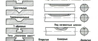
Types of cutters for processing
Milling work is classified according to the type of cutting equipment used, which distinguishes the following methods and main types of milling:
- An end cutter, which is produced using an end mill, similar to a drill of short length and increased diameter, on the end of which 5 or more cutters are fixed along the entire circumference with different pitches and the same planting depth. Such equipment is used to form grooves, undercuts, windows, wells, as well as reverse milling, cutting ends, and forming more accurate dimensions of the workpiece.
- Cylindrical, necessary for adjusting the height of long and short edges, for example, the height of the channel ribs. In this case, the work is carried out with a universal-purpose screw cutter in the form of a horizontal roller, or with equipment with straight teeth for working on straight surfaces.
- Disc, carried out to form ordinary longitudinal grooves using a cutter resembling the cutting part of a circular saw.
- Angular, performed by a tool in the form of two truncated cones connected together, the angle of which corresponds to the angle of inclination of the groove on the product. The equipment can be made entirely of high-speed steel, or supplemented with insert cutters made of pobedit alloy for cutting metal of increased hardness.
- End, designed to create ledges of a certain size in both horizontal and vertical planes.
- Shaped, without which it is impossible to create products of non-standard shape. To do this, use pointed cutters with a complex profile and a sharp edge on the inside, or equipment with backed teeth.
In addition, there are other types: core cutters for producing large holes, hob cutters for processing material with several cutting edges at once, etc.
Vertical and horizontal milling
For milling, different equipment is used, which, depending on the nature of the manipulations, is divided into two types: vertical and horizontal. Each of them has its own application features, advantages and disadvantages.
Vertical milling
To perform this type of milling work, specialized vertical milling machines are used, the capabilities of which allow you to work in the horizontal and vertical planes, and carry out:
- drilling;
- making holes;
- countersinking.
They are used for processing not only metal, but also other materials, both in individual and continuous production. This equipment easily works even with cast iron and steel, allowing the production of high-quality spiral products, frames, gears, dies and more. Depending on the design, they can be manually controlled, CNC or fully automated.
The equipment received its name due to the vertically located spindle. Here the main movement is carried out by the cutter, and the workpiece is rotated only in accordance with the intensity of its processing or as needed. In this case, the movement of the workpiece directly on the milling table can be not only rectilinear, but also curved. The spindle head has the possibility of installation movement along special vertically located guides and moves together with the sleeve in the axial direction.
Depending on the design features, vertical milling machines are divided into two categories:
- Console - large-sized units with a massive console that allows drilling and work using end, cylindrical, face and shaped cutters. Due to restrictions on the position of free space, they are used to produce parts with low weight and workpieces of small size.
- Non-cantilever - in them the table moves along the guides of the main frame, fixed on the foundation, which allows for high rigidity, and therefore accuracy in processing products. Due to the absence of a console, this equipment can equip large workpieces and produce large-sized parts. Non-cantilever type machines are indispensable for processing not only vertical, but also inclined surfaces.
Horizontal milling
Milling work in the horizontal plane is carried out on special horizontal milling machines, in which the spindle is located horizontally. Such equipment can work with angle, disk and cylinder cutters, as well as prefabricated equipment with replaceable cutters. In addition to standard horizontal machines, there are universal ones with the ability to install tools of any type, designed not only for surface linear processing of metal, but also for complex cutting of recesses and grooves on rotating workpieces. Cutting is done at right angles and is best suited for forming grooves with rapid chip evacuation.
Milling inclined planes with angular end mills
Performed on horizontal milling machines. Processing of workpieces with corner cutters occurs at lower feed and cutting speeds. This is due to difficult working conditions.
For example, with a milling depth of 12 mm, a cutting speed of 11.8 m/min is prescribed. Spindle rotation frequency - 50 rpm.
Image #17: Milling an inclined plane with a miter end mill
Note! To avoid defects when milling an inclined plane:
- Before the operation, make sure the markings are accurate;
- secure the workpiece as securely as possible;
- thoroughly clean the vice and table from shavings;
- Check the angle of the tool or universal vice.
Technical problems of milling and ways to solve them
Despite the use of technologically advanced milling machines, this process may be accompanied by the emergence of a number of problems that have different reasons for their occurrence and solutions. One of the possible problems is injury to the operator from flying metal shavings, which is easily solved by organizing a system for its removal. But there are more significant problems for the milling process. These include an active reduction in the working life of the equipment and damage to the surface of the workpiece during processing.
Reduced tool life
This category of important technical and technological problems of milling includes:
- Rapid wear of the edge of the cutting equipment. As a rule, it occurs as a result of incorrect feeding of the material being processed, installation of inappropriate equipment or its rotation speed.
- Severe chipping of the edge of the cutter, caused by the wrong choice, installation of the spindle at a different angle, or too high a rotation speed. Also, the reasons for the formation of this problem can be caused by excessive pressure from the cutter or the poor condition of the surface being processed, which has not undergone the necessary preparation.
- Complete failure, which most often results from the use of a tool with insufficient strength and thermal shock. This problem can be avoided by using the right equipment and air or liquid cooling to regulate temperature and lubricate the work area. More rare causes of cutter failure include the absence or poor removal of chips, which leads to secondary cutting and transfer of an impressive load to the tool.
- The formation of build-up on the cutting edge and the adhesion of metal chips, which occurs when cutting soft metals (for example, aluminum) and using a cutter with an incorrectly selected angle. Solved by changing equipment.
Damage to the treated surface
The most common damage to workpiece material includes:
- The formation of hardening as a result of an increase in temperature in the cutting area with an increase in strength and a decrease in ductility. The situation can be avoided by using timely cooling of the part.
- Deviation from verticality, which usually occurs when the edge of the cutting equipment is heavily worn or when the cutting mode is incorrectly selected.
- Non-compliance with dimensions resulting from poor fixation, insufficient rigidity of the tool, unacceptable level of vibration or an increase in the replacement interval. The problem is corrected by changing the cutter, using a more rigid workpiece clamping force, and using vibration dampers.
- Chipping and the formation of unevenness, which are the result of incorrect setting of speed and depth, as well as lack of uniformity of feed of the workpiece.
A preliminary study of possible accompanying negative phenomena, their causes and solutions, will allow you to choose the right equipment and operating mode, which will generally affect the quality and productivity of the work process.