home
About company
Directory
I-beam
I-beam assortment
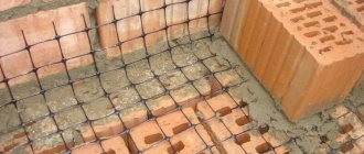
I-beams (I-beams) are a standard profile made of carbon and low-alloy steels, the cross-sectional configuration of which is close in shape to the letter “H”. The wide range of applications of I-beams is explained by their mechanical characteristics: an I-beam is several times stronger than a channel, approximately thirty times stiffer and almost seven times stronger than beams of square profiles with the same cross-sectional area.
I-beams are distinguished by the angle of inclination of the shelves (parallel and with a slope), by purpose and method of production: hot-rolled and welded.
Metal beams
Any metal I-beams are manufactured in strict accordance with the requirements of GOST and TU, so they have a regulated shape and composition. Thanks to this, having the necessary documentation, you can easily calculate the required dimensions and parameters of I-beams required for a specific design.
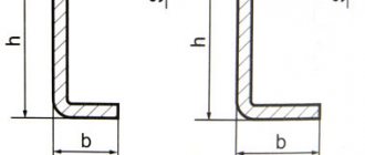
Geometric characteristics are:
- Height is the distance between two flat areas, called flanges, in the section of an I-section.
- Width is the length of the I-beam shelves.
- Wall thickness is the thickness of the middle plane located between the shelves. This parameter is one of the most important, since the load-bearing capacity and strength of the I-beam directly depends on the wall thickness.
- Average shelf thickness. The I-beam shelves are not rectangular, but have an irregular shape. Towards the ends of the shelf they narrow, and in the middle of the shelf, where it abuts the wall, they expand inward. Therefore, the average thickness of the shelf is calculated using the following formula: shelf width minus wall thickness divided by four.
- The radius of internal rounding is the parameter for rounding the shelf at its junction with the wall. Due to the fact that the shelf does not adjoin the wall at a right angle, but along a radius, its strength characteristics increase. The radius of curvature of the shelf. Since such thickness is not required at the ends of the flange and the main load goes to the center of the beam on the wall, the flanges of the I-beam taper along the radius.
- Slope of the inside of the shelf. The shelf can also run at a certain angle along the inside, widening towards the center.
The technical characteristics of the I-beam directly depend on these parameters, so all of them are specified in GOST and must be performed in strict accordance with them.
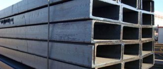
Corrugated beams: great savings
Although the corrugated beam looks interesting, in Russia such a design began to be used back in the 30s of the last century. Then something similar was used in wooden structures. Today, such beams are welded in several metallurgical plants in the country.
Now this type of beam is a welded lightweight structure made of corrugated sheets, which is welded to steel shelves. Moreover, the shelves themselves are made of hot rolled steel, and the profiled sheet is cold rolled.
Look what these beams look like:
The idea of corrugating the walls of such beams was arrived at in order to save money, or, to put it in literate language, to reduce the metal consumption of construction. Naturally, the corrugated wall can be thinner than a regular metal one (only 1.5-1.8 mm), because it already has transverse ribs.
Which, in addition, also increases the torsional rigidity of the beam itself! And, therefore, it allows you to get rid of the main drawback that is characteristic of the I-beam. Here the stress develops only at the belts, drops almost to zero, and all tangential stresses are evenly distributed along the height of the walls.
The corrugation itself can be either wavy or triangular (this is considered more technologically advanced). An even stronger beam does not have vertical corrugations, but horizontal ones.
In total, the corrugations are located to the upper belt at an angle of 45-50°, with the calculation of the ratio of the wave height to its length from 1/5 to 1/20.
Compared to conventional hot-rolled I-beams, corrugated beams are 20-40% more economical. Not only do such beams weigh less, but the profiling itself gives greater rigidity during rotation, and therefore fewer special lifting devices are used in the installation of such beams in the form of additional angles and ties. This greatly simplifies installation.
Corrugated beams are good as roofing purlins with a span of 9 m and as a load-bearing base in high-rise buildings with spans up to 24 meters.
The only significant drawback of such structures is that they are quite labor-intensive to manufacture. But, due to the fact that such beams do not have stiffeners, metal consumption and the length of welds are reduced.
What to consider when calculating an I-beam
To minimize waste and simplify the design, it is necessary to correctly perform the calculation. Such calculations can be performed independently, or they can be ordered from a design office.
The calculation is performed based on the following data:
- the length of the span in which the beam is planned to be used;
- load size - standard and design;
- calculated resistance, by default it is taken equal to 210 MPa;
- it is necessary to calculate the moment of axial resistance.
Having received the calculation results, you can select the required type of profile using the I-beam assortment table.
But, the designer must also take into account the fact that I-beams work very poorly in torsion, in comparison with a round beam.
Average prices in the Russian Federation
The cost of all I-beam products as of March 2022 is, on average, in the Russian Federation:
- Steel:
- for 1 ton – 51,700 rubles;
- for 1 m – from 845 to 16,350 rubles.
- Wooden:
- 1 m – from 220, 300, 430 to 900 rubles.
- JB:
- 1 PC. - from 850 to 4,500 rubles, up to 22,340 - crane, the largest.
The total cost is affected by the size and number of I-beams. The country (manufacturer) and region of the Russian Federation also matter. The most expensive prices for I-beams are in the Moscow Region, St. Petersburg and the northern regions .
Price lists with prices are available on the websites of official manufacturers of I-beams.
Production of welded I-beam
Welded products are made from sheet metal. The quality of the finished beam depends on the welding equipment used for its production. During production, the following operations are carried out:
- Cutting steel sheets on CNC machines (less commonly, thermal cutting equipment is used for this).
- Welding of workpieces on automated lines using hydraulic clamps.
- Editing the product to achieve the prescribed geometry.
IMPORTANT: I-beams made using outdated equipment from low-carbon steel grades lead to the fact that such building elements have low performance characteristics. Welded beams produced on modern equipment are not inferior in their properties to hot-rolled analogues. With the correct technology for their manufacture, they will help to achieve the necessary conditions for the construction of all types of buildings and structures.
The use of welding in the production of such metal products makes it possible to produce beams with different widths and thicknesses of shelves. The customer can receive a welded I-beam of a certain length, with holes and cutouts ready for fastening the structure.
I-beam channels have universal characteristics:
- Optimal shape for material consumption.
- High strength indicators.
- The parameters are specified in standards and specifications.
The disadvantages of hot-rolled metal structures of this kind are:
- Low resistance to torsion (this indicator is 400 times lower compared to a round beam).
- The difficulty of producing large sizes and their shortage on the market.
- High metal consumption of production.
Most sizes of hot rolled I-beams are available on the same day of purchase. Welded elements are most often produced to order. Therefore, you have to wait until the manufacturer finishes working on your beams.
In what structural elements is it used?
Such metal products are opening up new areas of use every day. Demand for them will encourage manufacturers to improve the process of creating beams. Today they are used not only in multi-storey buildings, but also in private construction.
I-beam structures tolerate bending resistance well. It is advisable to include them in the design of load-bearing elements:
- Column.
- Overlapping elements.
- Suspended tracks.
- Structures of frames of cars, cars and special equipment.
- Frames of mines and tunnels.
In the designs of moderately loaded trusses, a wide-flange I-beam is used. In order to reduce the cost of construction without reducing the strength of the structure, accurate calculation and selection of beams is necessary. This procedure must be entrusted to specialized architectural or design firms. Specialists of these bureaus will carry out calculations according to:
- Standard load (the corresponding GOST is used).
- The number of elements used in one beam.
- Average resistance value (according to steel grade).
When using floors made from beams of this profile, reinforced concrete, metal or brick columns and walls serve as support. Installation of formwork and construction of supports is carried out using measuring equipment. I-beams are mounted on supports so that they extend onto the support by at least 20 cm.
If it is necessary to join elements, the requirement of SP 16.13330.2011 is used. It prescribes three methods for this procedure:
- Butt welding of pre-milled ends.
- Bolted or welded linings.
- Flanges and bolts.
The I-beam is connected to the column with bolts. Installation is carried out using temporary connections, which are then replaced by the main ones. After installing such a beam, it must be protected from corrosion. For this purpose, special paint and varnish compositions are used. Until the main fastening is installed, the beam cannot be used. Designs using such elements are highly reliable and durable.
| Normal I-beams (without slope of the internal edges of the shelves | |||||
| Profile dimensions | Sectional area, F, sq.cm | Weight 1m, kg/m | |||
| b | s | t | R | ||
| mm | |||||
| 100 | 5,5 | 8 | 11 | 27,16 | 21,3 |
| 124 | 5 | 8 | 12 | 32,68 | 25,7 |
| 125 | 6 | 9 | 12 | 37,66 | 29,6 |
| 149 | 5,5 | 8 | 13 | 40,8 | 32 |
| 150 | 6,5 | 9 | 13 | 46,78 | 36,7 |
| 174 | 6 | 9 | 14 | 52,68 | 41,4 |
| 175 | 7 | 11 | 14 | 63,14 | 49,6 |
| 199 | 7 | 11 | 16 | 72,16 | 56,6 |
| 200 | 8 | 13 | 16 | 84,12 | 66 |
| 199 | 8 | 12 | 18 | 84,3 | 66,2 |
| 200 | 9 | 14 | 18 | 96,76 | 76 |
| 199 | 8,8 | 12 | 20 | 92,38 | 72,5 |
| 199 | 9 | 14 | 20 | 101,27 | 79,5 |
| 200 | 10 | 16 | 20 | 114,23 | 89,7 |
| 220 | 9,5 | 13,5 | 24 | 113,36 | 89 |
| 220 | 10 | 15,5 | 24 | 124,75 | 97,9 |
| 199 | 10 | 15 | 22 | 120,45 | 94,6 |
| 200 | 11 | 17 | 22 | 134,41 | 105,5 |
| wide-flange I-beams | |||||
| 150 | 6 | 9 | 13 | 39,01 | 30,6 |
| 175 | 7 | 11 | 16 | 56,24 | 44,1 |
| 200 | 8 | 12 | 18 | 72,38 | 56,8 |
| 201 | 9 | 15 | 18 | 87,38 | 68,6 |
| 249 | 8 | 11 | 20 | 83,17 | 65,3 |
| 250 | 9 | 14 | 20 | 101,51 | 79,7 |
| 299 | 9,5 | 12,5 | 22 | 112,91 | 88,6 |
| 300 | 10 | 16 | 22 | 135,95 | 106,7 |
| 300 | 11 | 18 | 24 | 157,38 | 123,5 |
| 300 | 11 | 15 | 26 | 145,52 | 114,2 |
| 300 | 14,5 | 17,5 | 26 | 176,34 | 138,4 |
| 300 | 15,5 | 20,5 | 26 | 198,86 | 156,1 |
| 300 | 16,5 | 23,5 | 26 | 221,38 | 173,8 |
| column I-beams | |||||||
| Profile designation | Profile dimensions | Sectional area, F, sq.cm | Weight 1m, kg/m | ||||
| h | b | s | t | R | |||
| mm | |||||||
| 20K1 | 196 | 199 | 6,5 | 10 | 13 | 52,69 | 41,4 |
| 20K2 | 200 | 200 | 8 | 12 | 12 | 63,53 | 49,9 |
| 25K1 | 246 | 249 | 8 | 12 | 16 | 79,72 | 62,6 |
| 25K2 | 250 | 250 | 9 | 14 | 16 | 92,18 | 72,4 |
| 25K3 | 253 | 251 | 10 | 15,5 | 16 | 102,21 | 80,2 |
| 30K1 | 298 | 299 | 9 | 14 | 18 | 110,8 | 87 |
| 30K2 | 300 | 300 | 10 | 15 | 18 | 119,78 | 94 |
| 30K3 | 300 | 305 | 15 | 15 | 18 | 134,78 | 105,8 |
| 30K4 | 304 | 301 | 11 | 17 | 18 | 134,82 | 105,8 |
| 35K1 | 342 | 348 | 10 | 15 | 20 | 139,03 | 109,1 |
| 35K2 | 350 | 350 | 12 | 19 | 20 | 173,87 | 136,5 |
| 40K1 | 394 | 398 | 11 | 18 | 22 | 186,81 | 146,6 |
| 40K2 | 400 | 400 | 13 | 21 | 22 | 218,69 | 171,7 |
| 40K3 | 406 | 403 | 16 | 24 | 22 | 254,87 | 200,1 |
| 40K4 | 414 | 405 | 18 | 28 | 22 | 295,39 | 231,9 |
| 40K5 | 429 | 400 | 23 | 35,5 | 22 | 370,49 | 290,8 |
| I-BEES WITH SLOPE OF THE INNER EDGES OF THE SHELVES | |||||||
| Profile designation | Profile dimensions | Sectional area, F, sq.cm | Weight 1m, kg/m | ||||
| h | b | s | t | R | |||
| mm | |||||||
| GOST 19425-74 | |||||||
| 24M | 240 | 110 | 8,2 | 14 | 10,5 | 48,7 | 38,3 |
| 30M | 300 | 130 | 9 | 15 | 12 | 64 | 50,2 |
| 36M | 360 | 130 | 9,5 | 16 | 14 | 73,8 | 57,9 |
| 45M | 450 | 150 | 10,5 | 18 | 16 | 98,8 | 77,6 |
| GOST 8239-89 | |||||||
| 60 | 600 | 190 | 12 | 17,8 | 20 | 138 | 108 |
I-beam: size table, weight and dimensional characteristics of profiles
Modern production allows us to produce profiles of various sizes, from a large number of materials and in a variety of configurations. It is possible to produce I-beams according to individual parameters.
This article contains a description of the most common I-beams in construction. For clarity of the information presented and the possibility of visual comparison, a table of sizes of I-beams is offered:
| Profile view | Width mm | Height mm | Shelf thickness, mm | Wall thickness, mm | Number of meters in 1 ton | Weight of 1 m length, kg |
| 10 | 55 | 100 | 7,2 | 4,5 | 105,7 | 9,456 |
| 12 | 64 | 120 | 7,3 | 4,8 | 86,62 | 11,54 |
| 14 | 73 | 140 | 7,5 | 4,9 | 73,09 | 13,68 |
| 16 | 81 | 160 | 7,8 | 5 | 62,94 | 15,89 |
| 18 | 90 | 180 | 8,1 | 5,1 | 54,50 | 18,35 |
| 18a | 100 | 180 | 8,3 | 5,1 | 50,20 | 19,92 |
| 20 | 100 | 200 | 8,4 | 5,2 | 47,53 | 21,04 |
| 20a | 110 | 200 | 8,6 | 5,2 | 44,08 | 22,69 |
| 22 | 110 | 220 | 8,7 | 5,4 | 41,06 | 24,04 |
| 22a | 120 | 220 | 8,9 | 5,4 | 38,82 | 25,76 |
| 24 | 115 | 240 | 9,5 | 5,6 | 36,57 | 27,34 |
| 24a | 125 | 240 | 9,8 | 5,6 | 34,02 | 29,40 |
| 27 | 125 | 270 | 9,8 | 6 | 31,71 | 31,53 |
| 27a | 135 | 270 | 10,2 | 6 | 29,51 | 33,88 |
| 30 | 135 | 300 | 10,2 | 6,5 | 27,41 | 36,48 |
| 30a | 145 | 300 | 10,7 | 6,5 | 25,53 | 39,17 |
| 33 | 140 | 330 | 11,2 | 7 | 23,67 | 42,25 |
| 36 | 145 | 360 | 12,3 | 7,5 | 20,60 | 48,55 |
| 40 | 155 | 400 | 13 | 8,3 | 17,56 | 56,96 |
| 45 | 160 | 450 | 14,2 | 9 | 15,04 | 66,50 |
| 50 | 170 | 500 | 15,2 | 10 | 12,72 | 78,64 |
| 55 | 180 | 550 | 16,5 | 11 | 10,79 | 92,66 |
| 60 | 190 | 190 | 17,8 | 12 | 9,263 | 108,0 |
I-beam size table, price per linear meter
The cost-effectiveness of production of I-beam profiles allows us to produce products at an affordable price for the consumer. High reliability of products at a relatively low cost creates an increased demand for I-beams in wide areas of construction.
The cost-effectiveness of manufacturing I-profiles allows us to produce products at an affordable price
The cost of an I-profile is determined by calculating the price of metal and the amount of consumables required for the manufacture of the beam. The cost is calculated for each meter of profile.
It is not difficult to purchase I-beams today; it is much more difficult to select I-beam profiles that most accurately meet the needs of the object being built. Guided by the data presented in the article, you can navigate the type and quantity of materials and significantly save time on calculations.
Peculiarities
The main feature of the I-beam is its shape. Thanks to it, it has unique physical and technical characteristics. This form is very convenient to use - because it has two parallel flat edges (shelves).
Therefore, its application is very wide. It is used both in the construction of vertical (supports, walls) and horizontal structures (floors). Another feature of the I-beam, depending on the shape, is its physical characteristics. It has high strength to dynamic and static loads.
For example, a metal I-beam is seven times stronger and 30 times stiffer than a rectangular or square profile of the same weight. And its rigidity directly depends on the length and thickness of the wall.
I-beam 14: dimensions and design features
I-beam profile No. 14 is manufactured in accordance with the provisions prescribed in GOST 8239-89. It is recommended for use in the construction of load-bearing structures in industrial and residential buildings, in the construction of bridges, as well as in the mechanical engineering industries. The material demonstrates high resistance to adverse environmental influences, fire resistance, and is also not afraid of various types of microorganisms. With the help of such structures it is possible to achieve a reduction in installation costs and a reduction in construction time.
The total height of this profile (including the thickness of the shelves) is 140 mm. The beam has a width of 73 mm, the lintel wall is 4.9 mm. The total thickness of the shelf reaches 7.5 mm. The weight of a meter I-beam is 13.68 kg.
I-beam 14, the dimensions of which are ideal for use in the construction of floors, is used in the creation of reinforced concrete structures with moderate and slightly increased loads
There are different types of I-beam of this type. I-beam table No. 14 clearly demonstrates this:
| Profile view | Width, mm | Height, mm | Shelf thickness, mm | Wall thickness, mm | Weight of 1 m length, kg |
| 14 | 73 | 140 | 7,5 | 4,9 | 13,68 |
| 14C | 80 | 140 | 9,1 | 5,5 | 16,9 |
| 14B1 | 73 | 137,4 | 5,6 | 3,8 | 10,5 |
| 14B2 | 73 | 140 | 6,9 | 4,7 | 12,9 |
Purpose
Metal I-beams are the basis of many modern structures. They have been widely used in past centuries, earning a reliable reputation. Therefore, their use can be found almost everywhere.
They are used in the construction of residential, industrial and commercial premises, hangars, various technical structures, mechanical engineering, automotive industry, carriage building and so on.
Due to their high strength, resistance to dynamic loads and load-bearing capacity, they are also used:
- during the construction of supports for structures with high loads (towers, high-rise buildings, platforms, etc.);
- in the construction of railway and road bridges;
- in the mining industry, during the construction of mines.
Types of hot-rolled I-beams depending on the steel grades used
The material for the manufacture of I-roll products is selected in accordance with the planned climatic conditions, the nature and magnitude of the loads. Possible options:
- In the mass production of I-roll products, designed for operation in standard climatic conditions and under moderate loads, carbon steels of ordinary quality are used. Their characteristics are regulated by GOST 380-2005. According to the degree of deoxidation, they are divided into calm (the highest quality), semi-calm and boiling. In modern production, approximately 80% of metal products are made from steels that comply with GOST 380-2005 due to the combination of moderate cost and good performance characteristics.
- Construction steels complying with GOST 27772-2015. Such grades for shaped and long products are of higher quality compared to steels produced in accordance with GOST 380-2005, due to strict requirements for the chemical composition.
- Low-alloy steels from which high-strength rolled products are made, corresponding to GOST 19281-2014. These alloys are alloyed with small amounts of aluminum, silicon, and manganese. Products made from low-alloy steels are more resistant to dynamic loads and low operating temperatures.
- Structural alloy steels for bridge construction are used for rolled metal products that comply with GOST 55374-2023-12.
Advantages and disadvantages
First of all, it should be said that according to the production method, a distinction is made between welded and hot-rolled I-beams. Hot rolled ones are made by rolling steel and shaping a metal blank into an I-beam shape.
Welded ones are obtained by welding three separate flat elements that form the wall and shelves. Each of them has its own advantages and disadvantages.
The advantages of hot rolled steel are:
- solidity;
- no seams;
- simplicity and low cost of production.
As a result, it has higher strength and reliability.
The disadvantages of hot rolled steel include:
- Large wall thickness. Due to the thickening of the walls, the mass of the I-beam itself increases, and consequently the entire structure as a whole. Which can lead to increased construction costs (for example, when pouring a foundation, reinforced belt).
- Limited sizes. Russian factories produce beams with a flange width of no more than 400 millimeters. In addition, they are produced in a certain length - 12 meters. And if, for example, you need a smaller beam, you will have to cut off the excess and throw it away. In this case, its cost increases.
- Possibility of production only at large enterprises. If the construction site is located in the city where such a plant is located, then this is a plus. But if not, then the cost of a monolithic beam also includes transportation costs.
The undoubted advantages of welded ones are:
- Possibility to choose the right sizes. Thanks to this, you can order a beam of the desired length, shelf width and wall height. As a result, the client pays only for what he needs and of almost any size.
- Additional design features. Depending on the customer’s requirements, the welded beam can be manufactured with different flanges, flange connections, additionally reinforced with stiffeners, perforated and have a bimetallic composition.
- Relatively light weight. A welded beam is a lighter structure, which allows you to save additional money during foundation work and construction of walls.
The disadvantages of welded are:
- Presence of seams. This significantly reduces the strength of the structure. Especially if the welding is defective. But if necessary, it can be reinforced with stiffeners.
- Use of additional parts for reinforcement. The use of reinforcement or other material when creating stiffeners leads to additional costs of money and time, which leads to increased costs.
I-beam profile No. 18: distinctive features and weight of the I-beam
This type of profile is classified as shaped rolled products - in the category of monorail beams. I-beam 18 is considered to be universal, since it is applicable in all branches of construction. Its main advantages are rigidity, strength, and wear resistance.
Like previous types of beams, I-beam No. 18 is manufactured in accordance with state standard 8239-89. This product is made in an H-shape and is available in two versions. There are I-beams of standard and increased accuracy. The standard precision profile has a height of 180 mm, a width of 90 mm, a wall thickness of 5.1 mm and an average lintel thickness of 8.1 mm. The weight of 18 I-beams in a meter beam is 18.35 kg. The high-precision beam is characterized by its distinctive features. The marking contains the letter “A”. The dimensions of I-beam 18 in this version are slightly different. The total profile height is 180 mm. The total width is 100 mm. The lintel has a thickness of 5.1 mm, the thickness of the shelf is 8.3 mm. I-beam No. 18 19.92 kg weighs.
I-beam No. 18 is used when laying the foundation, creating supporting areas, and also as reinforcing elements
Helpful advice! To quickly understand the profile markings, it is enough to know the principle of the inscription: the first numbers are the height of the profile, the letters are the type of beam and the number at the end is the size of the beam in this series.
Welded I-beam
A welded I-beam product is produced by welding three basic components. Welding is carried out on both sides so that the product is as reliable and durable as possible. It is important to ensure that the elements fit as tightly as possible and are strictly perpendicular to each other. When welding, there is a need to use additional elements to recreate the stiffeners, and serious labor resources must be involved in this process; all this must be taken into account at the design stage during construction. It is worth noting that the introduction of additional ribs, for reinforcement, reduces the thickness of the wall and lowers its overall metal consumption; since the required amount of metal is reduced, the cost is reduced, and all mechanical properties remain unchanged.
For manufacturing by welding, materials such as profile and metal sheets are used; for belts, bent profiles, channels and much more can be used.
Advantages of a welded I-beam
- An undoubted advantage is that the lighter weight of the beam product allows you to reduce the total weight of the metal product, and therefore reduce the overall cost of the construction project.
- An important advantage of welded beam products is that it is produced according to a given technical specification, and on an individual order. Let's consider an example, for the construction of a certain structure it is necessary to erect metal structures, where the length of the beam should be 10.55 meters, then a profile with exactly this length will be welded. Thus, the customer will avoid additional waste, and therefore costs.
- According to the technical specifications for individual projects, this type of profile can be made perforated, which reduces the weight of the structure, can have a truncated shape, have unequal flanges, with flange connections or additional stiffeners; complex architectural structures can be created from such rolled metal. A beam product of such shapes cannot be obtained at a metallurgical plant.
- It is possible to weld metal products with a variable cross-section; this will allow the metal to be distributed in such a way that in loaded areas of the structure, the rigidity will be higher, reducing the cost of the structure without losing quality characteristics.
The procedure for manufacturing a welded I-beam
The following main phases of welding are distinguished:
- cutting and cutting sheets into strips;
- processing of edges on a machine, which is necessary to improve weldability;
- positioning and fixing strips on the machine to avoid shifts;
- the welding process itself;
- trimming and straightening on a machine;
- cleaning from rust, dirt and oil.
Disadvantages of a welded I-beam
Despite all the above advantages, welded production will never be able to displace rolled production from the market, since the speed and production volumes of welded beams are several times inferior to rolling production. And the speed of construction work throughout the country is very high, thus, the demand in the market for this type of metal products can only be covered by the combined volumes of both welding and rolling production.
Wooden I-beams for low-rise construction
Wooden I-beams are most actively used today as load-bearing elements of floors and truss structures for buildings. Wooden I-beams are suitable for brick, timber, block and log houses.
Technical characteristics: strength and weight
Wooden I-beams are made from laminated lumber. Both belts are made of wooden blocks, which are fastened with OSB or a wood fiber insert.
Abroad, such beams are made from OSB and HDF, and in Russia there are several factories that produce such beams from OSB and plywood walls, the quality of which, however, still remains questionable.
Let's take a closer look at the technical characteristics of such I-beams:
This is what an I-beam rafter system looks like:
The very formula “wood + OSB + wood” allows you to avoid many of the disadvantages that you cannot do without when you have to use a solid wooden beam.
Comparison with other building materials
Let's list the main advantages of such beams. They are straight, because completely devoid of bending moments, because OSB will no longer “lead”. At the same time, the beams are quite strong and easy to install, because No special skills are required to install them.
Here is a comparison of a wooden I-beam and a regular edged board according to the main indicators:
Further, compared to wood, I-beams weigh much less, cover large spans perfectly and do not change their geometry over time.
At the same time, ordinary wooden beams run the risk of cracking, torsion and shrinkage:
Thanks to its special properties, the wooden I-beam is so rigid that it can span large spans without any intermediate supports.
Thus, gable beams and beams with parallel chords are used for load-bearing floors with spans from 6 to 15 meters! In this case, office and residential premises are quite spacious, which is especially fashionable today.
Moreover, these advantages are especially valuable when compared with materials that are more familiar on the Russian market. And the main advantage here is the weight of the I-beam:
By the way, I-beams are not used simultaneously with ordinary timber, because their shrinkage rates differ significantly. As a result, if you combine both types of material, after a year or two the ceiling will lose its horizontality, and the walls will no longer have even support.
Manufacturing materials: shelves and walls
The top and bottom chords of I-beams are made of solid or special modified wood, and the vertical filling is made of OSB or plywood.
The secret of all these advantages is that in the manufacture of I-beams, wood with a moisture content of no more than 18% is used. For this, two-component glue and stiffeners made of high-quality oriented strand boards are used, so such beams do not have problems with creaking or uneven floors.
High-quality beams do not lose their valuable physical properties due to changes in temperature and humidity, and cutting and adjusting I-beams is not difficult with the most common carpentry tools.
The bars in this design must be of a solid cross-section, and the joints must be made with a toothed tenon, which is made with a special cutter. Next, the wall is glued into the grooves of the beam chords. Stiffening ribs are installed at the ends of the beams. Next, the beams are protected with antiseptic coating or spray solution.
OSB is made from flat wood chips by pressing, and the chips, usually from softwood, are bonded with synthetic resins. Thanks to all this, the stove has high water-resistant characteristics. After all, here the pieces of wood seem to be intertwined and create a durable material without stress concentrators (in a word, homogeneous, identical along the entire length).
The material turns out to be of much higher quality than ordinary plywood. And at the same time even more elastic, thanks to which it perfectly holds construction staples, nails, screws and other elements.
Using such a framework has its advantages. Thus, natural lumber is not without its drawbacks; its quality is quite difficult to determine by eye. At the same time, artificial beams are as reliable and accurate as possible.
They have no defects, knots or deformations, they do not crack or rot. Structures obtained from such materials are called shape-stable. They do not creak like wood, they are more durable and rigid. Their production requires less natural raw materials and fewer requirements for its quality.
Here is a very interesting video on making wooden I-beams with your own hands:
Also, wooden I-beams are produced with a plywood wall. The shelves here are made of rectangular wooden blocks, with a wavy wall made of special waterproof plywood.
Although for many craftsmen, the word “plywood” in the interfloor ceiling causes horror. After all, we are talking about a colossal load! In fact, the laws of physics are at work here, namely the principle of pressure: try placing a piece of plywood on its edge, and see how strong such a position can be.
You've probably wondered why you can't use a regular board as a wall, especially since it's stronger than plywood or OSB?
In fact, such materials are hot-pressed during the production process, and therefore have a much higher density than ordinary wood. However, the board is indeed sometimes used, but only of dense wood, after professional deep impregnation and in more rare cases.
Series and types: modern range
The assortment of the I-beam indicates the characteristics of the beam: height, thickness and width of each element. So. wooden I-beams have the following types:
- “ BDK ” is a glued I-beam with a wide flange, designed for short spans.
- “ BDKU ” is a reinforced beam with a wide flange for long spans.
- “ BDKSH ” is a wide beam for rafter systems, loaded structures and especially long spans.
- " SDKU " is a reinforced beam for a wall frame.
- “ SDKSH ” is a wide stand for constructing a wall frame.
All of these options also have subtypes:
Sometimes, for some projects, I-beams are made in pairs, thereby increasing their rigidity:
By the way, there is another variation of a wooden I-beam: the beam belt is made of dry coniferous wood, and the connecting lintel is made of galvanized high-strength steel with a special polymer coating.
The wooden parts of the beam must be treated with a fire-retardant composition, because here there is contact between metal and wood.
Features of application and installation
The use of such beams is quite simple:
In real life, such a setup looks like this:
We also note that OSB beams have high strength and a convenient design, which allows you to carry out the necessary utilities directly in the floors.
How to find out the exact weight of a construction I-beam?
An important part of metal fabrication that needs to be mentioned from a technical perspective is calculating the weight of the I-section used for each project. The calculation is based on the profile number, which can be found in the assortment of I-beams, where you can also see the mass and cross-sectional area. It is worth paying attention that the table shows the mass of one linear meter.
In order to find out the weight of an I-beam, you can weigh the material.
It is important to understand that this procedure is carried out only during the shipment of the construction I-beam in order to find out exactly how much the supplier is releasing to the customer.
However, there are some cases when weighing beams is not possible in principle. In this situation, mathematical calculations will help. To do this, take individual I-beams and calculate them by multiplying the length by the weight of one linear meter. It is important to understand that the entire footage of the product in such specific cases can be found out by measuring the length. The specific gravity of an I-beam metal structure is calculated using one of the following methods:
- Look at the values of the characteristics specified in the table of the state standard.
- Calculated manually.
It is worth knowing that the values of the linear meter of the beam were determined manually using calculation methods. Calculations were used for beams with a nominal size, and the metal density was taken to be absolutely identical to the average value. Real materials are often produced in slightly different sizes than the base ones. It is precisely this difference that is allowed according to GOST, and is called the maximum possible deviations during production.
Technical characteristics and dimensions of I-beam 22
I-beam profile No. 22 is widely used in all branches of construction. It is often used as a supporting structure for a building under construction. The product is characterized by durability, long service life, and resistance to any weather conditions.
The dimensions of I-beam 22 differ depending on the type of product. Beams are manufactured in two variations - standard and increased precision. The standard precision beam has a total height of 220 mm. The total profile width is 110 mm with a thickness of 5.4 mm. The average thickness of the lintel is 8.7 mm. A linear meter of this modification profile weighs 24.04 kg.
I-beams No. 22 are manufactured in two variations - standard and increased accuracy
The height of the high-precision I-profile is 220 mm with a width of 120 mm. The profile wall has a thickness of 5.4 mm, and the shelf - 8.9 mm. A beam 1 meter long weighs 25.76 kg.
Note! I-beams No. 22 also vary in the degree of rolled strength. There are high (marking “A”), increased (index “B”) and normal (marking “B”) accuracy.
Types of I-beams
The I-beam can be found in two variations - hot-rolled and welded. Each of these two types offers its own advantages and disadvantages.
Let's look at each group in more detail.
Hot rolled I-beams
When you need to make an I-beam, the easiest way to do this is to use hot rolling mills. By using blanks, subjecting the material to the compressive action of numerous rolls, the blank eventually elongates and then acquires the recognizable H-shaped profile.
Now let's look at the advantages and disadvantages of using the material.
| Advantages | Flaws |
| solidity, since the beams do not have connecting welds | various marks quickly remain on the surface of the beam |
| their production is relatively simple | limited assortment leading to pre-agreed custom size and single production, which increases waiting time |
| higher levels of rigidity and strength than conventional metal structures | There is no way to reduce the cost of the material due to the combination of different types of steel. |
Welded I-beams
The technology for producing welded I-beams is somewhat different: strips are cut from a sheet blank of the required thickness. Then they are welded into an H-shaped structure of the required configuration.
Welding seams must be carefully checked for strength and quality. To do this, they undergo ultrasonic testing, are polished, and the product is coated with a protective layer.
Welded I-beams are preferred when it is necessary:
● obtain a clean surface of the product;
● produce beams with different widths/thicknesses, not specified in GOST standards;
● use different types of steel for specific purposes (to give special properties, reduce the weight of the structure, and also to reduce cost).
DIY installation process
The stages of installation of I-beams made of wood according to technical standards include the following steps:
- Boards are laid on the cement screed of load-bearing walls or wooden pads, which are secured to pre-installed structures (fences) using anchors.
- Beams with a pitch of 50-60 (cm), or another, according to the project, but not less than the presented values, are laid on them.
- The beams are attached to the boards using nails and self-tapping screws; their ends must be wrapped with waterproofing material.
- Transverse connections between products are formed by sawing the beam into segments.
- The bottom is hemmed with OSB sheets or thick plywood.
All other work with the arrangement of layers is carried out according to the accepted work plan. Sometimes, in houses made of rounded logs, beams can be installed using a tie-in or notch. To do this, openings of a given depth and thickness are formed in the walls. Beams are strengthened with profiled products, plates, and anchor connections.
Metal I-beams are installed more often in monolithic, brick and panel houses directly along the reinforced belt, taking into account the size of the steps:
- The belt seam can be welded and reinforced with large bolts along the holes made.
- All passages and openings are clamped with clamps and securely welded to the reinforcement of the structural wall.
- The bottom is hemmed with the material that is planned for the project, or formwork is formed and a subfloor is made from a monolith.
Reinforced concrete beams are fastened like metal ones . They have mounting loops, with which they can be conveniently laid, and then welded to the reinforced rods of the armored belt. Then they are engaged in arranging the ceiling and forming the layers of the attic pie.
During the work, it is necessary to strictly observe safety precautions and the sequence of installation actions. The quality of the formation of the rough surface of the attic, interfloor or staircase floor depends on the quality of the laid beams, taking into account construction nuances (marking, composition, fasteners).
Assortment
For construction needs, I-beam is a universal material that may be needed for different purposes. As a rule, the products are used in a number of industries - metro construction, bridge construction, etc.
The production of I-beams is regulated by GOST 8239, GOST 19425, etc. They indicate the main dimensions, maximum deviations, as well as rules for marking products.
Hot-rolled I-beam with flange slope
This type stands out among others due to the small internal slope of the shelves relative to the wall - we are talking about the range of 6-12%.
Depending on the quality of rolling, the following are produced:
● beams with increased accuracy – there is a letter “B” in the marking;
● beams with normal accuracy – designated by the letter “B”.
Such beams are used, for example, for suspended tracks in various structures that work in bending.
There are beams made of the same material, but with a greater slope of 12-16% (GOST 19425). According to GOST, it can withstand compressive loads well and is used to strengthen powerful structures, for example, mine shafts and subways. They are designated by the letter “M”.
The following three types of hot-rolled products have one common feature - the absence of slope of the shelves and their parallel edges.
I-beams are normal
This type of pipe offers characteristic classic dimensional ratios, when the width of the I-beam flange is half the height of the profile.
Normal I-beams are designated by the letter "B". They have proven themselves well in construction as supports or elements of lattice columns. They are also in demand in mechanical engineering, where they are used to create frames for trucks and wagons, and in the industrial sector, where they are used to create crane tracks for electric bridge cranes and other metal structures.
| I-beam number | h | b | s | t | Weight 1m, kg | Meters per ton |
| Normal | ||||||
| 20B1 | 200 | 100 | 5.5 | 8 | 21.3 | 46.9 |
| 25B1 | 248 | 124 | 5 | 8 | 25.7 | 38.9 |
| 25B2 | 250 | 125 | 6 | 9 | 29.6 | 33.8 |
| 30B1 | 298 | 149 | 5.5 | 8 | 32 | 31.3 |
| 30B2 | 300 | 150 | 6.5 | 9 | 36.7 | 27.2 |
| 35B1 | 346 | 174 | 6 | 9 | 41.4 | 24.2 |
| 35B2 | 350 | 175 | 7 | 11 | 49.6 | 20.2 |
| 40B1 | 396 | 199 | 7 | 11 | 56.6 | 17.7 |
| 40B2 | 400 | 200 | 8 | 13 | 66 | 15.2 |
| 45B1 | 446 | 199 | 8 | 12 | 66.2 | 15.1 |
| 45B2 | 450 | 200 | 9 | 14 | 76 | 13.2 |
| 50B1 | 492 | 199 | 8.8 | 12 | 72.5 | 13.8 |
| 50B2 | 469 | 199 | 9 | 14 | 79.5 | 12.6 |
| 55B1 | 543 | 220 | 9.5 | 13.5 | 89 | 11.2 |
| 55B2 | 547 | 220 | 10 | 15.5 | 97.9 | 10.2 |
| 60B1 | 596 | 199 | 10 | 15 | 94.6 | 10.6 |
| 60B2 | 600 | 200 | 110 | 17 | 105.5 | 9.5 |
Wide-flange I-beams
The width of the shelves has been almost doubled, which is reflected in the marking using the letter “W”. Its strength and rigidity indicators are also significantly higher than the standard one.
Thanks to these properties, wide-flange I-beams are used for the manufacture of the following structures:
● support, rafter beams;
● frames for cars, trailers;
● foundation piping, etc.
| I-beam number | h | b | s | t | Weight 1m, kg | Meters per ton |
| Wide shelf | ||||||
| 20Ш1 | 194 | 150 | 6 | 9 | 30.6 | 32.7 |
| 25Ш1 | 244 | 175 | 7 | 11 | 44.1 | 22.7 |
| 30Ш1 | 294 | 200 | 8 | 12 | 56.8 | 17.6 |
| 30Ш2 | 300 | 201 | 9 | 15 | 68.6 | 14.6 |
| 35Ш1 | 334 | 249 | 11 | 20 | 65.3 | 15.3 |
| 35Ш2 | 340 | 250 | 9 | 14 | 79.7 | 12.5 |
| 40Ш1 | 383 | 299 | 9.5 | 12.5 | 88.6 | 11.3 |
| 40Ш2 | 390 | 300 | 10 | 16 | 106.7 | 9.4 |
| 45Ш1 | 440 | 300 | 11 | 18 | 123.5 | 8.1 |
| 50Ш1 | 482 | 300 | 11 | 15 | 114.2 | 8.8 |
| 50Ш2 | 487 | 300 | 14.5 | 17.5 | 138.4 | 7.2 |
| 50Ш3 | 493 | 300 | 15.5 | 20.5 | 156.1 | 6.4 |
| 50Ш4 | 499 | 300 | 16.5 | 23.5 | 173.4 | 5.8 |
Perforated beams: increased load-bearing capacity
The final cost of any product is directly affected by such a concept as cost. Even at the beginning of the twentieth century, for the sake of economy, engineers actively developed and tested bending elements in building materials. So they came to the conclusion that designing beams with a perforated wall is more appropriate than I-beams with solid walls.
Due to the increase in the height of the beam and the presence of holes in it, the cross-sectional material is redistributed closer to the flanges, and there the normal stress (that’s the term) is greater. That is why simply increasing the height of the section by one and a half times increases its resistance by the same amount and doubles the moment of inertia.
In wooden I-beams, the internal holes are located one at a time, while in steel ones they are often made at regular intervals.
I-beams with internal holes
A round or rectangular hole is often made in such beams. Also, to increase the strength of the beam, corners are cut along the radius in the rectangular holes. In addition, you cannot make cuts directly on the beam flanges. The hole itself, usually 38 mm in diameter, is made anywhere in the rack except directly above the support.
If there are several holes, then certain recommendations are followed. But in the rack the beams leave a gap of 6.5 mm between the border of the hole on the bottom and top sides and the shelf.
Next, adhere to the following rules for making holes:
- the length of the rectangular hole should not be more than one and a half times the height of the hole made;
- the distance between the edges of round holes should not be more than 2.5 times;
- the distance between the edges of rectangular holes should not be more than 5 times the length of the largest rectangular hole;
- The distance between the edges of a rectangular and a round hole must be no less than 5 times the length of the largest rectangular hole, or 5 times greater than the diameter of the largest round hole:
Through I-beams
In technical terms, a perforated I-beam is a multiple statically indeterminate system. To put it simply, such a beam is similar in design to a braceless truss, and is even calculated using its formulas.
The whole secret is that in the middle of the walls and piers in the places of the holes there are points with zero moments, and in them there are conditional hinges. In such a beam, transverse and longitudinal forces interact. And how exactly depends on the pattern of cuts on the walls.
Beams with a perforated wall are required when it is necessary to increase the load-bearing capacity of rolled I-beams. Here the height of the perforated wall is simply increased, thereby increasing the rigidity and load-bearing capacity of the beam itself. Sometimes braces are also used.
To produce such a beam, it is cut during the production process using gas cutting or a powerful process in a zigzag broken line, with a so-called regular step. Then both halves are connected by welding where the wall protrusions touch. The shape of the broken line and internal holes vary widely, depending on strength calculations.
As a result, a perforated beam weighs the same as a rolled profile, but has higher rigidity and load-bearing capacity, and therefore is used on spans of greater width.
But, although the use of steel in such a beam saves up to 30%, the manufacturing itself is more expensive, because it is more complicated. But in practice, the height of a through I-beam turns out to be 1.3-1.5 times greater than a regular one, and therefore 1.5-2 times greater than the moment of inertia of the section. Thanks to this, the load-bearing capacity of a through I-beam, compared to a non-through one, is 1.3-1.5 times greater!
If you're interested, here's an interesting video about how forces are actually distributed inside a steel beam and why there's no need for extra material:
And at the same time, if a through I-beam is made bistal (from different types of steel), then with the same load-bearing capacity the beam is 34-39% lighter and 16-20% cheaper than solid hot-rolled or low-carbon steel. In a word, such an I-beam is even more compact, transportable and manufactured at the factory using highly automated equipment.
Thus, internal cuts can be symmetrical or asymmetrical with respect to the vertical axis. To make a symmetrical cut, the beam is connected from two halves from different two-piece beams.
This results in two types of beams: with inserts on supports and without them. But with an asymmetrical cut, only one type of beam is produced, in which one end is left without an insert, and the other has an insert.
Sometimes perforated I-beams are made from blanks of different I-beams. But then in the compressed zone it is necessary to install a half made of a stronger I-beam with stronger steel. This is how they achieve stability of the walls of the compressed belts. The very presence of holes in the wall distributes normal stresses over the entire height of the beam.
In addition, through I-beams are so strong that with a certain strengthening of their upper part of the wall, they are actively used as crane beams.