Color marking of resistors is a set of colored rings on the element body, each of which corresponds to a specific digital code. The online resistor color coding calculator will allow you to quickly select the desired element for an electrical circuit that has a certain resistance value.
Online SMD resistor calculator
This calculator will help you find the resistance value of SMD resistors.
Just enter the code written on the resistor and its resistance will be reflected below. The calculator can be used to determine the resistance of SMD resistors that are marked with 3 or 4 numbers, as well as according to the EIA-96 standard (2 numbers + letter).
Although we have done our best to test the function of this calculator, we cannot guarantee that it calculates the correct values for all resistors as manufacturers may sometimes use their own custom codes.
Therefore, to be absolutely sure of the resistance value, it is best to additionally measure the resistance using a multimeter.
Marking of SMD resistors
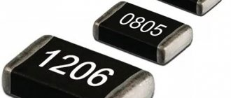
Due to the small size of SMD resistors, it is almost impossible to apply traditional resistor color coding to them.
In this regard, a special marking method has been developed that allows one to determine one or another value of an SMD resistor . The most common marking contains three or four numbers, or two numbers and a letter, called EIA-96. The following is a breakdown of SMD resistors .
Marking with 3 and 4 digits
In this system, the first two or three digits indicate the numerical value of the resistor, and the last digit indicates the multiplier. This last digit indicates the power to which 10 must be raised to obtain the final factor.
A few more examples of determining resistance within this system:
- 450 = 45 x 100 equals 45 ohms
- 273 = 27 x 103 equals 27000 ohms (27 kohms)
- 7992 = 799 x 102 equals 79900 ohms (79.9 kohms)
- 1733 = 173 x 103 equals 173000 ohms (173 kohms)
The letter “R” is used to indicate the position of the decimal point for resistance values below 10 ohms. Thus, 0R5 = 0.5 ohms and 0R01 = 0.01 ohms.
What is a multimeter
A multimeter is a device that can measure AC or DC current, voltage and resistance. It replaces three analog or digital instruments at once: ammeter, voltmeter and ohmmeter. It is also capable of changing the main indicators of any electrical network and ringing it. There are two types of multimeters: digital and analog. The first are portable devices with a display to display the results. Most multimeters on the market today are digital. The second type is already outdated and is no longer popular. It looks like a regular measuring instrument with a graduation scale and an analog needle showing the measurement value.
You might be interested in this Features of the instrumentation and automation profession
Modern digital multimeter
Digital markings
Digital markings contain the exponent (N) of the multiplier (10 N) as the last digit, the remaining two or three are the mantissa of the resistance.
The ratings of passive surface mount components are marked according to certain standards and do not directly correspond to the numbers printed on the package. The article introduces these standards and will help you avoid mistakes when replacing chip components.
The basis for the production of modern electronic and computer equipment is surface mounting technology or SMT technology (SMT - Surface Mount Technology). This technology is distinguished by high automation of printed circuit board installation. A series of miniature leadless electronic components, also called SMD (Surface Mount Devices) components or chip components, have been developed specifically for SMT technology. The sizes of chip components are standardized throughout the world, as are the methods of marking them.
MAIN CHARACTERISTICS OF CHIP RESISTORS Figure 1 shows the appearance of chip resistors, and Tables 1 and 2 show their geometric dimensions and basic technical data. SMD resistor sizes are designated by a four-digit number according to the IEA standard. The designations of the SMD resistors themselves from some foreign manufacturers are given in Table 3. In our country, chip resistors are also produced (P1-12 series).
MARKING OF CHIP RESISTORS Several methods are used for marking chip resistors. The marking method depends on the resistor size and tolerance.
Resistors of size 0402 are not marked.
Resistors with a tolerance of 2%, 5% and 10% of all standard sizes are marked with three numbers, the first two of which indicate the mantissa (that is, the value of the resistor without a multiplier), and the last one is the exponent in base 10 to determine the multiplier.
If necessary, the letter R may be added to significant figures to indicate a decimal point. For example, marking 563 means that the resistor has a nominal value of 56x103 Ohms = 56 kOhms.
The designation 220 means that the resistor value is 22 ohms.
Resistors with a tolerance of 1% of standard sizes from 0805 and above are marked with four digits, the first three of which indicate the mantissa, and the last is an exponent in base 10 to specify the resistor value in Ohms.
The letter R also serves to indicate a decimal point. For example, the marking 7501 means that the resistor has a nominal value of 750x10 Ohms = 7.5 kOhms. Size 0603 1% tolerance resistors are marked using the EIA-96 table below (Table 4) with two numbers and one letter.
The numbers specify the code by which the mantissa is determined from the table, and the letter is the exponent in base 10 to determine the resistor value in Ohms. For example, the marking 10C means that the resistor has a nominal value of 124x102 Ohms = 12.4 kOhms. Literature - Magazine "Electronic Equipment Repair" 2 1999:::
The most common and very widely used element in electronics. is a resistor. This is the element that creates resistance
electric current. Nominal values depend on the accuracy class. It indicates the deviation from the nominal value, which is allowed by the technical conditions. There are three accuracy classes:
- 5% series;
- 10%;
- 20%
For example, if you take a class I resistor with a nominal resistance value of 100 kOhm, then its natural value is in the range from 95 to 105 kOhm. For the same component of accuracy class III, the value will lie in the 20% interval and be equal to 80 or 120 kOhm. Anyone familiar with electrical engineering may recall that there are precision resistors with a 1% tolerance.
The term SMD resistor appeared relatively recently. Surface Mounted Devices can literally be translated into Russian as “surface-mounted device.” Chip resistors, as they are also called, are used in surface-mounted printed circuit boards. They have much smaller dimensions
than their wire counterparts. Square, rectangular or oval shape and low rise allow you to compactly place circuits and save space.
The case has contact pins, which during installation are attached directly to the tracks of the printed circuit board. This design makes it possible to fasten elements without using holes. Thanks to this, the useful area of the board is used with maximum effect, which allows reducing the dimensions of the devices. Due to the fact that the elements are small in size, a high installation density
The main advantage of such elements is the absence of flexible leads, which eliminates the need to drill holes in the printed circuit board. Instead, contact pads are used.
Marking of SMD resistors. Online calculator
First of all, you should pay attention to the relatively new and not everyone is familiar with the EIA-96 marking standard, which consists of three characters - two numbers and a letter. The compactness of writing is compensated by the inconvenience of deciphering the code using a table.
Three-character marking EIA96
EIA-96 planar element coding (SMD)
provides for determining the value of three marking symbols for precision (high-precision) resistors with a tolerance of 1%.
The first two digits - the denomination code from 01
to
96
corresponds to the denomination number from
100
to
976
according to the table.
The third character - a letter - is the multiplier code. Each of the letters X
,
Y
,
Z
,
A
,
B
,
C
,
D
,
E
,
F
,
H
,
R
,
S
corresponds to a multiplier according to the table.
The resistor value is determined by the product of the number and the multiplier. The principle of decoding SMD resistor codes of the E24
and
E48
is much simpler, does not require tables and is described separately below.
An online calculator is offered for decoding resistors EIA-96
,
E24
,
E48
.
Resistance 0 ohm ±1%, EIA-96
as a result of calculation means incorrect input.
Enter the EIA-96
(case insensitive), either 3 digits
E24
or 4 digits
E48
Resistance: 165 ohm ±1%, EIA-96
Table EIA-96
| 100 | 25 | 178 | 49 | 316 | 73 | 562 | |
| 02 | 102 | 26 | 182 | 50 | 324 | 74 | 576 |
| 03 | 105 | 27 | 187 | 51 | 332 | 75 | 590 |
| 04 | 107 | 28 | 191 | 52 | 340 | 76 | 604 |
| 05 | 110 | 29 | 196 | 53 | 348 | 77 | 619 |
| 06 | 113 | 30 | 200 | 54 | 357 | 78 | 634 |
| 07 | 115 | 31 | 205 | 55 | 365 | 79 | 649 |
| 08 | 118 | 32 | 210 | 56 | 374 | 80 | 665 |
| 09 | 121 | 33 | 215 | 57 | 383 | 81 | 681 |
| 10 | 124 | 34 | 221 | 58 | 392 | 82 | 698 |
| 11 | 127 | 35 | 226 | 59 | 402 | 83 | 715 |
| 12 | 130 | 36 | 232 | 60 | 412 | 84 | 732 |
| 13 | 133 | 37 | 237 | 61 | 422 | 85 | 750 |
| 14 | 137 | 38 | 243 | 62 | 432 | 86 | 768 |
| 15 | 140 | 39 | 249 | 63 | 442 | 87 | 787 |
| 16 | 143 | 40 | 255 | 64 | 453 | 88 | 806 |
| 17 | 147 | 41 | 261 | 65 | 464 | 89 | 825 |
| 18 | 150 | 42 | 267 | 66 | 475 | 90 | 845 |
| 19 | 154 | 43 | 274 | 67 | 487 | 91 | 866 |
| 20 | 158 | 44 | 280 | 68 | 499 | 92 | 887 |
| 21 | 162 | 45 | 287 | 69 | 511 | 93 | 909 |
| 22 | 165 | 46 | 294 | 70 | 523 | 94 | 931 |
| 23 | 169 | 47 | 301 | 71 | 536 | 95 | 953 |
| 24 | 174 | 48 | 309 | 72 | 549 | 96 | 976 |
| 0.001 | |
| Y or R | 0.01 |
| X or S | 0.1 |
| A | 1 |
| B or H | 10 |
| C | 100 |
| D | 1000 |
| E | 10000 |
| F | 100000 |
Three-character marking E24. Tolerance 5%
Three-digit marking. The first two digits are the denomination number. The third digit is the decimal logarithm of the multiplier. 0=lg1, multiplier 1. 1=lg10, multiplier 10. 2=lg100, multiplier 100. 3=lg1000, multiplier 1000. Etc., according to the number of zeros of the multiplier. The product of the number and the multiplier will determine the resistor value. For this article, use the calculator window above as for EIA-96.
Brief technical characteristics and application
SMD LEDs with markings 5050, 3528 and 5630 (5730) are popular. It is in the LED strip that such SMD crystals are used, which is why they have become widespread.
But there are quite a lot of other standard sizes. Here are the main ones (brief descriptions and areas of application, the most common of them):
0603. Power 1.9 - 2.3 watts. Commonly used in car dashboards and screen backlights in some mobile phones.
2835. Power 0, 2 – 1. Used in LED lamps, pocket and tactical flashlights. Good energy saver. But mostly only white.
Not to be confused with the 3528, which is older and not as energy efficient.
Which side to count the stripes on the resistor?
The resistance of the resistor is determined by the first color rings:
- For elements with three stripes, the first two colors are numbers, and the third color is the multiplier.
- For elements with four stripes, the first two colors are numbers, the third color is the multiplier, and the fourth color is the permissible deviation of the resistor resistance from its nominal value.
- For elements with five stripes, the first three colors are numbers, the fourth color is the multiplier, and the fifth color is the permissible deviation of the resistor resistance from its nominal value.
- For elements with six stripes, the first three colors are numbers, the fourth color is the multiplier, the fifth color is the permissible deviation of the resistor resistance from its nominal value, and the sixth is the temperature coefficient.
The color markings on resistors are read from left to right. In this case, you need to correctly determine the left side. As a rule, the first stripe is applied closer to one of the resistor terminals. If the element is small in size and it is impossible to maintain the required proportions for marking delimitation, then the counting is based on the color stripe, which is the widest in comparison with the others.
Additionally, it can be noted that silver and gold colors are never used to indicate the first stripes on resistors. And, as can be seen from the calculation tables, digital values are not specified for these colors.
Decoding resistor coding online
Keeping in memory or searching for tables for determining the encoding value of SMD resistors is quite difficult and time-consuming. There are various services on the Internet for automatically selecting element designations. It is very easy to decipher the markings of SMD resistors online. The determination is made on the website using a special script. It is enough to find a suitable SMD resistor calculator online, enter the code designation in the input field, and the program will determine the type and value of the resistance.
With the help of such services, the reverse conversion is also possible. Resistance and units of measurement (Ohm, kilo-ohm, mega-ohm) are entered in the required fields. After pressing the button showing the result, the corresponding resistor marking will appear on the screen.
https://youtube.com/watch?v=nYxLlh8cQ04
Types of SMD capacitors
Every radio amateur needs to understand the types of capacitors mounted using the surface-mount method. Such products may differ not only in capacity, but also in voltage, so ignoring the conditions for using parts can lead to their failure.
Electrolytic components
Electrolytic SMD capacitors do not differ fundamentally from standard products. Such electronic components most often take the form of barrels, in which a thin metal rolled into a cylinder is located under an aluminum housing, and a solid or liquid electrolyte is located between it.
Electrolytic SMD capacitors
The main difference between such a part and a standard electrolytic cell is that its contacts are mounted on a flat dielectric substrate. Such products are very reliable in operation, especially convenient when it is necessary to install a new product with minimal time investment.
In addition, during soldering the product does not overheat, which is very important for electrolytic capacitors
Ceramic components
In ceramic elements, porcelain or similar inorganic materials are used as a dielectric. The main advantage of such products is their resistance to high temperatures and the ability to produce products of extremely small sizes.
Important! SMD ceramic capacitors are also installed by soldering onto a printed circuit board. Visually, such an element, as a rule, resembles a small brick to which contact pads are soldered at the ends
Visually, such an element, as a rule, resembles a small brick to which contact pads are soldered at the ends
Visually, such an element, as a rule, resembles a small brick to which contact pads are soldered at the ends.
Ceramic SMD capacitors
Unlike radio components of standard sizes, SMD elements of small size are first glued to the board, and only then the leads are soldered. In production, ceramic products of this type are installed by special automatic machines.
Marking of tantalum SMD capacitors
Tantalum SMD capacitors are resistant to increased mechanical loads. Such products can also be made in the form of a small parallelepiped, to which contact leads are soldered on the sides. Tantalum is a very durable metal with high ductility. Foil made of this material can have a thickness of hundredths of a millimeter.
For your information! Due to the presence of certain physical properties based on tantalum, it is possible to produce radio components of the highest precision.
Tantalum capacitors
Tantalum capacitors, as a rule, have small housing sizes, so it is not always possible to apply full markings to products made in an “A” size housing. Knowing the designation features of radio components of this type, you can easily determine the rating of the product. The maximum permissible voltage in volts for tantalum products is indicated in Latin letters:
- G - 4;
- J - 6.3;
- A - 10;
- C - 16;
- D - 20;
- E - 25;
- V - 35;
- T - 50.
Note! The capacity of the products is indicated in microfarads after the letter “μ”, and the positive contact is indicated with a thick line
Table of SMD resistor codes and their values
| Code smd | Meaning | Code smd | Meaning | Code smd | Meaning | Code smd | Meaning |
| R10 | 0.1 Ohm | 1R0 | 1 ohm | 100 | 10 ohm | 101 | 100 Ohm |
| R11 | 0.11 Ohm | 1R1 | 1.1 Ohm | 110 | 11 ohm | 111 | 110 Ohm |
| R12 | 0.12 Ohm | 1R2 | 1.2 Ohm | 120 | 12 ohm | 121 | 120 Ohm |
| R13 | 0.13 Ohm | 1R3 | 1.3 Ohm | 130 | 13 ohm | 131 | 130 Ohm |
| R15 | 0.15 Ohm | 1R5 | 1.5 Ohm | 150 | 15 ohm | 151 | 150 Ohm |
| R16 | 0.16 Ohm | 1R6 | 1.6 Ohm | 160 | 16 ohm | 161 | 160 Ohm |
| R18 | 0.18 Ohm | 1R8 | 1.8 Ohm | 180 | 18 ohm | 181 | 180 Ohm |
| R20 | 0.2 Ohm | 2R0 | 2 ohm | 200 | 20 ohm | 201 | 200 Ohm |
| R22 | 0.22 Ohm | 2R2 | 2.2 Ohm | 220 | 22 Ohm | 221 | 220 Ohm |
| R24 | 0.24 Ohm | 2R4 | 2.4 Ohm | 240 | 24 ohm | 241 | 240 Ohm |
| R27 | 0.27 Ohm | 2R7 | 2.7 Ohm | 270 | 27 Ohm | 271 | 270 Ohm |
| R30 | 0.3 ohm | 3R0 | 3 ohm | 300 | 30 ohm | 301 | 300 Ohm |
| R33 | 0.33 Ohm | 3R3 | 3.3 Ohm | 330 | 33 Ohm | 331 | 330 Ohm |
| R36 | 0.36 Ohm | 3R6 | 3.6 Ohm | 360 | 36 Ohm | 361 | 360 Ohm |
| R39 | 0.39 Ohm | 3R9 | 3.9 Ohm | 390 | 39 Ohm | 391 | 390 Ohm |
| R43 | 0.43 Ohm | 4R3 | 4.3 Ohm | 430 | 43 Ohm | 431 | 430 Ohm |
| R47 | 0.47 Ohm | 4R7 | 4.7 Ohm | 470 | 47 Ohm | 471 | 470 Ohm |
| R51 | 0.51 Ohm | 5R1 | 5.1 Ohm | 510 | 51 Ohm | 511 | 510 Ohm |
| R56 | 0.56 Ohm | 5R6 | 5.6 Ohm | 560 | 56 Ohm | 561 | 560 Ohm |
| R62 | 0.62 Ohm | 6R2 | 6.2 Ohm | 620 | 62 Ohm | 621 | 620 Ohm |
| R68 | 0.68 Ohm | 6R8 | 6.8 Ohm | 680 | 68 Ohm | 681 | 680 Ohm |
| R75 | 0.75 Ohm | 7R5 | 7.5 Ohm | 750 | 75 Ohm | 751 | 750 Ohm |
| R82 | 0.82 Ohm | 8R2 | 8.2 Ohm | 820 | 82 Ohm | 821 | 820 Ohm |
| R91 | 0.91 Ohm | 9R1 | 9.1 Ohm | 910 | 91 Ohm | 911 | 910 Ohm |
| Code smd | Meaning | Code smd | Meaning | Code smd | Meaning | Code smd | Meaning |
| 102 | 1 kOhm | 103 | 10 kOhm | 104 | 100 kOhm | 105 | 1 MOhm |
| 112 | 1.1 kOhm | 113 | 11 kOhm | 114 | 110 kOhm | 115 | 1.1 MOhm |
| 122 | 1.2 kOhm | 123 | 12 kOhm | 124 | 120 kOhm | 125 | 1.2 MOhm |
| 132 | 1.3 kOhm | 133 | 13 kOhm | 134 | 130 kOhm | 135 | 1.3 MOhm |
| 152 | 1.5 kOhm | 153 | 15 kOhm | 154 | 150 kOhm | 155 | 1.5 MOhm |
| 162 | 1.6 kOhm | 163 | 16 kOhm | 164 | 160 kOhm | 165 | 1.6 MOhm |
| 182 | 1.8 kOhm | 183 | 18 kOhm | 184 | 180 kOhm | 185 | 1.8 MOhm |
| 202 | 2 kOhm | 203 | 20 kOhm | 204 | 200 kOhm | 205 | 2 MOhm |
| 222 | 2.2 kOhm | 223 | 22 kOhm | 224 | 220 kOhm | 225 | 2.2 MOhm |
| 242 | 2.4 kOhm | 243 | 24 kOhm | 244 | 240 kOhm | 245 | 2.4 MOhm |
| 272 | 2.7 kOhm | 273 | 27 kOhm | 274 | 270 kOhm | 275 | 2.7 MOhm |
| 302 | 3 kOhm | 303 | 30 kOhm | 304 | 300 kOhm | 305 | 3 MOhm |
| 332 | 3.3 kOhm | 333 | 33 kOhm | 334 | 330 kOhm | 335 | 3.3 MOhm |
| 362 | 3.6 kOhm | 363 | 36 kOhm | 364 | 360 kOhm | 365 | 3.6 MOhm |
| 392 | 3.9 kOhm | 393 | 39 kOhm | 394 | 390 kOhm | 395 | 3.9 MOhm |
| 432 | 4.3 kOhm | 433 | 43 kOhm | 434 | 430 kOhm | 435 | 4.3 MOhm |
| 472 | 4.7 kOhm | 473 | 47 kOhm | 474 | 470 kOhm | 475 | 4.7 MOhm |
| 512 | 5.1 kOhm | 513 | 51 kOhm | 514 | 510 kOhm | 515 | 5.1 MOhm |
| 562 | 5.6 kOhm | 563 | 56 kOhm | 564 | 560 kOhm | 565 | 5.6 MOhm |
| 622 | 6.2 kOhm | 623 | 62 kOhm | 624 | 620 kOhm | 625 | 6.2 MOhm |
| 682 | 6.8 kOhm | 683 | 68 kOhm | 684 | 680 kOhm | 685 | 6.8 MOhm |
| 752 | 7.5 kOhm | 753 | 75 kOhm | 754 | 750 kOhm | 755 | 7.5 MOhm |
| 822 | 8.2 kOhm | 823 | 82 kOhm | 824 | 820 kOhm | 815 | 8.2 MOhm |
| 912 | 9.1 kOhm | 913 | 91 kOhm | 914 | 910 kOhm | 915 | 9.1 MOhm |
Standard sizes of SMD resistors
Basically, the term frame size includes the size, shape and terminal configuration (package type) of any electronic component. For example, the configuration of a conventional chip that has a flat package with double-sided pins (perpendicular to the plane of the base) is called DIP.
SMD resistor sizes are standardized, and most manufacturers use the JEDEC standard. The size of SMD resistors is indicated by a numerical code, for example, 0603. The code contains information about the length and width of the resistor. So in our example code 0603 (in inches) the body length is 0.060 inches by 0.030 inches wide.
Organizer for SMD components Great for storing 1206/0805/0603/0402/0201…
Soldering station Eruntop 8586D Electric soldering iron + hair dryer for SMD, dual digital display…
Set of SMD resistors 1206 100 pcs., 0R...10M 1/2 W, 0, 1, 10, 100, 150, 220, 330...
Professional SMD component tester Digital tester for checking SMD resistors, capacitors, diodes...
The same resistor size in the metric system will have code 1608 (in millimeters), respectively, the length is 1.6 mm, the width is 0.8 mm. To convert dimensions to millimeters, simply multiply the size in inches by 25.4.
SMD resistor sizes and their power
The size of the SMD resistor depends mainly on the required power dissipation. The following table lists the sizes and specifications of the most commonly used SMD resistors.
SMD resistors
SMT technology (from the English Surface Mount Technology) was developed with the aim of reducing the cost of production, increasing the efficiency of manufacturing printed circuit boards using smaller electronic components: resistors, capacitors, transistors, etc. Today we will look at one of these types of resistors - the SMD resistor.
SMD resistors are miniature resistors designed for surface mounting. SMD resistors are significantly smaller than their traditional counterpart. They are often square, rectangular or oval shaped, with a very low profile.
Instead of the lead wires of conventional resistors that are inserted into holes on a printed circuit board, SMD resistors have small contacts that are soldered to the surface of the resistor body. This eliminates the need to make holes in the printed circuit board, and thus allows more efficient use of its entire surface.
What are the labeling standards?
The markings that are applied to the body of SMD elements, as a rule, differ from their brand names. The reason is trivial - lack of space due to the miniature size of the case. The problem is especially relevant for electronic electronic devices, which are placed in packages with six or fewer leads.
These are miniature diodes, transistors, voltage stabilizers, amplifiers, etc. To figure out “what is what”, a real examination is required, because it is very difficult to identify the type of ERE using one marking code without additional information. More than 20 years have passed since the appearance of the first SMD devices.
Despite all attempts at standardization, manufacturing companies are still stubbornly inventing new types of SMD cases and haphazardly assigning marking codes to their elements.
It’s not so bad that the applied symbols do not even closely resemble the name of the ERE; the worst thing is that there are cases of “plagiarism” when the same codes are assigned to functionally different devices from different companies.
| Type | Name of ERE | Foreign name |
| A1 | N-channel field effect transistor | Feld-Effect Transistor (FET), N-Channel |
| A2 | Double-gate N-channel field-effect transistor | Tetrode, Dual-Gate |
| A3 | Set of N-channel field effect transistors | Double MOSFET Transistor Array |
| B1 | Field-effect P-channel transistor | MOS, GaAs FET, P-Channel |
| D1 | One diode for wide application | General Purpose, Switching, PIN-Diode |
| D2 | Two widely used diodes | Dual Diodes |
| D3 | Three widely used diodes | Triple Diodes |
| D4 | Four widely used diodes | Bridge, Quad Diodes |
| E1 | One pulse diode | Rectifier Diode |
| E2 | Two pulse diodes | Dual |
| E3 | Three pulse diodes | Triple |
| E4 | Four pulse diodes | Quad |
| F1 | One Schottky diode | AF-, RF-Schottky Diode, Schottky Detector Diode |
| F2 | Two Schottky diodes | Dual |
| F3 | Three Schottky diodes | Triple |
| F4 | Four Schottky diodes | Quad |
| K1 | “Digital” NPN transistor | Digital Transistor NPN |
| K2 | A set of “digital” NPN transistors | Double Digital NPN Transistor Array |
| L1 | “Digital” PNP transistor | Digital Transistor PNP |
| L2 | A set of “digital” PNP transistors | Double Digital PNP Transistor Array |
| L3 | Set of “digital” transistors | PNP, NPN | Double Digital PNP-NPN Transistor Array |
| N1 | Bipolar LF transistor NPN (f < 400 MHz) | AF-Transistor NPN |
| N2 | Bipolar RF transistor NPN (f > 400 MHz) | RF Transistor NPN |
| N3 | High voltage NPN transistor (U > 150 V) | High-Voltage Transistor NPN |
| N4 | “Superbeta” NPN transistor (r“21e > 1000) | Darlington Transistor NPN |
| N5 | NPN transistor set | Double Transistor Array NPN |
| N6 | Low noise NPN transistor | Low-Noise Transistor NPN |
| 01 | Operational amplifier | Single Operational Amplifier |
| 02 | Comparator | Single Differential Comparator |
| P1 | Bipolar LF transistor PNP (f < 400 MHz) | AF-Transistor PNP |
| P2 | RF bipolar transistor PNP (f > 400 MHz) | RF Transistor PNP |
| P3 | High voltage PNP transistor (U > 150 V) | High-Voltage Transisnor PNP |
| P4 | “Superbeta” PNP transistor (p21e > 1000) | Darlington Transistor PNP |
| P5 | PNP Transistor Set | Double Transistor Array PNP |
| P6 | Set of transistors PNP, NPN | Double Transistor Array PNP-NPN |
| S1 | One suppressor | Transient Voltage Suppressor (TVS) |
| S2 | Two suppressors | Dual |
| T1 | Reference voltage source | “Bandgap”, 3-Terminal Voltage Reference |
| T2 | Voltage regulator | Voltage Regulator |
| T3 | Voltage detector | Voltage Detector |
| U1 | FET amplifier | GaAs Microwave Monolithic Integrated Circuit (MMIC) |
| U2 | Bipolar amplifier NPN | Si-MMIC NPN, Amplifier |
| U3 | Bipolar amplifier PNP | Si-MMIC PNP, Amplifier |
| V1 | One varicap (varactor) | Tuning Diode, Varactor |
| V2 | Two varicaps (varactors) | Dual |
| Z1 | One zener diode | Zener Diode |
Main sizes of SMD resistors
The limited size of the visible surface explains the minimum number of marking elements. For SMD resistors, the sizes are determined by a digital combination of 4 (5) characters. The first half of the number indicates the length, the second half the width. Previously, the measurement result was used in inches with rounding of the result. Nowadays, the metric system (mm) is more commonly used, which means relatively better accuracy.
Examples of notation
| Standard size | System (metric, inch) | Length Width | |
| In inches | In millimeters | ||
| 0201M | M | 0,0079/0,0039 | 2/1 |
| 0805 | D | 0,08/0,05 | 2,032/1,27 |
| 2550M | M | 0,098/0,197 | 2,5/5 |
| 1020 | D | 0,1/0,2 | 2,54/5,08 |
The size of a capacitor, an LED, or an assembly of several resistors is indicated in the same way. As a rule, the thickness is not indicated. This size and other product parameters are given in the accompanying documentation.
Relatively large products can be measured with a regular ruler. Next, use the reference data to determine the appropriate size. However, as it decreases, solving the problem using available means is much more difficult. You have to use a micrometer, magnifying glass or specialized magnifying equipment.
For your information. Marking indicating the standard size is not applied to the body of the SMD resistor.
In order to save space on the printed circuit board, individual resistor models (assemblies) are created with contact pins on the bottom or top pad. This solution provides a connection to the electrical circuit directly at the installation point. The second contact is connected with a separate conductor to a specific section of the circuit.
It is impossible to list all standard sizes within one publication. Specialized enterprises produce various modifications. In some situations, they create unique products according to the customer’s special technical specifications. “Conventional” rectangular and round cross-sectional shapes are used (MELF series).
Electrical resistance is not determined by the size of the chip. Products are produced in a series of ratings from zero value (jumper) to several MOhms.
The miniature pad is suitable for indicating electrical resistance using standard markings (3-4 characters):
- the first digits are the base denomination for calculation;
- the last one is the number of zeros;
- R – comma separator.
Examples:
- 202 – 20*100 = 2 kOhm;
- 4401 – 440*10 = 4.4 kOhm;
- 4R42 – 4.4*100 = 440 Ohms.
EIA standard markings are also used. The digital code corresponds to a specific denomination. The Latin letter denotes the multiplier. This method is used in the manufacture of precision products with a permissible deviation of no more than 1%.
Parameters that can be found in the detailed description (example for SMD resistor size 0402):
- Length x width – 0.1 x 0.5 mm;
- Thickness – 0.35 mm;
- Electrical resistance (range) – from 1 Ohm to 3 MOhm;
- Nominal accuracy – 1% (5%) for category F (L);
- Power – 0.062 W;
- Operating (maximum) voltage – 50 (100) V;
- Temperature range during operation is from -55°C to 125°C.
The typical dimensions of chip resistors determine the power dissipation for which the corresponding element is designed. To clarify this most important parameter, the methods discussed above for measuring dimensions are used. After this, the permissible power is specified using the reference table (standard size - W):
- 0201 – 0,05;
- 0805 – 0.125 or 0.25;
- 1210 – 0,5;
- 2512 – 1 or 1.5 or 2;
- 1218 – 1.
The list shows that some resistors are produced in different designs. It is recommended to clarify the permissible power in order to exclude excessive current load and damage to the element due to thermal heating. When choosing, a certain technological reserve is made for this parameter.
When working with high-frequency (pulse) signals, it is necessary to take into account the influence of reactive components of the structure.
Principles of digital marking of SMD resistors.
Smd resistor: table of sizes and powers. Determining resistor parameters by code - examples and online calculator.On the previous page we looked at methods for determining the parameters of standard color-coded output resistors.
SMD resistors are the same as regular fixed resistors, only intended for purely surface mounting on a printed circuit board. SMD resistors can come in a variety of shapes, but in general, they are significantly smaller than their traditional lead-based counterparts. Due to the small size of such resistors, it is difficult to apply traditional color stripes to them, so a digital marking method has been developed, which is applied to the housings of SMD elements and consists of three or four numbers, or two numbers and a letter (EIA-96 marking).
With three-digit marking, the first two digits indicate the numerical value of the resistance in Ohms, the third digit determines the multiplier. The multiplier is the number 10 raised to the power of the third digit.
As an example, here are simple calculations: ♦ Marking – 240 : then R = 22 × 100 , which equals 22 Ohms; ♦ Marking – 273 : then R = 27 × 103 , which equals 27000 Ohms or 27 kOhms. For resistance ratings below 10 Ohms, the letter R is entered into the marking, which indicates the position of the decimal point in the resistor resistance value. In this case there is no multiplier. Let us explain with examples: ♦ Marking – 5R6 : then R = 5.6 Ohm ; ♦ Marking – R12 : then R = 0.12 Ohm . Typically, the error tolerance for three-digit resistors is 5% .
For SMD resistors with an error tolerance of 1%, four-digit digital marking is used . Here everything happens by analogy with three-digit marking, only the numerical value of resistance in Ohms is indicated by the first 3 digits, and the fourth is the power of the multiplier, where the multiplier is the number 10 raised to the power of the fourth digit. For resistance ratings below 100 Ohms, the letter R is entered into the marking, which indicates the position of the decimal point in the resistor resistance value. In this case there is also no multiplier. And again, a few examples: ♦ Marking – 3301 : then R = 330 × 101 , which equals 3300 Ohm or 3.3 kOhm; ♦ Marking – 5R60 : then R = 5.6 Ohm .
For SMD resistors with a resistance error tolerance of 1%, a more compact three-digit marking that complies with the EIA-96 standard . Here, the first two digits represent a code that gives a three-digit resistance number, and the third digit is a letter that determines the multiplier (Fig. 1).
Fig. 1 Encoding table for SMD resistors according to the EIA-96 standard
Let's give a couple more examples: ♦ Marking – 01Y : then R = 100 × 0.01 , which equals 1 Ohm; ♦ Marking – 29V : then R = 196 × 10 , which equals 1.96 kOhm.
Now let’s spice up the material covered with a calculator.
Online calculator for determining the parameters of SMD resistors using digital markings
The power of SMD chip resistors can be determined based on their overall dimensions and reference data provided by the manufacturer. An example of such a correspondence table is shown in Fig. 2.
Fig. 2 Table of correspondence between the overall dimensions of SMD resistors and their power