Characteristics of popular horizontal boring machines
A horizontal boring machine is used for boring holes, drilling, turning cylindrical parts, processing the ends of products, milling, countersinking, threading and performing many other operations.
This variety allows you to complete a full cycle in creating a product from a blank without using any other devices, which is very convenient for multi-batch production.
Horizontal boring machine 2620
A distinctive feature of this type of production equipment that carries out axial feed is the presence of a spindle (horizontal or vertical).
One of the cutting tools is fixed in the spindle - a milling cutter, a boring bar with a set of cutters, a drill, a countersink, etc. All operating parameters and overall dimensions of the machine are determined by the diameter of the spindle.
Horizontal boring machine 2620A
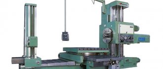
The 2620A horizontal boring machine is designed for processing body parts that have precise holes connected to each other by precise distances.
The largest weight of the workpiece (with a uniformly distributed load on the machine table) is 2000 kg.
This machine can be used to perform: drilling, boring, countersinking, reaming holes, turning ends with a radial support, milling with end mills and cutting internal threads with a boring spindle, as well as threading with a radial support during longitudinal movement of the table.
Due to the fact that the machine can be used in various industries for various operations, for processing various materials, maintenance of the machine should be carried out taking into account the specifics of their operation.
About the design features
The design features and the workpieces used make it possible to distinguish the installation for a special, universal purpose.
Horizontal boring machines 2620 are:
- Diamond boring machines.
- Jig boring machines.
- Horizontal view.
The horizontal machine has three versions:
- with two directions of movement;
- with movement in one direction;
- lack of movement.
The spindle is moving, which means that work is starting, shaping is taking place, when workpieces are processed using a horizontal boring machine 2620. Both the tool itself and the workpiece can be fed. The specific option is determined by the technology used. Processing is not complete without additional movements:
- Using guides when moving the steady rest.
- Connection between the rest and the rear pillar.
- Movement of the table across or along.
- Spindle head running vertically. 2620V designs also have this option. This makes the technical characteristics high, and relative to the 2620a option.
Most of the machines are equipped with a rotary table, with spindles of 125 mm diameter. The tables move both transversely and lengthwise. Among the important additions are the A-pillars, which have no movement.
With a 125 mm spindle diameter, the racks move without problems in one or several directions. But most often there are models of horizontal boring machines 2620 with stationary components.
Machine passport 2620
This operating manual “ Machine 2620 Passport ” contains information necessary both for the maintenance personnel of this machine and for the employee directly involved in working on this machine. This manual is an electronic version in PDF format of the original paper version. This documentation contains the Certificate and Manual (instructions) for the operation of the horizontal boring machine 2620.
CONTENT
PURPOSE UNPACKING AND TRANSPORTATION INSTALLATION AND INSTALLATION
- Foundation
- Machine installation
- Machine installation
PREPARATION FOR INITIAL START-UP PASSPORT
- Passport details
- Machine mechanics
- Machine equipment
- Machine controls
- Machine kinematics
- DESCRIPTION
- General structure of the machine
- Design of machine components
- bed
- Headstock
- Table
- Rear pillar
- Electrical equipment on the machine
- Accessories
- Optical devices
- Electrical equipment
- Machine kinematics
DESCRIPTION
- Main movement chain
- Feed chain
- Machine control
- Rotation
- Moving the moving parts of the machine
- Clamps of moving parts of the machine
- Machine locks
LUBRICATION OPERATING INSTRUCTIONS
- Measuring the movements of the moving parts of the machine
- Optical devices
- Precise stop mechanism based on coordinates
- Operating principle of precision stop mechanisms
- Setting the precision stop indicator scale
- Setting up rods with stops
- Threading
ADJUSTMENT INSTRUCTIONS
- Adjusting the spindle bearings
- Hollow spindle (models 2620 and 2620A)
- Hollow spindle (models 2622 and 2622A)
- Faceplate spindle
- Boring spindle
- Adjusting the gap in the screw pair of the radial support movement drive (for machines models 2620 and 2620A)
- Adjusting the thrust ball bearings of the propeller support in the tail section
- Adjusting the central overload fuse
- Adjustment procedure
- Adjustment of clamping devices
- Headstock Clamp
- Turntable Clamp
- Adjusting the clamps
- Adjusting the table rotation angle reference device every 90°
REPAIR INSTRUCTIONS
- Machine repair
- Special instructions about possible errors during repairs
download the passport of the horizontal boring machine 2620 in good quality from the link below.
Boring machines: purpose and areas of use
Such equipment can be used to perform such operations as:
- thread cutting, internal and external;
- drilling blind and through holes;
- countersinking;
- trimming the ends of workpieces;
- face and cylindrical milling, etc.
Most often, this equipment is used for finishing or semi-finishing. However, it happens that with its use they also produce finishing. The part body is rarely processed on such machines, but sometimes this operation is still performed. Repair of a boring machine is carried out using approximately the same technology as a turning machine. The same applies to operating features. The design of these two types of machines is similar. Like many other special types of equipment designed for processing metal and wood workpieces, a boring machine was once designed on the basis of a lathe.
Technical re-equipment of a horizontal boring machine
- » onclick=»window.open(this.href,'win2′,'status=no,toolbar=no,scrollbars=yes,titlebar=no,menubar=no,resizable=yes,width=640,height=480,directories =no,location=no'); return false;" rel=”nofollow”> Print
Project goals
The goal of the project is to replace physically and morally obsolete equipment:
- replacement of the G-D circuit with a tube amplifier of the electric feed drive with a modern digital DC-DC converter;
- replacement of the relay contactor circuit for controlling and selecting moving parts with a logical device of the LOGO top.
Description of the object
A 2620V horizontal boring machine is installed in the TsLMK workshop of EVRAZ NTMK OJSC. The machine was released in 1962. The machine is powered from the RP-10 distribution point with a voltage of 0.4 kV. The power input circuit remains unchanged and cannot be reconstructed
within the framework of this project. Installed power of electrical equipment is 21 kW.
The machine includes:
- feed motor;
- electric machine amplifier (EMA);
- unit engine;
- main spindle rotation drive;
- spindle head mechanism lubrication pump motor;
- table rotation motor;
- gear pump motor.
The main drive of rotation of the spindle and faceplate is carried out from a two-speed asynchronous motor through a gear reducer. Dynamic braking is used for quick stops and when steering steering turns.
The drive for the supply and installation movements of the moving parts is carried out from a DC motor operating according to a generator-motor (G-E) circuit with a tube amplifier. The EMU is used as a generator. The speed reference is supplied from an independent current source with voltage Uset = 0.3 -120 V. To measure the actual speed, a PT-1 tachogenerator is installed on the motor shaft. Comparison of the actual speed with the set one is made by subtracting the tachogenerator voltage from the voltage value of the independent source. The resulting difference, proportional to the deviation of the actual speed from the set one, is fed to the input of a tube amplifier, to the output of which two EMU windings are connected. The control circuit provides a speed control range for the feed motor of 1 - 800, taking into account flow weakening of 1 - 1800. The feed drive is controlled and the selection of moving parts is carried out by a relay contactor control circuit. The moving parts are connected to the feed motor using electromagnetic couplings.
Scope of reconstruction:
- Complete replacement of the G-D circuit with a tube amplifier for the electric drive;
- Replacement of the relay contactor circuit for controlling and selecting moving parts;
The following technical solutions are used:
- the existing G-D circuit with a tube amplifier, the control circuit and selection of moving parts, and the tachogenerator are completely dismantled;
- A new control cabinet for the electric drive of supply and control and selection of moving parts (AM) is being developed, which has a degree of protection of IP54. The cabinet uses a modern Sinamics DCM digital converter and LOGO logic modules. The cabinet is installed next to the existing control cabinet;
- to reduce the voltage in the power circuit of the converter, a transformer (type TSZP-10) is used, installed next to the AM control cabinet;
- circuit solutions are used that ensure the operation of the machine in accordance with the passport for the 2620V horizontal boring machine and do not lead to a change in the control method from the point of view of the machine operator.
Technical characteristics of the machine 2620A
The technical characteristics of the machine are the main indicator of the suitability of the machine to perform certain jobs. For horizontal boring machines, the main characteristics are:
- retractable spindle diameter
- table working surface dimensions
- greatest longitudinal movement of the spindle
- spindle revolutions per minute
Below is a table with the technical characteristics of the 2620A horizontal boring machine. More detailed technical characteristics of the horizontal boring machine can be found in the passport of the machine 2620A
| Quantities | ||
| Diameter of retractable boring spindle | mm | 90 |
| Dimensions of the working surface of the table | mm | 1120x900 |
| Maximum longitudinal movement of the spindle | mm | 1150 |
| Maximum lateral movement of the table | mm | 1000 |
| The price of one division of the dial scale | mm | 0,025 |
| Fast table movement | m/min | 2,2 |
| Quick installation circular movement of the table | rpm | 2,8 |
| The price of one division of the table rotation dial scale | hail | 0,5 |
| Maximum axial movement of the spindle | mm | 710 |
| Fast spindle movement | Mmm | 3,48 |
| Maximum movement of the radial support of the faceplate | mm | 170 |
| Rapid installation movement of the radial caliper | m/min | 1,39 |
| Maximum vertical movement of the spindle head | mm | 1000 |
| Fast installation movement of spindle head | m/min | 2,2 |
| Rotation speed of the main movement motor | rpm | 1500/3000 |
| Main motor power | kW | 7,5/10 |
| Overall dimensions of the machine (LxWxH) | mm | 5510x3200x3012 |
| Machine weight | kg | 12000 |
Attention! The technical specifications given in the above table are for reference only. Machines produced by different manufacturers and in different years may have characteristics that differ from those given in the table.
Jig boring machines
The main feature of jig boring machines (Fig. 3) is the high precision of processing parts.
Figure 3. Jig boring machine.
Increased processing accuracy is achieved through the use of various high-precision mechanisms for calculating the coordinates along which the cutter moves. There are several main methods for calculating coordinates implemented on jig boring machines:
- inductive;
- mechanical;
- optical-mechanical;
- electronic.
The spindle on the machines of this subgroup is located vertically. But sometimes there are models with a horizontal spindle. The spindle head, in addition to changing the speed and direction of rotation, also carries out a working feed, increasing or decreasing the depth of penetration of the cutter into the part.
The table has two degrees of freedom. A part fixed on a table can move in the longitudinal and transverse directions. Moreover, the magnitude of these movements is controlled with high accuracy by the coordinate system.
Also, on jig boring machines, in addition to performing the entire range of operations characteristic of boring group machines, marking operations are performed.
Boring machine 2620 technical specifications
Information about the manufacturer of horizontal boring machine 2620B
The manufacturer of horizontal boring machines, models 2620B, is the Ivanovo Heavy Machine Tool Plant , founded in 1953.
On November 21, 1958, the first stage of the Ivanovo Boring Machine Plant was put into operation. In 1958, the production of units and components for the Leningrad Machine Tool Plant named after Sverdlov was launched. Over time, the plant began producing simple horizontal boring machines according to the drawings of the same plant. Having equipped production with the necessary base, machine tool builders switched to the production of more complex products - machining centers (MC).
Machine tools produced by the Ivanovo Heavy Machine Tool Plant IZTS
2620V universal horizontal boring machine. Purpose and scope
Start of serial production of the machine in 1973. The machine is currently not in production.
The universal horizontal boring machine 2620B is designed for processing body parts made of ferrous and non-ferrous metals that have precise holes connected to each other by precise interaxial distances.
The largest weight of the workpiece (with a uniformly distributed load on the machine table) is 3000 kg.
The machines can perform: drilling, boring, countersinking, reaming holes, turning ends with a radial support, milling with end mills and cutting internal threads with a boring spindle, as well as threading with a radial support during longitudinal movement of the table.
Design features of the 2620V machine
The machine model 2620B is designed for processing body parts; it has a fixed front stand, a rotary table with longitudinal and transverse movement relative to the spindle axis, and a faceplate with a radial support. The machine can be used for drilling, countersinking, boring and reaming holes interconnected by precise coordinates, turning ends, turning grooves and protrusions with a radial support when feeding the table, as well as continuous milling with bypass along a rectilinear contour using a switch on the control panel. The machine is characterized by increased rigidity and vibration resistance of the spindle system. The retractable boring spindle with a hard nitrided surface rides on long, hardened steel guide bushings for increased rigidity, vibration resistance and long-term accuracy. The spindle is mounted on precision rolling bearings. The spindle speed is switched by a single-handle selective mechanism with a special device that automatically protects the ends of the teeth from wear during switching.
Horizontal boring machine 2620VF1, 2A620
Machine after major overhaul 12 month warranty
2620, 2620A, 2622, 2622A horizontal boring machines. Purpose and scope
Machines models 2620, 2620A, 2622 and 2622A (general size) are designed for processing body parts with precise holes connected by precise distances.
The largest weight of the workpiece (with a uniformly distributed load on the machine table) is 2000 kg.
Models 2620 and 2620A have a radial support on an integrated faceplate and a normal retractable spindle with a diameter of 90 mm and are more versatile. They are primarily intended for work that requires the use of a radial support when turning end surfaces and when cantilever boring large diameter holes.
Machines models 2622 and 2622A have a reinforced retractable spindle with a diameter of 110 mm without a radial support, are characterized by increased rigidity and vibration resistance of the spindle system and have an advantage over other machines in work that does not require the use of a radial support.
Depending on the requirements for reading and setting by coordinates, the machines have two versions;
- with optical device
- with precision electric stop mechanism
Machines models 2620 and 2622 have optical screens (division value 0.01 mm) and are primarily intended for work in mechanical and tool shops when it is necessary to obtain increased coordinate accuracy.
Machines models 2620A and 2622A have a vernier scale (scale - vernier) (graduation value 0.05 mm) and a precision electric stop mechanism are intended for wide use in machine shops.
The electric stopping mechanism makes it possible to re-set coordinates along the stops with an accuracy of up to 0.05 mm, which in a significant number of cases eliminates the need to use expensive jigs when processing batches of repeating parts.
Compared to previously produced models, the model 2620 machine has the following features:
- To increase rigidity and accuracy, the machine has mechanisms for clamping the rotary table, rear rack, rest, upper transverse table slide, lower longitudinal table slide on the bed guides, spindle head on the front rack guides and boring spindle on the tail guides of the spindle head.
- A stepless change in feed rates is applied.
- There is a separate electric motor that can be used to quickly rotate the table.
- A single-handle selective mechanism with a pulse device is used to switch 20 speeds of rotation of the spindle and faceplate with a handle.
- There is a blocking of the selective speed switching mechanism with an electric variator 19 to change the speed of minute feeds, as a result of which the feeds for each revolution of the spindle (or faceplate) remain unchanged when their rotation speeds change.
- Special mechanical and electrical locking devices are used to protect the machine from incorrect activation.
- There is an automatic shutdown of feeds at the extreme positions of the table and spindle head.
Modifications of horizontal boring machine 2620
2620A, 2620E, 2620D, 2A620-1, 2A620F1, 2A620F11, 2A620F2, 2A620F2-1 - horizontal boring machines manufactured by the machine tool industry
2620V, 2620G, 2620VF1, 2620VF11, 2620GF1 - horizontal boring machines produced by the Ivanovo Heavy Machine Tool Plant IZTS
2A620-2, 2A620F1-2, 2A620F20-2 - horizontal boring machines manufactured by Charentsavan Machine Tool Plant
Technical characteristics of horizontal boring machines 2620, 2620B
| Parameter name | 2620 | 2620V |
| Basic machine parameters | ||
| Diameter of retractable boring spindle, mm | 90 | 90 |
| Largest diameter of spindle boring, mm | 320 | |
| The largest diameter of bore by the faceplate support, mm | 600 | |
| Maximum length of boring and turning of the faceplate with a caliper, mm | 550 | |
| The largest diameter of the drill (along the cone), mm | 65 | |
| Table | ||
| Working surface of the table, mm | 900 x 1120 | 1120 x 1250 |
| Maximum mass of the processed product, kg | 2000 | 3000 |
| Maximum table movement, mm | 1000 x 1150 | 1000 x 1120 |
| Limits of table working feeds (lengthwise and crosswise), mm/min | 1,4…1110 | 1,4…1110 |
| Maximum table feed gain (lengthwise and crosswise), kgf | 2000 | 2000 |
| Dial scale division, mm | 0,025 | |
| Table rotation dial scale division, degrees | 0,5 | 1 |
| Switching stops | There is | |
| Speed of fast movements, m/min | 2,2 | |
| Speed of fast installation circular movements, rpm | 2,8 | |
| Spindle | ||
| Maximum horizontal (axial) movement of the spindle, mm | 710 | 710 |
| Spindle speed, rpm | 12,5…2000 | 12,5…1600 |
| Number of spindle speeds | 23 | 22 |
| Limits of spindle working feeds, mm/min | 2,2…1760 | 2,2…1760 |
| Limits of working feeds of the radial caliper, mm/min | 0,88…700 | 0,88…700 |
| Limits of spindle head working feeds, mm/min | 1,4…1110 | 1,4…1110 |
| Maximum vertical movement of the spindle head (installation), mm | 1000 | 1000 |
| Speed of rapid movements of the spindle head, m/min | 2,2 | |
| Speed of rapid spindle movements, m/min | 3,48 | |
| Faceplate rotation speed, rpm | 8…200 | 8…200 |
| Number of faceplate speeds | 15 | 15 |
| Ability to disable faceplate rotation | There is | |
| Possibility of simultaneous feed of support and spindle | There is | |
| Maximum movement of the radial support of the faceplate, mm | 170 | 160 |
| Speed of rapid movements of the radial support, m/min | 1,39 | |
| Maximum torque on the spindle, kgf*m | 495 | 140 |
| Maximum torque on the faceplate, kgf*m | 780 | 250 |
| Maximum spindle feed gain, kgf | 1500 | |
| Maximum caliper feed gain, kgf | 700 | |
| Maximum headstock feed gain, kgf | 2000 | 2000 |
| Cutable metric thread, mm | 1…10 | 1…10 |
| Cutable inch thread, number of threads per 1″ | 4…20 | 4…20 |
| Drive unit | ||
| Number of electric motors on the machine | ||
| Main motion drive electric motor Power, kW | 10 | 10 |
| Main motion drive electric motor, rpm | 3000 | 2890 |
| Feed drive electric motor, kW | 1,52 | 2,1 |
| Table rotation drive, kW | 1,7 | 2,0 |
| Dimensions and weight of the machine | ||
| Dimensions of the machine, including travel of the table and slide, mm | 5510 x 3200 x 3012 | 5700 x 3400 x 3000 |
| Machine weight, kg | 12000 | 12500 |
Dimensions of the working space of the horizontal boring machine 2620, 2620A
Arrangement of components of horizontal boring machine 2620, 2620A, 2622, 2622A
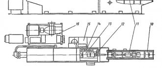
The general view and layout of the machine is shown in Fig. 32.
The main components of the machine are: bed 28, front stand 21, spindle head 22, table 10, rear stand 5 with steady rest 3, faceplate 13, radial support 14, cabinet 24 with electrical equipment, electric machine unit 25.
The parts to be processed are mounted on a rotary table 8.
The machining tool is placed either on mandrels fixed in the inner cone of the spindle 15, or on a tool holder mounted on the radial support 14. The tool intended for processing long holes is installed in long mandrels (boring bars), the right side of which is fixed in the inner cone of the spindle 15, and the left one rotates (and can simultaneously move in the axial direction) in the liners of the steady rest 3.
The machine spindle moves to a given coordinate using the following two adjustment movements:
- movement of the transverse slide 7 and the workpiece in the transverse (horizontal) direction. This displacement value is measured roughly (with an accuracy of 0.05 mm) using a ruler with a vernier 11 and more accurately (with an accuracy of 0.01 mm) using an optical screen 9;
- vertical movement of the spindle head 22 and the processing tool. This displacement value is measured roughly (with an accuracy of 0.05 mm) using a ruler 18 and a vernier 17 and accurately (with an accuracy of 0.01 mm) using an optical screen 16.
When working on horizontal boring machines, the following types of feeds are used:
- for processing cylindrical holes - axial feed of the spindle, and sometimes longitudinal feed of the table;
- for milling the end surfaces of parts - by transverse feed of the table or vertical feed of the spindle head;
- for processing the end surfaces of parts with a cutter, turning grooves or boring chambers in holes - by radial feed of the caliper;
- for cutting threads with a cutter - the axial feed of the spindle is equal to the pitch of the thread being cut.
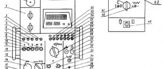
Location of controls for horizontal boring machine 2620, 2620A
List of controls for horizontal boring machine 2620, 2620A
- Start, reverse and stop spindle rotation
- Spindle jog
- Single-handle selective gear shifting
- Turning the faceplate on and off
- Starting and stopping the electrical unit
- Start and stop feed
- Selecting the feed amount with an electric variator
- Starting fast movements
- Starting installation movements
- Installation for transverse movement of the table and vertical movement of the spindle head
- Installation for longitudinal movement of the table
- Moving the spindle head by hand
- Longitudinal movement of the table by hand
- Lateral movement of the table by hand
- Installation rotation of the table by hand
- Adjusting the position of the steady rest
- Moving the rear pillar by hand
- Moving the spindle by hand and setting the spindle to feed
- Moving the faceplate radial support by hand and setting it to feed
- Quick installation rotation of the table
- Spindle clamp
- Faceplate Radial Caliper Clamp
- Headstock Clamp
- Table cross sled clamp
- Table sled clamp
- Turntable Clamp
- Rear pillar clamp
- Steady rest clamp
- Steady Rest Bushing Clamp
- Portable remote control. Duplicates movements 121; 122; 126; 128; 129
Kinematic diagram of horizontal boring machine 2620, 2620A, 2622, 2622A
Kinematic chain of the main movement drive. Since the cutting tool can be mounted on mandrels that are mounted in the spindle cone, and on the faceplate support, rotation can be imparted to both the spindle and the faceplate. In both cases, the two-speed electric motor M1, controlled from the remote control 11, through a kinematic chain with two three-crown blocks B1 and B2 rotates shaft IV with 18 frequency steps.
Spindle rotation VI. From shaft IV, through a two-stage gear transmission switched by coupling Mf1, rotation is transmitted to shaft V and spindle VI. The spindle VI can move axially inside the hollow shaft V.
Design and operating characteristics of the main components of the machine
The bed 28 (Fig. 32) is used to attach the machine to the foundation and to move the table 10 and the rear rack 5 along its guides. The bed has a box-shaped cross-section with internal stiffeners. A flanged DC electric motor is mounted on the right side of the frame to carry out feeds and accelerated idle runs of the working parts of the machine.
The front post 21 is rigidly fixed on the right extended side of the frame. The front post has vertical guides for moving the spindle head 22,
The mass of the spindle head is balanced by a load connected to it by a cable thrown over two blocks.
The spindle headstock 22 has the shape of a closed box, to which the following components are attached and located: the electric motor of the main movement drive, the gearbox, the spindle block, the tail part 23 of the spindle headstock, the faceplate 13 with a radial support 14, handles and machine control mechanisms.
The boring spindle is clamped against axial movements by handle 26, and the spindle headstock by handle 27.
The table 10 of the machine is used to install and move the workpiece and consists of three main parts: a longitudinal slide 6, a transverse slide 7 and a rotary table 8.
The longitudinal slide 6 can move along the guides of the frame 28 in the longitudinal direction or be rigidly fixed to these guides by a clamping device. To accurately measure the longitudinal movements of the table, use a ruler and vernier 29, which allows you to measure movements with an accuracy of 0.05 mm.
The transverse slide 7 can move along the guides of the longitudinal slide in the transverse direction or be rigidly fixed to these guides.
The transverse slide is moved by manually rotating the shank 31. The counting is carried out along a dial with a division value of 0.025 mm.
The rotary table 8 can be rotated along the ring guides of the transverse slide. On the surface of the table there are seven T-shaped slots for the heads of bolts that secure the workpieces. The middle groove is made calibrated in width in order to use stops to adjust the exact rotation of the table by 90, 180, 270 and 360°. Intermediate table positions are set with an accuracy of 0.5° on a circular scale.
After turning, the top of the table is clamped in the desired position.
The rear stand 5 with steady rest 3 serves to support the left end of the boring bars. The right end of the boring bars is inserted into the cone of the boring spindle 15. The rear stand can be moved along the frame guides 28 by rotating the square shank 1 with a removable handle. The rear stand is rigidly fixed in the desired position on the bed guides.
The steady rest 3 can move along the vertical guides of the rear pillar. The steady rest moves up or down simultaneously with the movement of the spindle head 22.
To ensure precise alignment of the steady rest bearing and the machine spindle, you can use an adjustment device, which is driven by flywheel 2.
To measure the vertical position of the steady rest axis, the rear post has a ruler with a vernier 4, which allows the reading to be carried out with an accuracy of 0.05 mm.
The steady rest has a hinged part that makes it easy to replace the hardened steel bushings. The inner diameter of these bushings is selected according to the outer diameter of the boring bar being installed. The hinged part clamps the bushings.
The faceplate 13 communicates the cutting movement to the tools mounted on the radial support 14.
Radial support 14 is designed for installing cutters operating with transverse feed for turning end surfaces on workpieces. The caliper rotates together with the faceplate and at the same time can perform radial feed.
Cabinet 24 houses the electrical equipment of the machine. The electric machine unit 25 is designed to generate the direct current necessary to power the electric motor. The unit consists of a three-phase alternating current electric motor driving a direct current generator.
The remote control 12 is used to control all the electric motors of the machine, except for the table rotation electric motor, which is controlled by the station buttons 30. The machine has a portable remote control 32 with the same buttons as on the remote control 12.
Operating rules
When working on a horizontal milling machine, you must comply with the safety regulations and regulations. Machine operators neglect these rules, and this poses a great danger to others and the performance of the equipment.
In order for the machine to serve for a long time and properly, you need to study its maximum characteristics. In no case should they be exceeded, as this can lead not only to damage to the equipment, but also to injury to the operator. A broken tool due to violation of cutting conditions can cripple the person working on it. It is prohibited to work on the machine without personal protective equipment and protective screens.
Design of radial drilling machines
Each radial drilling group machine consists of:
- hard base,
- cylindrical columns (internal and external),
- traverses (trunk),
- drill head (spindle head),
- electrical and hydraulic control equipment.
Main components 1 Base 2 pedestal 3 hydraulic pump motor 4 column 5 arm lifting/lowering tank and column clamp 6 spindle motor 7 arm lifting/lowering motor 8 arm lifting/lowering screw 9 Spindle head 10 arm
Kinematics
The main movements during drilling operations are the rotation and movement of the machine spindle quill. The kinematic chains that perform these movements are equipped with controls that allow the tool to be set to the required rotation speed and feed.
- rotation of the movable column of a radial drilling machine,
- vertical movement of the console (traverse),
- fixing the traverse on the column at operating height,
- fixing the spindle head on the traverse,
- switching spindle speeds and quill feeds.
When processing parts on radial drilling machines, the coordinates of the center of the hole and the axis of the tool are combined by moving the drilling head relative to the stationary workpiece in the polar coordinate system. This system is characterized by two parameters: the angle of rotation of the traverse and the radius of the position of the spindle head on it.
Machining holes at an angle is only possible when the workpiece itself is installed at an angle using special equipment and devices.
Radial drilling machine Z30132
Stand with work table
The machine bed, combined with the working base (table), is usually cast from gray cast iron. It is designed to fix the entire machine on the foundation, install the column base with the traverse and the spindle head, as well as fasten the equipment and parts using the T-shaped grooves of the working base.
A workpiece of small dimensions can be installed on an attached box-shaped table, or directly fixed on a specially treated surface of the base (work table). Fastening the workpiece outside the working surface of the table is rarely used, because introduces an additional error into the processing accuracy of the product.
Rotary column
The column is mounted vertically on the machine bed and rotates around its axis relative to a fixed internal stand on roller bearings. The traverse is fixed to the column.
A mechanism for raising/lowering the traverse, driven by an electric motor, is mounted in the upper part of the column.
Traverse (console)
The console (arm or trunk) of the radial drilling machine is mounted directly on the column; it has a separate electric drive, moves up and down, and also rotates around a vertical axis together with the support column. Rotation, depending on the machine model, can occur either manually or using an electric drive.
A drill head with a working spindle is installed on the guides of the cantilever traverse. The traverse can be lowered or raised according to the height of the workpiece. Electrical equipment and hydraulic elements are mounted in a niche located on the reverse side of the sleeve.
Spindle head
The drill head (spindle head), mounted on a traverse, is structurally a separate power unit, having feed boxes, speed boxes, as well as mechanisms for setting the drilling depth.
In radial drilling machines, the spindle serves to fix the processing tool and transmit torque and linear feed to it.
The tool is inserted into the inner cone of the quill (Morse taper No. 4-6 or metric taper, depending on the model), and then coordinately oriented relative to the workpiece by rotating the console and moving the spindle head along it.
For operator convenience, all machine controls are located on the drilling head:
- multifunctional steering wheel for moving the spindle headstock and spindle quill;
- buttons for controlling the clamping/unclamping of units, turning on/off spindle rotation, emergency stop, turning on the work area lighting;
- handles for selecting rotation speed, spindle feed, direction of spindle rotation, switching between manual and automatic feed.
| Radial drilling machine z3050 |
The feed box is located between the spindle and the spindle motor; Rotation from the electric motor is transmitted through gears and friction couplings. The friction clutch allows you to quickly reverse when cutting threads, cut off the feed when the required drilling depth is reached, and protect the gearbox from overloads.
The head can move along the console guides manually. It is fixed in the desired position before performing the drilling operation using a special clamping mechanism controlled by a separate button.
Since the spindle is mounted in a retractable quill, it allows holes of varying depths to be drilled without moving the yoke.
Fixation of the rotary column, as well as clamping/unclamping of the spindle head on the traverse guides, occurs using hydraulic mechanisms controlled by remote control buttons.
Coolant system
The coolant tank and the pump unit for supplying coolant to the tool are also located in the technological cavities at the rear of the machine. The switch is located in the base of the column. The coolant drains back by gravity.
Machine passport 2620A
This operating manual “ Passport of the machine 2620A ” contains information necessary both for the maintenance personnel of this machine and for the employee directly involved in working on this machine. This manual is an electronic version in PDF format of the original paper version. This documentation contains the Passport and Manual (instructions) for the operation of the horizontal boring machine 2620A.
CONTENT
PURPOSE UNPACKING AND TRANSPORTATION INSTALLATION AND INSTALLATION
- Foundation
- Machine installation
- Machine installation
PREPARATION FOR INITIAL START-UP PASSPORT
- Passport details
- Machine mechanics
- Machine equipment
- Machine controls
- Machine kinematics
- DESCRIPTION
- General structure of the machine
- Design of machine components
- bed
- Headstock
- Table
- Rear pillar
- Electrical equipment on the machine
- Accessories
- Optical devices
- Electrical equipment
- Machine kinematics
DESCRIPTION
- Main movement chain
- Feed chain
- Machine control
- Rotation
- Moving the moving parts of the machine
- Clamps of moving parts of the machine
- Machine locks
LUBRICATION OPERATING INSTRUCTIONS
- Measuring the movements of the moving parts of the machine
- Optical devices
- Precise stop mechanism based on coordinates
- Operating principle of precision stop mechanisms
- Setting the precision stop indicator scale
- Setting up rods with stops
- Threading
ADJUSTMENT INSTRUCTIONS
- Adjusting the spindle bearings
- Hollow spindle (models 2620 and 2620A)
- Hollow spindle (models 2622 and 2622A)
- Faceplate spindle
- Boring spindle
- Adjusting the gap in the screw pair of the radial support movement drive (for machines models 2620 and 2620A)
- Adjusting the thrust ball bearings of the propeller support in the tail section
- Adjusting the central overload fuse
- Adjustment procedure
- Adjustment of clamping devices
- Headstock Clamp
- Turntable Clamp
- Adjusting the clamps
- Adjusting the table rotation angle reference device every 90°
REPAIR INSTRUCTIONS
- Machine repair
- Special instructions about possible errors during repairs
download the passport of the horizontal boring machine 2620A in good quality from the link below.
Technological equipment for machine-building industries
CNC DRILLING AND BORING MACHINES
We produce and sell electric drives ETU, EPU for DC motors, tel./email +38 050 4571330 / Purpose, classification and design features of CNC drilling and boring machines. These machines are designed...
Increased production efficiency
We produce and sell electric drives ETU, EPU for DC motors, tel./email +38 050 4571330 / The development of production is largely determined by the technical progress of mechanical engineering. The increase in the output of mechanical engineering products is carried out for...