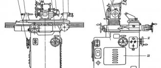
7B56 Location of components of a broaching machine
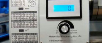
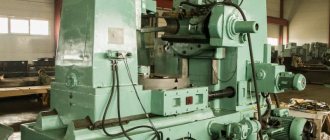
Photo of horizontal broaching machine 7B56
7B56 main components of a broaching machine
- electrical equipment
- slave cylinder
- work skids
- Remote Control
- cooling device
- support roller
- auxiliary cartridge
- auxiliary skid
- side stand
- locking and unlocking mechanism
- auxiliary cylinder
- working chuck
- work skids
- mechanism for regulating the movement of the machine
- coolant tank
- pumping unit
The main frame is used to accommodate the main parts of the machine: the working cylinder and the working slide, the alignment of which is ensured by bed strips welded inside the frame along its entire length. In the front part of the frame, the frame is closed by a massive base plate, in which a precise hole is made, strictly coaxial with the working cylinder of the machine. This hole is used to install the machine support plate. A slide is provided near the base plate, through which chips with coolant fall into a receiving box located next to the coolant tank. At the front of the main frame, there is a support roller mechanism at the bottom. Its purpose is to support the broach as its rear shank exits the auxiliary chuck. Support is provided until the end of the return stroke of the working slide, when the rear broach shank again enters the auxiliary chuck. The mechanism provides regulation using a spring device for working with broaches of different diameters.
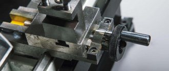
The working slide connects the working cylinder rod with the working chuck. To install the working chuck, they are provided with an adapter sleeve with a conical mounting hole. The design of the working slide allows the load to be transferred directly from the hydraulic cylinder rod to the working chuck using a special coupling and coupler (Fig. 68). The working slides of manufactured horizontal broaching machines move along one flat and one V-shaped bed guide, which increases the geometric accuracy of the machine. The slides are equipped with screwed guide bars that allow compensation for wear in the guides. There is a follower at the bottom of the slide to lower the support roller in the main bed when the work slide approaches the base plate.
The mechanism for regulating the movement of the machine is mounted in the upper part of the main frame. It is made in the form of two rollers, the angular rotation of which turns on and off the limit switches that control the operation of the machine’s hydraulic system. These switches are located outside the main frame in a special housing. By adjusting the position of the cams attached to the rollers, the required values of the working and slow strokes are ensured, as well as the value of the slow stroke and the extreme position of the working slide at the end of the return stroke. The rotation of the cams occurs under the influence of a copier mounted on the working slide.
The attached frame is designed for mounting mechanisms that provide supply and removal of broach. The inlet and outlet movements are communicated simultaneously to the support roller 6 (see Fig. 67) and the auxiliary slide 8 from the auxiliary cylinder 11. At the end of the broach supply, when the support roller is lowered into the opening of the attached frame, the locking and unlocking mechanism 10 ensures the release of the auxiliary slide from the mechanism inlet and outlet. This allows the auxiliary slide to accompany the broach until the end of the cut, which becomes possible due to the fact that the support roller 6 is recessed. At the end of the return stroke, the auxiliary slides are again rigidly connected to the inlet and outlet mechanism using a locking and unlocking mechanism. After this, the withdrawal of the broach begins, at the beginning of which the supporting roller rises and becomes the support of the broach. Its rear shank is fixed in an auxiliary chuck.
When broaching with assisted broaching, the machine mod. 7B56 operates in full half-cycle mode. The interaction of the considered machine mechanisms is reflected in Table. 21. When working in a simple half-cycle mode, the mechanisms located in the attached frame are excluded from operation. The sequence of actions is completely preserved. The simple half-cycle mode is usually used when working with small broaches, for example, keyway ones.
The adjustment dimensions that determine the capabilities of the machine in terms of the broaching length and the length at which tool tracking is provided are shown in Fig. 68.
General classification
The classification of metal-cutting machines is carried out according to various factors. These are divisions by weight, dimensions, type, accuracy class, degree of automation, and versatility. We need to talk about each of their groups in more detail.
Classification by type
There are 9 types of installations based on the type of equipment:
- Lathes. They occupy approximately 30% of the total mass of metal-cutting devices. The workpiece is clamped in a special clamp. The cutting process begins after installing the cutters, which remove a layer of metal under the influence of rotation.
- Boring, drilling units. They occupy 20% of the total mass of machines. The parts are fixed on the work table. Cutting occurs due to the rotation of the spindle with a drill clamped in the chuck.
- Grinding, grinding, polishing machines. They occupy 20% of the total mass of metal cutting installations. Metal cutting occurs due to the rotation of the abrasive material, which comes into contact with the working surface. The processing speed depends on the size of the abrasive.
- Devices for physical and chemical cutting of workpieces. Least common equipment.
- Devices for processing threads and teeth. Occupies 6% of the mass. Used for threading, manufacturing, and sharpening gears.
- Slotting, broaching, planing machines. They occupy 4% of the mass of metal-cutting equipment.
- Milling machines. They occupy 15% of the total mass. Processing of metal workpieces occurs due to the rotation of cutters of different shapes.
- Split installations. Used to separate reinforcement, profiles, corners.
- Machines for performing various operations related to cutting.
Classification by versatility
A separate division of metal-cutting machines is based on their versatility. There are two groups:
- Narrow profile installations. Used to perform one specific technological operation.
- Universal units. They are large-sized structures that are designed to perform various technological operations.
Classification by degree of accuracy
In terms of accuracy, metal-cutting machines come in several types, each of which has its own marking:
- Increased - denoted by the letter P.
- Normal - designation N.
- High - indicated by the letter B.
- Particularly high - designation A.
- The highest accuracy is indicated by the letter C.
To use units marked B, A, C, you need to prepare the room in advance. It must maintain a constant temperature and humidity level.
Classification by degree of automation
Based on the degree of automation, the following types of metal-cutting machines are distinguished:
- Manual models. The worker needs to clean, prepare workpieces, set up all moving elements independently, and coordinate the work process.
- Semi-automatic machines. The worker needs to change parts independently, turn on and off moving mechanisms.
- Automatic machines are units that process workpieces independently. Used in mass production.
- CNC equipment. The operator sets the required algorithm through the program. The moving mechanisms work independently, select optimal modes, load and unload parts.
CNC machines are gradually replacing other machines due to high processing accuracy and increased productivity.
Metal cutting automatic machine
Classification by weight
Industrial metal-cutting machines are divided by weight. Highlight:
- Lightweight - structures weigh up to 1000 kg.
- Medium - weight starts from 1 ton and ends at 10 tons.
- Large - weight from 16 to 30 tons.
- Heavy - weight from 30 to 100 tons.
- Super heavy - structures weigh more than 100 tons.
Designations are indicated in the technical data sheet.
7B55 Horizontal broaching machine for internal broaching. Purpose and scope
The horizontal broaching machine 7B55 has been produced since 1981. The machine was discontinued and was replaced with a more advanced model. Currently, the plant produces more advanced horizontal broaching machines and semi-automatic machines: 7A523, 7A534, 7A545, 7555.
The horizontal broaching machine 7B55 is designed for processing, by broaching, pre-processed or rough through holes of various geometric shapes and sizes of parts made of ferrous and non-ferrous metals and alloys. Using special devices, you can process external surfaces.
The 7B55 broaching machine is distinguished by high productivity and high processing accuracy.
The most effective use of the 7B55 machine is in mass and large-scale production. The ease of readjustment of the machine allows it to be used in small-scale and individual production.
Design features of the horizontal broaching machine 7B55:
By agreement with the customer, the machine is supplied both in a universal version and with special fixtures and tools for processing one or more specific parts.
When equipped with automated devices for feeding and removing workpieces, the machine can operate in an automatic cycle, as well as be built into automatic lines.
The machine drive is hydraulic, the speed control of the working and reverse strokes is stepless.
The removal and supply of the broach to the working chuck, as well as the cutting process, are mechanized.
For ease of maintenance, the machine is equipped with a mechanism for adjusting the stroke length of the working slide, centralized forced lubrication of the guides, signaling of dullness of the broach using an electric contact pressure gauge, and oil filtration in the hydraulic system.
Starting and safety electrical equipment is located in a separate electrical cabinet, which facilitates its maintenance and increases its service life.
The use of contactless track switches, low-current electrical control equipment and electrical control equipment and DC electromagnets ensures high reliability of electrical equipment.
The increased rigidity and vibration resistance of the machine design allows it to work in the entire range of operating speeds and traction forces, while maintaining a high class of surface cleanliness and broaching resistance.
- Hydraulic drive
- Stepless speed control of working and reverse strokes
- Mechanized feed in and out of the broach over the entire cutting length
- Centralized forced lubrication of rubbing surfaces
- Hydraulic oil filtration
- Signaling using an electric contact pressure gauge about the dullness of the cutting tool
- High reliability of electrical equipment due to the use of contactless track switches, low-current electrical control equipment and DC electromagnets
- Possibility of integrating the machine into an automatic line
On special order for an additional fee, the machine is equipped with a supporting prism, which allows you to compensate for the weight of the workpiece and simplify the process of its installation relative to the broaching axis, and a load lifter for installing and removing heavy workpieces and broaches.
At the request of the customer, the machine can be manufactured in one of two versions: with or without an attached bed (model 7B55U), and can also be supplied both in a universal version and with a special device and tool for processing one or more specific parts.
The machine is certified according to the first quality category.
Roughness of processed surfaces Rz20—Ra 0.63 μm (V5—V8).
Machine accuracy class N according to GOST 8-77.
The corrected sound power level LpA does not exceed 108 dBA.
Design organization - Minsk Special Design Moscow Bureau of Broaching Machines.
Main technical characteristics of the horizontal broaching machine 7B55
Design organization - Minsk Special Design Moscow Bureau of Broaching Machines.
Minsk Machine Tool Plant named after S.M. Kirov. Start of mass production in 1973.
- Nominal traction force – 98 kN (10,000 kgf)
- The longest working stroke of the slide is 1600 mm
- The diameter of the hole in the faceplate is 100 mm
- Working speed – 1.5÷11.5 m/min
- Main movement drive electric motor power – 17 kW
- Machine weight – 6.9 t
Review of the metalworking machine model 7B56
Since 1981, a broaching machine model 7B56 began to be produced for the industrial area. They are processed on a broaching machine of this model using the method of correct horizontal broaching through the through holes of the part. The processing itself is rough, and the composition of the processed parts is ferrous and non-ferrous metals, as well as various alloys.
If additional tools were used, it became possible to carry out external processing of parts. This device had high processing accuracy and sufficiently high productivity to be used on an industrial scale. Below is a description of the design features and characteristics of the broaching horizontal machine 7B56.
Its features include:
- smooth adjustment of the speed of both working and return movement;
- hydraulic drive of the existing broaching mechanism;
- good quality of the machined surface, associated with increased resistance of the machine to vibrations. This condition was achieved due to an increased level of rigidity and allows for uniform operation over the entire range of traction forces at any speed;
- automatic supply of lubricant to all rubbing surfaces, as well as high-quality filtration of oil in the hydraulic system;
- triggering of the existing alarm when the cutting tool becomes dull;
- the presence of contactless track switches, as well as DC electromagnets, makes it possible to achieve a high degree of reliability and safety of all electrical equipment;
- the possibility of upgrading this machine for subsequent installation on an automatic line;
- the processing accuracy of the horizontal broaching machine 7B56 belongs to the normal class (H);
- the total length of the working stroke of the existing horizontal slide is 160 cm;
- the speed of movement of the broaching mechanism varies in the range of 1.5 – 11.5 meters per minute;
- hydraulic traction force is 200 kN;
- the presence of a powerful 30 kilowatt electric motor that drives the main drive.
Hydraulic diagram of broaching machine 7B56
Vertical broach
The operating principle of a vertical broaching machine for internal broaching is based on the fact that the main movement is carried out rectilinearly in the vertical direction by the cutting element of the machine while the workpiece of the future part remains stationary. In addition, when using the screw broaching method on such devices, which is one of the types of internal broaching, additional rotation is also imparted to both the workpiece itself and the cutting element.
Vertical broaching machine
A vertical internal broaching machine has almost the same operating principle as a horizontal one, but with some advantages, which include the following:
- during operation, machines of this class completely eliminate the possibility of sagging and bending of the axis of the broaching element;
- On a machine of this class, it is not difficult to install additional broaches in case of modernization;
- A vertical broaching machine occupies a relatively small working area. This is due to the fact that its entire working cycle occurs strictly in the vertical direction.
- Machines with vertical broaching not only take up less usable space during operation, but are also more convenient than their horizontal “brothers”. These machines are quite often used in production, where mass processing of light and medium-heavy parts is carried out.
Scheme for setting up a vertical broaching machine
Vertical broaching machines also come in both external and internal broaching types. All these types have the following characteristics:
- traction force, depending on the machine model, can range from 50 to 200 kN;
- the maximum maximum amount by which the working carriage moves is in the range from 60 to 160 centimeters;
- the broaching speed during the working cycle can vary from 0.5 to 14 meters per minute.
It is worth noting that both horizontal and vertical broaching machines use a semi-automatic operating principle in their process. The only exception is CNC broaching machines, the entire production process of which is simplified as much as possible and has the highest speed.
Another feature that distinguishes metalworking machines from each other is the number of working carriages available, since there are machines not only with one, but also with several. The next distinguishing feature is position. The simplest is a single-position design, but the most effective are considered to be machines with a multi-position operating principle, since they contain factory-made table devices with a rotary system in their technological equipment.
Elements and geometry of the cutting part of the broaches
The round broach (Fig. 21) consists of the following elements. Locking part 1 (shank) serves to secure the broach in the chuck of the machine's traction device; neck 2 – connecting surface. The guide cone 3 and the front guide part 4 serve to center the workpiece at the beginning of cutting. The cutting part 5 consists of cutting teeth, the height or width of which increases by the height of the layer being cut, and serves to cut off the main portion of the allowance. To facilitate the formation of chips on the cutting teeth, chip-breaking grooves are made in a checkerboard pattern.
The calibrating part 6 is designed to give the treated surface the final shape, the required accuracy and roughness. It consists of calibrating teeth, the shape and dimensions of which correspond to the shape and dimensions of the machined surface. The rear guide part 7 is necessary to support the broach as it exits the machined hole. Rough and finishing teeth of broaches have different geometries.
The rough teeth (Fig. 21, a, section A–A) are sharpened. The clearance angle for internal broaches is 3°, for external broaches – 3–8º. The rake angle is selected depending on the properties of the material being processed within 10–20°. The pitch between the teeth is selected from the requirement that at least three teeth operate simultaneously. Lift per tooth – 0.06–0.3 mm/tooth.
A
b c
Rice. 21. Broaches: a, b – round; 1 – locking part; 2 – neck; 3 – guide cone; 4, 7 – front and rear guide parts, respectively; 5 – cutting part (cutting teeth); 6 – calibrating part (calibrating or finishing teeth); f – ribbon; Sz – rise per tooth; t – pitch between teeth; α, γ – main rear and front angles, respectively; c – broach for making an internal keyway
Finishing teeth (Fig. 21, a, section B–B) are made with a strip equal to 0.02–0.3 mm. The rake angle is selected depending on the properties of the material being processed within the range of 0–15°. A zero rake angle is usually assigned for profile broaches, which makes it possible not to lose the geometric accuracy of the teeth during regrinding. The pitch between the teeth t is selected from the requirement that only one tooth participate in the work. Lift per tooth – 0.015–0.03 mm/tooth.
Specifications
One of the disadvantages of such machines is the dimensions. As a rule, this is an elongated platform in which the workpiece is placed. Dimensional characteristics on average are about 2 m in length, 0.5 m in width and 1.5 m in height. However, the configurations can be different - accordingly, the sizes also differ. The weight is about 500 kg, so before installation it would be a good idea to provide a reliable foundation. From a productivity point of view, the speed of drawing, that is, processing, is also important. For example, a broaching machine from the Flexible Connections enterprise in modification SGP.12.35 provides a working speed of 220 mm/min. In other words, in one minute the equipment can make a cut on an internal surface more than 20 cm long. Here it is also worth considering the maximum processing area, since in most cases, performing the same cutting lines in two approaches is technologically unacceptable. The average length of a single service varies from 4 to 5 m.
Design and principle of operation
The mechanical part of planing machines consists of the following elements:
- cast iron or steel frame - the main part of the structure that bears the main loads, used to accommodate the assembly with the cutting tool and the work table;
- working surface - designed for placing workpieces and fastening them;
- guides—necessary for moving the slider or working surface;
- slider - performs translational movements when processing workpieces;
- a cutter used for cutting metal;
- caliper - fixes the cutter at a certain angle;
- gearbox - used to change the rotation speed of the spindle with a fixed workpiece;
- vice for fixing parts during processing.
The design also includes electrical components: motor, controls, monitoring sensors, protection systems. To cool the mechanical elements, a system for supplying lubricants and coolants is used. All machine components are located inside a steel or cast iron body.
The operating principle is based on direct contact of the cutting tool with the workpiece. Machining occurs when the workpiece moves or rotates relative to the cutter.
Processing the part (Photo: Instagram / khuevgen)
Radial drilling machine 2L53
- Radial Drilling Machine Controls
- The device of a radial drilling machine
- Kinematic diagram of a radial drilling machine
- Electrical diagram of a radial drilling machine
- Drill head of radial drilling machine
- Feed activation mechanism
- Technical characteristics of this radial drilling machine
The 2l53 radial drilling machine is designed to perform drilling operations with a maximum drilling diameter of 35 mm. In addition, the machine can perform other operations, such as drilling, countersinking, and reaming.
The machine is equipped with accessories and special tools, which allows you to expand the scope of application and increase labor productivity.
Controls of radial drilling machine 2L53
- Manual table rotation;
- Column barrel clamp;
- Turntable clamp nuts;
- Sleeve clamp on column;
- Electric push-button station;
- Speed dial;
- Gear shift knob;
- Feed shift knob;
- Moving the drilling head along the sleeve;
- Feed switch handle;
- Feed mechanism dial clamp;
- Drill head clamp on sleeve;
- Fine manual spindle feed;
- Rotate the spindle head;
- Feed set handle;
- Drill head clamp
Design of a radial drilling machine 2L53
The radial drilling machine 2l53 consists of the following components:
- Sleeve and plate;
- Barrel;
- Drill head;
- Feed activation mechanism;
- Sled;
- Rotary table;
- Cooling system;
- Threading head;
- Electrical equipment that requires a private electrician to install
Kinematic diagram of the radial drilling machine 2L53
Electrical diagram of the radial drilling machine 2L53
Drilling head of radial drilling machine 2L53
The drill head of a radial drilling machine is made of cast iron, into which the gearbox and feed box are mounted.
The gearbox provides the spindle with eight speeds. Through bevel gear 1, shaft 2 receives torque from horizontal shaft 1. Gears 3, 5 and 7 transmit torque to shaft 3. Shaft 3 will receive different torque depending on which of the pairs of gears 2 and 3, 4 and 5 or 6 and 7 will be engaged. On shaft 3 there is a movable block that enables the inclusion of wheels 8 and 9, 10 and 11 or 11 and 12, which makes it possible to obtain eight speeds on the spindles with a range from 35.5...1400 rpm.
Shaft 5 of the feed box receives rotation through gears 16 and 19. When gears 18 and 24 and 25, 29 and 30 are turned on, torque is transmitted to shaft 7. The shaft receives three different speeds, depending on which of the pairs of gears 25 and 26, 27 and 29 or 28 and 30 will be engaged.
Switching the speeds of the feed box and gearbox is carried out using handles located in the drill head housing.
Feed activation mechanism
The feed switching mechanism is designed for mechanical and manual (accelerated) feed of the spindle and is located in the lower part of the drilling head.
Mechanical feed is carried out by turning handle 2 to the “pull” position, then the toothed fingers 3 engage with part 4 connected to the worm wheel 5.
Manual feed is carried out by handle 1 to the “pull” position.
For a stable drilling depth during manual feed, stop 1 is used.
Technical characteristics of the radial drilling machine 2L53
| Main settings | 2L53 |
| Largest drilling diameter, mm | 35 |
| Spindle offset: | |
| greatest | 1000 |
| least | 290 |
| Maximum distance from the bottom end of the spindle to the plate, mm | 1160 |
| Maximum spindle stroke, mm | 325 |
| Spindle taper | Morse 4 |
| Machine mechanics | |
| Number of spindle speeds | 8 |
| Speed limits, rpm | 35,5. 1400 |
| Number of innings | 6 |
| Feed limits, mm/rev | 0,1. 1,1 |
| Machine dimensions, mm: | |
| length | 2000 |
| width | 790 |
| height | 2390 |
| Machine weight, kg | 2300 |
The machine is equipped with accessories and special tools, which allows you to expand the scope of application and increase labor productivity.
Features of operation
Operating personnel are required to place the workpiece in the working niche of the equipment. Next, after launch, the actual processing process begins. A key feature of the functioning of such machines is the fact that the working elements in the form of broaches do not remove chips immediately after cutting, but push them out only after the final exit from the body of the workpiece. Therefore, the range of operator tasks is also expanded due to the need to monitor how correctly machining is performed. On vertical-type broaching machines, the risks of deviations and incorrect cut lines are not so high, since bending of a long workpiece due to its own weight is eliminated.
Part processing technology
The description of the processing process on broaching machines is as follows: the part to be processed is fixed to a standard work table faceplate in compliance with all safety measures. A broaching device is passed through the hole of this part, which is fixed directly in the traction chuck. After turning on the start button, oil is supplied into the inside of the cylinder, which presses on the rod, forcing the broaching element to move.
At the time when the moving carriage with its thrust element runs into a special stop for rearrangement, the limit switch is triggered, as a result of which the working stroke of the carriage is stopped. At the next stage of operation, its movement in the opposite direction will occur.
At the final stage, the operator activates the feed idle button, after which it will return to its original position and at this point the working cycle of the device will be considered completed.
Modern horizontal broaching machine
The options for fixing the broaching element in the chuck also depend directly on the model of the broaching machine, which can be not only conventional and quick-release, but also fully automatic.
Due to the fact that there is a special thread on the shank of the machine body, the chuck is connected to the working carriage.
Great Encyclopedia of Oil and Gas
| Multi-cutter attachment for a planer. |
Vertical-broaching machines, compared to horizontal-broaching machines, occupy a smaller area, are more convenient in securing broaches, but have a high workplace due to the need to place the broach under the working position. Vertical machines are used in mass production for processing light and medium-weight parts. The machines are produced for external and internal broaching. Their nominal traction force is 50 - 200 kN, working speed is 0 5 - 14 m / min, carriage stroke length is 600 - 1600 mm.
Vertical broaching machines occupy a significantly smaller area than horizontal ones. It is more convenient to install workpieces for processing on these machines; removal of the part can occur automatically; After broaching, there is no need to return the broach to its original position, since it is automatically secured either to the upper end or to the lower end.
| Horizontal broaching machine model 7510M. |
Vertical broaching machines are used mainly for external broaching.
| General view of a horizontal broaching mill. |
Vertical broaching machines are used mainly for external broaching. The operating principle of such machines is similar to horizontal broaching machines. To increase labor productivity in mass production, continuous broaching machines are widely used.
Vertical broaching machines for external broaching allow the following traction forces: mod.
Vertical broaching machines for internal broaching must be equipped with a guard that protects workers from injury if the broach falls out of the return mechanism chuck. The design of the fence must prevent hands from entering the area between the broach and the fence.
Vertical broaching machines for internal broaching must have a guard to protect workers from injury if the broach falls out of the return mechanism chuck.
According to the hydraulic drive scheme, vertical broaching machines differ little from horizontal broaching machines and have similar control units. All hydraulic drive calculations for reciprocating motion given in the planing machines section are generally applicable to broaching machines.
Machines used for broaching are divided into horizontal, vertical and continuous. Vertical broaching machines occupy a significantly smaller area than horizontal ones. It is more convenient to install workpieces for processing on these machines; removal of the workpiece can occur automatically; After broaching, there is no need to return the broach to its original position, since it is automatically secured either to the upper end or to the lower end. Vertical broaching machines are produced in one- and two-position versions; they can broach one or two workpieces at the same time.
When performing a broaching operation, the cutting speed is regulated by the kinematics of the broaching machines and the drive power of the broaching machines. Small vertical broaching machines have a tractive force of up to 100 kN and can reach cutting speeds of up to 25 m/min. In practice, the maximum service life of broaches is usually achieved at a cutting speed v 5 m/min. However, in order to increase productivity, the cutting speed can be increased to 10 m/min.
When performing a broaching operation, the cutting speed is regulated by the kinematic capabilities and drive power of broaching machines. Small vertical broaching machines have a tractive force of up to 100 kN and can reach cutting speeds of up to 25 m/min. In practice, the maximum service life of broaches is usually achieved at a cutting speed v 5 m/min. However, in order to increase productivity, the cutting speed can be increased to 10 m/min.
Pages: 1 2
Longitudinal planing and slotting machines
Universal two-column longitudinal planing machine mod. 7212 is designed for finishing surfaces and cutting long grooves of various profiles.
Technical specifications. The largest transverse dimensions: width - 1250 mm; height - 1120 mm; dimensions of the working surface of the table - 1120... 4000 mm; caliper feed: when moving along the crossbar - 0.5...25; for other movements - 0.25...12.5 mm/d. move. The main unit of the machine is the table on which the workpiece is fixed. The table moves back and forth relative to the fixed cutters installed in the supports. The table movement is the main cutting movement; the reverse motion of the table is auxiliary, carried out at high speed, and during the reverse motion the cutters rise. The supporting system of the machine consists of a bed, a stand and a connecting beam at the top.
Two calipers on the crossbar and one caliper on the stand make vertical and horizontal movements and are used for installation or are used for periodic feeding of cutters, as well as their deepening. The caliper can be rotated at an angle of 60°. A table drive is mounted next to the frame.
The main movement is the cutting movement, i.e. the movement of the table with the workpiece being processed is communicated from the M1 DC motor through a two-stage gearbox with an M1 gear coupling and a helical rack and pinion gear (Fig. 2). Maximum table movement speed vmax = (17/63) (26/49) 3.14 12 10 = 80 m/min. Technical characteristics of slotting machines are given in table. 2.
Table 2. Slotting machines
Rice. 2. Kinematic diagram of a two-column longitudinal planing machine : a - crossbar clamping mechanism; b - table; c — control panel
Models of broaching machines differ in several ways:
- purpose - internal or external broaching;
- universality - general and highly specialized purpose;
- direction of working movement - horizontal or vertical;
- the nature of the working movement - circular, broaching movement, workpiece movement;
- number of carriages - one or several;
- position - conventional machines (single-position), with rotary tables (multi-position);
- availability of CNC.
Safety requirements
When working on broaching machines, it is necessary to strictly observe personal safety measures, which have general principles for all metalworking equipment.
There is a specialized document containing a set of conditions and requirements for broaching machines installed in production. So, for example, safety when cutting on metalworking machines with vertical broaching is ensured by installing a special protective element that protects the operator from injury in cases where the heavy broaching mechanism falls out of the chuck.
During the period of work on horizontal broaching machines, it is mandatory to install a protective folding screen with glass to monitor the process throughout the entire exit area of the broaching element.
It is worth noting that for safety reasons, it is strictly forbidden to install or remove the broach while the metalworking machine is operating. In the case of using a broach whose weight is more than eight kilograms, the use of a special lift is a mandatory requirement.
Horizontal broach
A horizontal broaching machine is used in all cases when there is a need to process the internal or external part of a part, the main movement of which will occur in the linear horizontal direction. Correct movement is achieved through special broaches having different profiles.
Horizontal broaching machine
The working cycle of such a machine is carried out only in a strictly horizontal direction. Removal of chips from the entire area of the workpiece during operation is carried out due to the uniform movement of the teeth over the entire length of the existing broach. In order for the entire process to be fully automated and safe, it makes sense to use a machine for processing and cutting metal with a CNC installed.
Machines with vertical broaching are designed for precision machining of the surfaces of parts of various shapes, made of both ferrous and non-ferrous metals. A vertical broaching machine is used, as a rule, in various industries - such as mechanical engineering - for the purpose of mass production of parts of all possible shapes.
Scheme for setting up a horizontal broaching machine