CNC machines are computerized machines with numerical control that can perform a specific set of operations in accordance with the program embedded in them. Such machines can be controlled using computers (the most complex machines) or microcontrollers. CNC machines usually have both stepper and servo motors. CNC machines also include plotters that can draw any objects according to a given program.
In this project we will look at creating a DIY (DIY) CNC plotter using an Arduino Uno board. Of all the plotters you can make yourself, this is one of the simplest. Our homemade plotter will be able to draw most basic shapes, texts and even cartoons. It works on approximately the same principle as the human hand, but much faster and more accurately than a human can draw. You can watch the detailed operation of this plotter in the video at the end of the article.
CNC plotter operation
To operate a CNC plotter, CNC plotting requires 3 axes (x-axis, y-axis and z-axis). The x and y axes work in unison to create a 2D image on plain paper. These axes (x and y) are located at 90 degrees to each other such that any point on a flat surface is defined by a given x and y value. The z axis is used to raise and lower the pen onto flat paper.
Depending on what image needs to be drawn, the computer will generate the corresponding coordinates and send them to the microcontroller via the USB port. The microcontroller interprets these coordinates and then controls the position of the motors to create the image. We used an Arduino board as the microcontroller in this project.
Required Equipment
- Arduino - As we already said, we will need an Arduino to install GRBL. Specifically, we need an Atmega 328 based Arduino board, which means we can use either an Arduino UNO or a Nano.
- Stepper motors. Obviously, stepper motors provide the movement of the machine.
- Drivers – To control stepper motors we need drivers, and a common choice when it comes to small DIY CNC machines (using NEMA 14 or 17 stepper motors) is the A4988 or DRV8825 drivers.
- Arduino CNC Shield - To connect stepper drivers to Arduino, the easiest way is to use Arduino CNC Shield. It uses all the Arduino pins and provides an easy way to connect everything, stepper motors, spindle/laser, limit switches, cooling fan, etc.
Please note that these are only the basic electronic components that we need to understand how a CNC machine works.
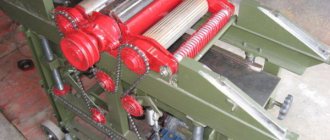
As an example of how everything should be connected, we can take a look at one of the DIY CNC foam cutting machines.
GRBL CNC machine assembly diagram
Here you can check and get the main electronic components needed to assemble this CNC machine:
- Stepper Motor - NEMA 17
- Stepper driver A4988
- Arduino CNC Shield
- Arduino Uno
The main tool of this CNC machine is the hot wire, which can easily melt or cut through the polystyrene foam into any shape we want.
Required Components
Hardware components
- Arduino Uno board (buy on AliExpress).
- Shield (expansion board) for L293D motor driver (buy on AliExpress).
- Old HP/Epson printer. You can use an old computer DVD drive.
- Mini servomotor (buy on AliExpress).
- Aluminum sheet (710mm x 710mm).
- Organic glass.
- Bolts and nuts.
- Pen.
Note : The mechanical parts of this project may differ in many ways from what you see in the photos in this article. But whatever “mechanics” you use, make sure that it has a servomotor. For example, we couldn't find an old DVD drive, so we used parts from an old printer to build our plotter.
Tools
Screwdriver Drill Cutting tool (hacksaw) Glue Bench device
Software
Arduino IDE version 1.6.6 or later Processing IDE version 3.1.1 or later (the latest version can be downloaded here) Inkscape version 0.48.5 or later. (download here) Grbl controller (optional)
What is Arduino
First of all, it’s worth understanding what Arduino is.
- the name of the brand of equipment, programming tools with the help of which it is possible to build models of machine tools (including three-axis ones), simple automation and robotics systems;
- a product line whose open architecture will allow you to copy or complement existing designs;
- a small board with its own processor and memory;
- hardware computing platform or controller;
- a programming language that allows you to disassemble various software (shareware, the latest news in the field of IT);
- so-called electronic designer.
By creating electronic devices on Arduino that are capable of receiving signals from various digital and analog sensors connected to it as a base. Therefore, in the context of this article, we will talk about boards.
Base for CNC plotter
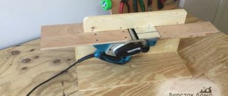
The base of our plotter is the base to which all structural elements are attached to make the device rigid and at the same time portable. For the base of our plotter, we used an aluminum sheet because it is light, durable, easy to bend and cut, and it does not rust (in case your grandchildren will draw on this plotter in many, many years).
The design and dimensions of the base are shown in the following figure (all dimensions are in mm):
After carrying out the necessary bending and cutting operations, we ended up with the following design:
Advantages of using Arduino when creating CNC machines with your own hands?
Main advantages:
- low fee;
- The programming environment is simple and convenient, suitable for beginners;
- cross-platform.
You can make your own CNC machine. This will save quite a lot of money, but it won’t be possible to do it completely free, since some parts cannot be made at home. But compared to factory models, the savings are so great that it's worth your time.
- 06 September 2020
- 7962
Assembly of X, Y and Z axes
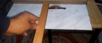
To assemble the x and y axes, we used two supports (cradles) from the printer. Each of these parts contains a stepper motor, and a belt drive mechanism is used to move the cartridge in forward and reverse directions.
For the z-axis we used a mini servo motor which we attached to the y-axis with glue. This servomotor will be used to raise and lower the pen (pencil). It is also necessary to design a good support mechanism that would allow the handle to be raised and lowered freely.
Assembling a budget CNC field A4 on Arduino+RAMPS
Assembling a budget CNC field A4 on Arduino+RAMPS
Ovaday » January 31, 2015, 08:48 pm
LCD Nokia 5110. 200 x 1 = 200 Switch SPDT MTS -102 . 30 x 3 = 90
KY-026 IR Flame sensor module. 150 x 1 = 150 KY-008 Laser head sensor module. 140 x 1 = 140 Arduino Starter Kit. 380 x 1 = 380 10pcs 20cm jump wires 1f1f . 40 x 1 = 40 Arduino Mega 2560 R3. 960 x 1 = 960 RAMPS 1.4. 640 x 1 = 640 Stepper Motor Driver DRV8825. 240 x 3 = 720 Flexible Coupler 5x8x25mm. 140 x 3 = 420 Ball Bearings 608ZZ. 30 x 2 = 60 Sum. 3800 Discounted amount. 3610 + delivery by postal parcel 1st class. . 270 Total. 3880
Plotter diagram
Insert the L293D motor driver shield into the Arduino board. This expansion board can simultaneously control two stepper motors and two servo motors. Attach two stepper motors to it as shown in the figure. The ground connections must be left unconnected since we have bipolar motors.
Also connect the mini servo motor to the servo1 connector. Apply 7.5V - 9V power to the power port of the motor driver shield. The device is ready for testing.
What are shields for?
The use of shields allows you to significantly expand the functionality of the router. Most often they are made to fit the board form factor. You can use several shields at the same time. The range of applications is very wide:
- Ensuring independent operation from a computer.
- Connecting peripheral devices.
- Output information to peripheral devices directly from Arduino.
- Simultaneous control of a large number of motors.
- Storage and processing of voluminous information.
- Connect to Wi-Fi.
- Connecting mobile network antennas.
- Playing music on Arduino, etc.
IMPORTANT . When connecting shields, you must be careful not to damage the Arduino board.
How to Generate Your Own G-Code
In this section of the article we will look at how to generate G-code for the inscription HELLO WORLD using Inkscape software.
Note : Inkscape cannot save G-codes. Therefore, additionally install this MakerBot Unicorn plugin which allows you to export images to G-codes. But newer versions of Inkscape may already be able to save G-codes. The original of this article was written in 2022, perhaps something has changed since then.
If the installation was successful, open the File menu in Inkscape and click on “Document Properties”. First change the dimensions from px to millimeters (mm). Also reduce the width and height to 90mm. Now close this window. After this, a square will appear in the drawing area - it is in it that we will write our text.
Now on the left in the toolbar, click on “create and edit text object tab”. Write the text “HELLO WORLD” and set it to the required position using the tool shown in the following image.
Click text and select the font you need. Click apply and close.
Now click on “path” and select “object to path”. Your text is now ready to be saved as G-code. Click on file -> save and write the file name “hello world”.
Change the file type to “MakerBot Unicon G-Code” as shown in the following image (this option will be available to you if you have successfully installed the MakerBot Unicorn plugin). Now click on “save” and click on “ok” in the window that opens.
You can use the saved G-code to draw on a plotter using the operations described above.
Projects / Modifications
Why does the drawing “crawl” over the edge of the table or is it too small?
Quite often you see how beginners and not so CNC operators try to calculate the scale of the product at the development stage of the machine. They recalculate the degrees of rotation of the motor, the pitch of the ball screw, the length of the run and a lot of other parameters. Meanwhile, there is a simple method to achieve true scale on the machine without such labor-intensive procedures. With this article I will try to help all CNC machine enthusiasts.
We assume that you have already decided what engine power suits you.
So, install the existing motors on the machine axis
Install any ball screw that you were able to buy or get.
If there is no ball screw, then install any trapezoid screw
The pitch of the screw thread and the angle of rotation of the motor do not matter!
So your machine is ready, connected to the computer, the CNC program is running (in our case it is MASN-3)
Fig1 axis motor settings window
Open the Notepad program - (Start-all programs-accessories-notepad)
Read also: How to convert an AC ammeter into a DC one
Type in the program
Save the program under any name with the extension “txt”
Save to “Desktop” for quick search
Load the program into MASN-3 (File-Open Gcodes).
Touch it to the workpiece with a slight recess
Reset all coordinates
Run the program you wrote.
The machine will draw a segment 50mm long
Measure the resulting size of the segment and divide the resulting number by the number in the MASN-3 program window along the path -> “Shaged units” in the window at the address “Configurations” then “Configuring engines”
(The first window from the bottom left is labeled “”)
number of steps per 1 mm of machine movement
Divide this number by 50 (the length of your segment) and enter the resulting number
Mill the section again and check the result, repeat the settings if necessary.
Example
We created a “segment” file whose length was set to 50 mm.
Uploaded to MASN-3
We obtained a cut size on the machine equal to 55 mm.
We need to bring it to 50 cm (since we set it initially)
Open “Configurations” then “Engine settings” in the “Stage units” window we see a number for example 2000
Where 2000 is the available number in the “Shaged units” column.
55 - the result obtained on the machine (in mm).
36.36 = 1 machine pitch (1mm)
1818 = 50 machine steps (50mm)
1818 - We enter this number in place 2000 in the table
Precise fit
We drew a “segment” file on the machine after the adjustments made above.
1818 50,5 = 39,60
39.60 x 50 = 1980—Enter this number into the table
That's all. Good luck!
GRBL controller
Once you have generated G-code using Inkscape, you may need to check whether it fits within the given constraints (if drawable).
Drawing restrictions are defined in the following lines of code in our Arduino program:
In the next window of the GRBL controller, you can check whether the image on the G-code we generated goes beyond the drawing limits specified in the Arduino program. If any part of the image exceeds these limits, it will not be drawn.
In our example, the x and y values range from 0 to 40 mm. But since we designed a plotter with a larger drawing area, we changed the maximum limit from 40 to 60 mm.
Therefore, after you have drawn G-code in Inkscape, it is advisable to check it using the GRBL program before loading it into the Arduino board to see if it goes beyond the drawing area. If it doesn't, just resize it in Inkscape.
How to make a CNC machine for burning on various materials?
The burning machine works using a laser, which focuses a beam on the surface of the material. Typically the focal length is no more than 0.001 inches.
The principle of manufacturing and firmware is the same as when creating a router. Only instead of a milling cutter they use a laser with a power of 5.5 watts or more.
When properly configured, the operating speed of the laser burning machine is 10 meters per minute. It can be increased if you control the device from a laptop by removing the LPT cable.