The grinding machine is very common and in demand among the tooling available in the workshop, so its manufacture will be practical and justified. With its help, you can process not only wooden blanks, but also some types of other materials, such as plastics and some metal blanks, of course, without fanaticism (no grinder!). In this article we will describe the process of creating such a machine.
How to make a belt sander
Many home craftsmen and professionals are wondering how to make a grinding machine with their own hands.
The reason for this question is quite simple: the high cost of serial grinding equipment, which not everyone can pay off if not used regularly. In order to make such equipment, you will need several main components: an electric motor, rollers and a reliable frame. Naturally, drawings of such a device or a photo of it would not be superfluous. Also at the end of the article you can watch videos on assembling a tape machine on your own. The motor for belt grinding equipment is not difficult to find; it can be removed from an old washing machine. You will have to make the frame yourself; for this you can use a sheet of metal with dimensions 500x180x20 mm. One side of the frame should be cut very evenly, since it will be necessary to attach the platform on which the electric motor will be mounted to it. The platform for the electric motor should also be made of a sheet of metal with dimensions 180x160x10 mm. Such a platform must be secured to the frame very securely using several bolts.
Another version of the bed
The efficiency of a belt sanding machine directly depends on the characteristics of the electric motor that is installed on it. If you are planning to make a grinding machine with your own hands, then an electric motor with a power of 2.5–3 kW, developing about 1500 rpm, is quite suitable for you. In order for the sanding belt to move at a speed of 20 m/s when using such a motor, the drums must have a diameter of about 200 mm. What’s convenient is that if you choose an engine with these characteristics, you won’t need to make a gearbox for your grinding machine.
The drive shaft is connected directly to the electric motor shaft, and the second - driven - must rotate freely on an axis, which is installed in bearing units. In order for the abrasive belt to touch the surface of the workpiece more smoothly, the section of the frame on which the driven shaft is installed should be made with a slight bevel.
You can make shafts for a belt sanding machine from a chipboard with minimal financial costs. Simply cut square blanks of 200x200 mm in size from such a plate, drill central holes in them and place them on the axle with a package with a total thickness of 240 mm. After this, all you have to do is grind the resulting package and make it into a round shaft with a diameter of about 200 mm.
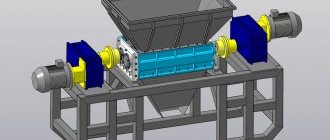
Drawings and detailed analysis of some parts of a machine made of wood.
Wood belt sander (click to enlarge)
In order for the tape to be located strictly in the middle of the shaft, the diameter of its central part should be 2–3 mm larger than at the edges. And to prevent the tape from slipping on the drum, it is necessary to wrap a layer of thin rubber on it, for which you can use an old tire from a bicycle wheel, having previously cut it along its entire length.
The sanding belt for such a machine, the optimal width of which should be 200 mm, is made from ordinary emery cloth. The standard cloth is cut into strips of the required width, and an abrasive tape is already glued from them. It should be borne in mind that the material is glued end-to-end; for this purpose, dense material is placed on the reverse side, which will strengthen the resulting seam. The properties of such a seam are greatly influenced by the glue; it must be of very high quality, then the material will not tear along the seam after a short period of use.
Several more options for manufacturing belt grinding machines can be seen in the video below.
https://youtube.com/watch?v=opM1afRob6o
Creating a belt sanding machine
In fact, there are only two main assemblies for a belt sanding machine - one with a vertical placement of the working part of the abrasive belt, as well as a horizontal one. Among those who make grinding machines, the first option is popular because the device is suitable for many types of processing processes, and is even more convenient for sharpening tools. In addition, dust is discharged downward during the process. Most craftsmen often use not metal, but wood or even plywood as the material for creating the frame, rollers and main parts.
The wood option has many advantages:
- All components and parts can be made in a carpentry workshop.
- Adjusting wood parts is much easier.
- Wooden construction is lighter.
- The device is vibration-resistant and can be easily disassembled if necessary.
In order to independently manufacture a reliable, efficient and safe grinding machine, you should have at least minimal engineering knowledge and skills in processing construction materials. For this reason, further we will consider only the very important aspects of creating and assembling the machine, and its schematic layout is presented in the picture below.
Selection of electric motor
As a drive for a homemade grinding machine, or rather a machine, they usually use electric motors from drum washing machines that have failed, as well as hand-held electric tools. If we talk about the former, their power is usually approximately 0.3 kW with a rotation speed of approximately 3000 rpm.
They are convenient for installation work, as they are equipped with special fastening lugs on the body with holes, as well as a thread on the shaft for a pulley attachment. Electric tools (as a rule, we are talking about grinders and drills) are attached to brackets or removable clamps. Their motors will operate at higher frequencies, and for this reason, in grinding machines, the best option would be to use models where it is possible to adjust this parameter.
In a drill grinder, the speed of the electric drive is one of the most important characteristics of a homemade machine, because the diameter of the drive pulley, which transmits the rotation of the sanding belt, will be calculated from it. All types of abrasive belts are designed for use at a certain linear speed, and its indicators are measured in m/s, and the operating speed will be equal to the peripheral speed of the drive pulley.
For this reason, if you have an electric motor with known data, the creation of a grinding machine project must necessarily begin with the fact that you decide on the diameter.
Please note that based on the length of the sanding belt and the diameter of the pulleys and rollers, you can calculate their center-to-center distances, and also determine the overall size of the future grinding machine.
Frame (bed) and its structure
Now a little about the frame. It is also called the frame of a grinding machine, and it is a supporting structure on which the electric drive, rollers and pulleys are mounted. The normal movement of the abrasive belt, as well as the stability of the device, will depend on its rigidity and precise manufacturing. The contours of the frame, as a rule, repeat the pattern of rollers (called kinematic), which are located at its extreme points.
After this, its design will be examined using the example of a homemade device made of plywood and wood, in which an electric drill is used as a drive. You can see the process of creating such a grinding machine in detail in the video, and at the end you will find sketches of all the parts in real sizes.
The machine bed is a box-type structure, with a drive pulley and a pair of rollers located inside it. It is made of a broken-shaped side panel in the shape of the letter “C”, which is installed on a large base. The material used for each part of such a grinding machine is plywood with a large thickness.
A work table with a slot for an abrasive belt is attached to the lower ledge of the bed. The drive pulley is installed on the vertical part of the frame, and the guide roller is installed at the end of the bottom; the regulating and tensioning element is located at the top. A similar figured sidewall is attached to the hinges in the form of a door, and also fully covers the entire space with the rollers and pulley.
The huge advantage of such a belt sanding device is that all its parts are made using the simplest tools in a carpentry workshop, and during the assembly process a minimum number of types of fasteners and metal components are used. As you can see, the master will spend no more than 2 days on its production.
Please note that if you look at everything from a safety point of view, then the solution to completely cover the rollers and belts is optimal. And the noticeable disadvantages of such a machine include only a small amplitude of the belt tension.
Roller installation
Homemade and factory-made belt sanding machines usually use 2 to 4 rollers of different sizes. One of them will always be a pulley on the drive axis and constantly transmits movement to the sanding belt. Another one will act as a tensioner (sometimes this function is combined with axial adjustment).
The rest are guides and are also capable of adjustment. One of the most popular is the design of grinding machines, which have three rollers. In this case, everyone will perform one of the functions. In such a configuration, when the working part of the abrasive belt for grinding is placed vertically, there will be a tension roller at the top and a guide roller at the bottom.
A belt grinder made from a drill with your own hands also needs to be configured. To do this, after installing the rollers and pulley, it is necessary to carry out adjustments on the machine frame. During operation, the sanding belt will move at a speed of 10-30 m/s, and every deviation in the geometry of the relative placement of the rollers and pulley can cause breakage and derailment.
For this reason, their axes must be set exactly parallel to the horizontal, and the planes of rotation along which the tape will advance must clearly coincide in the verticals. The possibility of such adjustments must be foreseen in advance during the development of the design of a belt grinding machine.
Brief instructions
Despite the simplicity of the design, such a machine will always cope with all the tasks assigned to it, and if you do not have funds in your budget to buy a factory machine, then a homemade device will be an excellent assistant for you. First, you need to use a crown to cut out 6 thick round parts and four thinner round pieces.
Although in this case all the calculations are based on how thick the sandpaper is (which can also be made as you go), you can modify such a machine and adapt it to your needs. In addition to the round parts, you will need a hairpin on which you will string the circles. Next, you need to glue the round parts together and glue them to a metal pin. As a result, new parts will be obtained.
Next, take a couple of small pieces of plywood and make a small diameter hole in one for self-tapping screws, and in the second, drill a hole for the nut with a pen. All that remains is to drop a little epoxy resin and hammer into the nut. Next, coat the edge of the second part with adhesive, and connect both parts to each other, secure with self-tapping screws. You should also make a couple more holes on the part you won't be drilling on.
Four such connections should be made. Afterwards we make a belt for sanding, and for this you need to cut off regular sandpaper as in the photo, apply glue to the inside and fasten it to the fabric. Then start assembling the machine. Make holes on the plywood, secure the first part with bolts and put one of the “drums” on it.
Then support the drum with the second part and secure it with the bolts. For such a drum, the pin on the inside should be longer - this is where you will connect the drill. On the other side we do the same, but here we will use parts with oblong holes.
Next, fix the rectangle with the circle cut out in it, insert the device into the mounting socket and connect the pin to the drill chucks. All that remains is to fix the pin in the socket and that’s it, the device is ready!
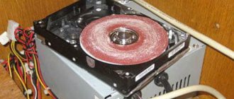
Making a grinder from a computer hard drive + (Video)
Any old hard drive can be converted into a miniature grinding machine. To do this you need to follow these steps:
- completely disassemble the hard drive and remove from the case everything that is located to the left of the magnetic disks;
- cut out a working circle from sandpaper, make a hole in the center of the circle for the spindle;
- stick several strips of double-sided tape onto the rotating disk of the hard drive and secure it with sandpaper;
- make a protective screen to protect the eyes from the possible ejection of the manufactured sanding disc;
- connect the finished design to the power supply from the computer and use it.
Of course, this design does not have high power, but it is quite possible to sharpen a small knife or scissors.
Introduction
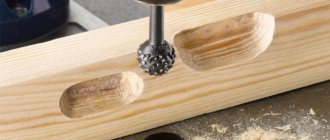
Drilling a thin workpiece is not a problem - even if the drill is not perpendicular to the drilling plane, it will not be easy to visually notice that the hole is not level, so, as a rule, the master will be satisfied with the result. In such cases, you can drill “by eye”. When the depth of the hole is large, then even with a slight deviation of the drill from the perpendicular, the “curvature” of the hole will be noticeable. For such cases, it is necessary to use special devices, or better yet, a drilling machine. Therefore, this time we will try to make a homemade machine from a drill or screwdriver.
Making a belt sander with your own hands + (Video)
Making a belt sander yourself is not at all difficult; you need to complete the following steps:
- select suitable materials and parts;
- create a reliable basis for securing the tool;
- install a suitable tabletop;
- secure the vertical posts with tensioner and drum;
- mount the motor and drums;
- secure with sanding tape.
To process fairly large parts and elements, it is necessary to make a large copy of a serial grinder. For example, if you take an electric motor with a power of 2 kW or more powerful with a rotor speed of 1500 rpm, then you don’t need to install a gearbox. The power of such an engine is quite enough to rotate a drum about 20 cm in diameter and process parts of about 2 m.
You can also use an electric motor from an old washing machine. In this case, the frame is made from a thick sheet of iron, preparing a place for installing the motor and carefully securing it with bolts to eliminate vibration. The design of such a machine consists of 2 drums, one of which is fixed, and the second can be tensioned and rotates on bearings around an axis. It is advisable to make the base for the machine from metal or several sheets of thick plywood. The drums are made on a lathe from chipboard. The tape is cut from sandpaper sheets about 20 cm wide and secured to the frame. The larger the table size, the larger the parts can be stacked and processed in the future. Drawings of finished products can be found online.
Existing types of grinding machines
The industry produces several types of machines, differing both in design and purpose. Here are the main ones:
- Eccentric or orbital, in this case the base of the tool simultaneously rotates around its axis and along a certain orbit. It turns out that each time it passes in a slightly different place, so scratches and burrs are rubbed out more and more with each pass.
- Vibration model. Here the working sole carries out reciprocating movements with a frequency of about 20,000 movements per minute. It is through these movements that grinding occurs.
- An angle grinder, which is popularly called a “grinder”. Using this tool, rough processing of parts, large logs, etc. is carried out. Abrasive wheels of the required grain size are used for processing.
- Belt sander
, which is usually used for work on large surfaces. Structurally, it consists of rollers driven by an electric motor, on which sanding tape is worn.
Photo of a do-it-yourself drilling machine
Making a grinder from a grinder
Many may say that the “grinder” is the same as an angle grinder, but there are some subtleties hidden here. It should be borne in mind that the angle grinder has very high speeds and often quite a decent weight. To polish a surface with a grinder, you need to have considerable experience in this matter and use special polishing discs and circles. The grinder has much lower engine speed and weight. To operate a factory grinding machine, no specific experience or skill is required. You can independently make a good grinder from an angle grinder, which is not inferior in its parameters to a factory machine, only by modifying its electrical circuit, by installing the regulator at lower speeds and by using special grinding attachments.
Tips from service technicians
It is recommended to make such machines only from metal elements - bed, pressure sleeve, stand. Wooden construction is easier to assemble, but has a shorter service life. It can fail even from minor mechanical damage - accidental impacts.
In addition, a wooden stand can withstand less pressure; using such a machine it will be more difficult to drill a hole in solid material.
It is recommended to choose a drill model only from a series of professional tools designed for long-term and frequent use.
You should think in advance about the fact that you may have to process particularly durable materials, so it is better that the drill has an impact function.
It is important to understand that the power of a hand drill and its speed of rotation are significantly less than that of electric motors on industrial machines. Therefore, you should not overload the tool to avoid burning its motor.
To learn how to make a machine out of a drill with your own hands, see the following video.
Let's block ads! (Why?)
Manufacturing algorithm
Considering that home machines will be interchangeable in terms of the type of processing, and the decisive role will be played by the attachment installed in the drill, we will consider two main options for home-made units - horizontal and vertical.
The procedure for assembling a vertical machine is as follows.
- Cut a square base 50 by 50 cm from a piece of metal or wood, with a thickness of 10 to 20 mm.
- Drill a hole in it exactly in the center at a distance of 1-2 cm from the edge for mounting the stand. The diameter of the stand must be at least 5 cm.
- Install the stand, center it using a level and weld it with a welding electrode. If you are making a wooden machine and the stand will be wooden, then firmly fix it with self-tapping screws.
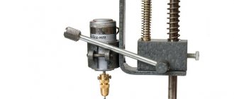
- Using metal clamps, secure the drill to a movable element that will be put on the stand, forming a lowering/raising spindle.
Place the spring on the strut. Its length must be at least 2/3 of the rack. Having placed the drill on the stand, mark the place where the drill will hit when lowering the spindle. According to this place, cut two through hollows in the frame crosswise. A table is installed in the groove on the threaded pin on which the workpiece will be mounted. A nut is screwed onto the pin from the bottom side; it will fix the table in the desired position.
You can also attach the table to the pin from the outside with a nut, recessing it into the surface of the table so that it does not interfere with the placement of workpieces. It is important that after securing with a nut, the length of the outer part of the pin is flush with the top surface of the table.
The assembly algorithm for a horizontal machine looks like this.
- Cut a rectangular frame - dimensions are determined individually.
- At one edge, secure a seat for a drill with a hollow in the upper part corresponding to the size of the tool.
- Secure the drill to it with a clamp.
- Cut a through groove for the pin along the frame, and install two metal corners along the edges along which the pressure sleeve will move.
- The width of the pressure sleeve must exactly match the distance between the guide angles (runners). A threaded pin is screwed into it from below, which will move in the hollow.
- By moving the sleeve close to the drill chuck, determine the place where the special headstock will be installed for fixing the workpieces.
- Attach the headstock to the bushing with a metal cone-shaped pin placed in the center.
- The sleeve is fixed in the desired position (for clamping the workpiece) with a nut screwed onto the pin from below.
In both options, it is necessary to provide special adjustable legs for the frame.
If the bed rests flat on a workbench or table, it will become impossible to adjust and fix the clamping sleeve on a horizontal machine or the workpiece table on a vertical one.
Other functional parts
Their list is as follows:
- Base plate. Absorbs elasticity waves.
- Drive board for vibration damping.
- Comb stops (combs). Needed to neutralize vertical vibrations of the workpiece.
- Static side stop. Guarantees the correct feeding of the part and the depth of its horizontal processing.
- Dust catcher.
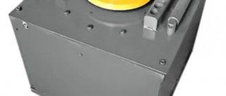
Drive unit
It is better to make the opening for placing the drive round, so the machine will have less vibration during operation. The motor must not come into contact with the plate.
Installation of the drive in this plate is as follows:
It is better to create the drive board from PCB or fiberglass with a density of at least 1.5 cm.
Thick plywood (1.9 cm) treated with a vibration-absorbing agent is used for the slab.
The board and the plate are separated by a gap of 0.5 - 1 mm. It is desirable for the engine to have mounting feet, and they should extend beyond the body. This will allow the cutter to move upward. To install it, long motor bolts are used. The removal of the cutter is ensured as follows: steel washers with rubber gaskets are put on the bolts in turn between the engine housing and the suspension cushion.
Emphasis
Suitable material for the stop is thick plywood (from 2 cm). It is required to drill 3-5 holes for combs and risers. The first two are located 5 mm from the extreme sides of the cutout for the cutter. Others - after 2.5-3 cm. The positions of the stops depend on the parameters and quality of the workpiece.
The side support diagram is as follows:
It can have this configuration:
System elements
- A 15-20 liter bucket with a tight lid and snap-on latches.
- Pipe 1 – inlet. The diameter is 2 cm. Its end is beveled by 45 degrees and rotated by 25 degrees to the outside. It is placed 2 cm from the side of the container.
- Branch pipe-2 – exhaust. Diameter – 3 cm. Placed strictly vertically in the bucket. Its selective ending is narrowed to 1.5-2 cm.
- Vacuum cleaner.
Combs
Oak or walnut is used for combs, without fungi or defects. They are made on the right and left sides for ease of feeding the workpiece.
Drawing:
The length of the first tooth is reduced by 3 mm. The reason is that it acts as a rebound spring for the entire ridge. Without this, damage may occur.
The ridges are attached to the stop using a special bolt through a slotted hole.
The non-working element is fixed with a self-tapping screw to the same stop through hole D7.
To work, the comb is positioned so that it contacts the workpiece with all teeth except the initial one. Then it is secured with a lamb.
Types of do-it-yourself drilling machines
There are different types of drill presses made at home. They differ in: material of manufacture, structure, size.
And home craftsmen never stop coming up with new designs and selecting sizes for drilling machines. After all, not everyone makes machines according to ready-made drawings.
Here are some of the most popular drill press designs:
Wireless machine made of wood. This design is well suited for portable drilling of large items. Since the operation of the drill in such a machine is provided by the battery, it is necessary to make a special wooden box. The machine drawing is adjusted independently to the dimensions of the built-in drill.
Mini drilling machine. Making such a tool will not take much effort and time. This design is considered the most economical and does not require a large amount of materials. The model is designed depending on the size and shape of the drill; the drill itself can be secured with ordinary rubber bands or cable ties.
Machine made of plastic pipes. This option is good for those who have pipe scraps left after plumbing repairs. In another case, this option is very economical, since PVC pipes are cheaper than metal or wood. It’s not that difficult to make, the main thing is to maintain the proportions and dimensions.
Make or buy?
An electric drill is a ready-made drive, gear, spindle and chuck in a monoblock. Place it on the carriage of the machine and you can drill. In terms of accuracy, the solution, generally speaking, is not optimal (see below), but in many cases it is acceptable, but eliminates the need to order expensive turned parts of increased accuracy, see below. In view of this, frames for installing drills are now sold only on the street from trays; prices are affordable. When choosing one to make a drilling machine from a drill, be guided primarily by the operating mode of the equipment; The price also depends on it:
- Occasional drilling/milling for yourself with the accuracy of what you get - cast plastic bed or stamped steel. The feed mechanism is lever with a cranked lever (see below). Carriage sliding bearings (see below) are steel on steel or with nylon liners. Prices are $20-$30.
- Regular drilling for yourself or to order with ordinary machine-building precision. The materials processed are up to the hardness and toughness of ordinary structural steel. Everything is the same, but the sliding bearings are steel on steel (worse) or with bronze bushings, and the frame is cast iron or (more expensive) composite, also vibration-absorbing. Prices: $30-$40.
- Regular drilling and milling of any materials that can be tooled with periodic overloads of the tool and/or with increased accuracy - plain bearings are only bronze on steel, cast iron frame. The feed mechanism is rack and pinion (see below); vibration-absorbing console. Prices: $60-$180.
Choosing a bed
The stand for the drill (which sellers for some reason stubbornly call stands) must be chosen not according to - not “China”); Now the market is full of “German China”, not to mention products from post-Soviet states. The design needs to be checked.
First, samples with plastic non-nylon liners for sliding bearings are definitely rejected: runout and drill drift of more than 0.5 mm will appear already on the 10th – 20th “hole” and will further increase. The second is console play. We take it by the far end, swing it up and down and to the sides while holding the latch. There should be no noticeable “chatter” (the tactile sense of an untrained person feels a beat of 0.4-0.5 mm).
Next is an inspection of the structure, see Fig. below. For regular drilling, the one shown in pos. 1. The ideal option is at pos. 2: collet clamp of the drill, shifting the column to the side reduces the vibration of the console by an order of magnitude, and by turning it sideways by 45 degrees, you can mill the part by hand with the precision “as best you can” on a standard fixed table, removing a couple of table fasteners, because in this case, its manual displacement relative to the horizontal working axis of the console will be linear.
How to choose a bed (stand) for a drill
And here is a sample for pos. 3 do not take under any circumstances. Firstly, the collar of its column is low and its fastening is unreliable. Secondly, longitudinal grooves under the table facilitate manual milling “as it happens,” but, unlike diagonal ones, they do not dampen vibrations of the bed. Moreover, they will concentrate where shown by the arrows (the tide under the column is made too narrow) and from there they will go straight into the column and table.
Which is cheaper?
Bench Drill Press Spindle Drawings
Let’s say the price for the machine you like doesn’t suit you. Or a drill, if it’s a “crowbar” one, with an impact mechanism, that was used in work on building structures and the beating of the chuck is visible to the eye. Then the first thing we do is find out if there is a craftsman within reach who owns a lathe with high precision (no rougher than 0.02 mm). Which, by the way, is not a fact - a high-precision machine is very expensive and never pays off with the flow of regular orders. But let's say he was found. We take the drawing in Fig. on the right, we go to him and ask if he can turn it out of steel no worse than 30KhGSA, and how much he will charge for the work. “This” is the drawings of the tabletop drill spindle. The rest of its parts can be turned on a regular machine, or found in ruins at an iron market or in your trash. Most likely, it will turn out that it is cheaper to buy a bed + table, and if you estimate the costs for the rest, then perhaps a drill of increased accuracy will emerge. There are some of these on sale; they can be recognized by the absence of a striking mechanism and a collar specifically for installation in the frame: a turned steel cuff is put on it.
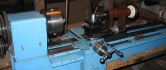
Original idea
This design is very versatile, since its basic part (base and spindle box) is the working part of several other devices described in the following articles:
- DIY wood lathe. Description, drawing, video.
- Do-it-yourself thicknesser machine: drawings, photos and videos.
- Homemade grinding machine from a drill (screwdriver). Description, drawings, video.
These articles contain photos and videos of do-it-yourself machines.
| Turning | Thicknesser | Grinding |
Thus, part of the structure of the described machine can be used for the manufacture and subsequent assembly of three more additional devices. If necessary, having all the components, you can assemble the devices you need at the moment at your own discretion.
Preparing for work
Preparation for work is important, since it is at this stage that the full composition of the required tools, mechanisms, materials, fittings and fasteners is determined. It is at this stage that you need to make sure that you have everything you need so as not to interrupt or stop the work. Therefore, before starting, we recommend that you review the material in full and make sure that everything is available.
Tools
During the work you will need some hand and power tools, let's check the list:
- Tool for straight sawing: Circular saw or sawing machine.
- Jigsaw.
- Screwdriver.
- Additional hand tools: hammer, clamps, square, screwdriver, marking pencil, etc.
Materials, fittings and fasteners
To make a drill-based grinding machine you will need:
- Plywood 15 mm thick. Chipboard can also be used.
- Wing nut – 2 pcs.;
- M6 bolt and self-tapping screws.
Main structural elements
The main structural elements of the grinding machine are:
- Base:
- Frame;
- Spindle box;
- Sanding table;
- Drill (or screwdriver);
Characteristics that a belt for a sanding unit must meet
Selecting an abrasive strip is an important step when assembling a mini-grinder with your own hands. First of all, you need to decide on the length of the tape and its width. The geometric parameters of the strip are influenced by two main factors:
- grinder dimensions;
- purpose of the unit.
Fabric base withstands surface tension better
Endless abrasive strips are also classified into grit types. The length of the sanding strips can be different (from 610 to 1830 mm). Such tapes have a width of 50 or 100 mm. The first option is most often found in units assembled by hand at home.
A high-quality abrasive strip must have an elastic fabric base
When choosing the right tool, you also need to pay attention to how many revolutions the strip can withstand. It is recommended to purchase products that can operate at 1500 rpm
This option is best suited for making a belt grinder with your own hands. The drawing drawn up earlier must contain information about the dimensions of the abrasive strip and its other characteristics.
A good tape must have high abrasive resistance. The wear resistance of the tape depends on this indicator. For homemade machines, it is recommended to use belts whose length is no more than 123 cm. The abrasive strip must not only be resistant to wear, but also have good resistance to high temperatures generated during friction against the workpiece during operation.
It is worth noting that short-length tapes are much more susceptible to wear than longer products.
Experts advise paying attention to pictures depicting finished products. Photos of the machines allow us to answer the question of how to make a grinder with your own hands
The design of the device can be significantly simplified if ready-made elements purchased separately are used in its assembly.
The speed and quality of product processing depends on the choice of tape.
And finally, special attention must be paid to the place where the abrasive tape is glued. The junction of the two ends of the strip should be as neat as possible, without any defects or protrusions
How to glue the tape for the sanding unit yourself
Belt grinders contain a spring, which performs a very important function: it tensions the belt that has sagged due to wear. The belt is changed several times even when processing a small workpiece. This should be remembered.
When assembling a grinder with your own hands from plywood or metal, you can make an abrasive strip yourself. Gluing such tape is a complex undertaking that does not tolerate mistakes. There is a lot of advice on the Internet on how to properly glue tape, but many of them are incorrect.
The gluing process is as follows. First you need to select a fabric-based sanding material. Then you should prepare both ends of the abrasive strip. To do this, they are cleaned. The seam on the strip is made exclusively using the butt method. Experts definitely recommend reinforcing the glued tape from the inside with a thick strip of fabric, which is fixed with a special adhesive composition.
Gluing tape is a complex process that does not tolerate mistakes.
In order to connect the ends of the abrasive strip, you need to purchase a special adhesive composition. The best option is to use elastic glue. There is no point in saving money, since cheap products, as a rule, are not of good quality.
Before gluing, it is necessary to prepare a strip for sanding tape. A do-it-yourself grinder (from scrap materials) needs a reliable abrasive strip, which is difficult to do at home. The process is carried out using a glue stick, which is installed on hot-melt guns. First, the composition is heated. To do this, you can use a regular hairdryer, which is found in every home.
The need to make a homemade drilling machine
The best types of homemade drilling machines presented in this article are not inferior in quality to industrial models.
At the same time, simple designs are distinguished by accessible functionality; with their use, it is possible to drill to a certain depth.
This could be restoring the functionality of vehicles or equipment, carrying out large-scale or cosmetic repairs around the house, or restoring utilities.
General information
Certain types of homemade grinding machines have a fairly simple design, and you can assemble them as needed. The rest are very similar to industrial designs and are an unusual example of the beauty of home engineering.
Old electric motors from household appliances, as well as driven electric tools, are most often used as drives in such devices. Very often with conventional grinding. The drive part of the machines is made on the basis of a grinder or an electric drill. We propose to consider how to make a belt sander from a drill with your own hands.
Features of the use of machines
Working with a drill while holding the tool only with your hands significantly limits its capabilities. The weight of the tool and vibration do not allow the drill to be firmly fixed in the desired position. But if you think through and design a special frame where it will be firmly attached, then an ordinary hand drill will turn into professional, almost industrial equipment.
From a drill you can make the following types of machines yourself:
- drilling;
- turning;
- milling;
- grinding.
Moreover, after replacing the working or cutting element, the machines become interchangeable. They provide a two-in-one function, for example, a drilling and milling machine, a lathe and a grinder. It all depends on the installation conditions and the needs of the owner.
The power of the machines and their capabilities will depend on the type of drill (the power of its electric motor), the method of fastening, since in this case it is the main working part of the equipment.
Options for homemade designs
Making a grinding machine with your own hands is not difficult. The main thing is that it corresponds to the types of work that the master plans to perform. From an economic point of view, it is better to take components that are on hand. If you have to buy the components of the device, then the budget of a home-made device will be comparable to a factory model. All other things being equal, it is better to give preference to an industrial tool, because its quality is disproportionately higher.
Let's look at a few handmade devices. Perhaps one of them will suit you.
Do-it-yourself grinder from an angle grinder
As the name suggests, the grinder is designed for grinding. Cleaning discs successfully cope with rough work: removing old paint, removing metal deposits or traces of corrosion. For finer cleaning, special attachments made from sanding sheets of various grain sizes are sold.
Models for domestic use operate in one mode, and the number of revolutions reaches 15 thousand per minute with an average of 11 thousand. This speed is great for sawing materials, but it is too high for sanding work.
The grinder's motor has excess power. For polishing, 300–400 W will be enough.
A grinder made from an angle grinder will have more weight compared to a factory tool, but it is possible to adapt a homemade one for yourself, which will increase comfort when grinding.
For an angle grinder, you can make a simple attachment that will turn the device into a miniature belt grinder. In this case, work is carried out without a protective casing.
If you do not want to use devices, you can adjust the number of engine revolutions. Independent modernization of the circuit will require specialized knowledge in electrical engineering.
On professional devices, you can set the number of revolutions manually, however, their cost starts from $200.
Making a grinder from a drill
You can use a drill to build a productive belt sander with your own hands. In this case, the tool acts as a drive. The design itself is simple and does not require significant investment. To make it yourself you will need the following materials:
- metal rods with and without threads;
- profile pipe;
- plywood;
- steel sheet;
- bearings;
- hardware;
- wood glue.
You should make sure that you have metalworking tools, an inverter and devices for sawing metal.
Stages of work:
Manufacturing of pulleys. The driving and driven pulleys are designed to transmit torque from the drill to the grinder. They are made from plywood.
By changing the diameter you can obtain the desired torque. One pulley consists of several round timbers, which are connected using wood glue. In the center it is necessary to drill holes for steel rods. After the glue has dried, the workpieces are modified by making a groove that must correspond to the width of the drive belt.
Manufacturing of drive and driven shafts. They are also made from plywood, similar to pulleys. More round logs should be prepared for them.
Assembling the lower part. To do this you will need a profile pipe. First of all, it is necessary to make mountings for the bearings and connect them. This is the base for the working shaft.
Making the top part. The tension mechanism will be attached to it.
We make the thrust part from a steel sheet.
Drive installation
Please note: for normal work it is better to take a powerful drill. Finishing work. All that remains is to install the pulleys, tension the drive belt and assemble the protection
After this, the hand-assembled device needs to be coated with paint.
For small and precise work, it is better to purchase compact drum or plate type attachments, depending on the type of work.
Homemade grinder from a computer hard drive
From an old hard drive you can assemble a small grinding device, the main advantage of which will be the complete absence of investments, with the exception of the cost of abrasive wheels. The DIY manufacturing process is as follows:
- Open the case and remove all elements located next to the magnetic disk.
- According to the size of the upper part of the drive, cut out a circle of sandpaper of the desired grit.
- Using double-sided tape, secure the paper to the surface of the disk.
- We make a casing that protects from dust or abrasive grain.
- To start the design, the hard drive must be connected to the computer's power supply.
What should it consist of?
A basic unit can be made from an ordinary drill. You can add additional devices to it - for example, a milling unit. But each machine must consist of several required elements: a drill, a countersink, a reamer and a tap.
There are many types of drilling units in industry - semi-automatic, spindle, vertical and others. In everyday life, the so-called mini-additive unit with a modest set of tasks is most often used. Before you make a homemade drilling machine at home, you need to understand the functions, basic elements and general operating principles of this type of mechanism.
By function, the most popular devices are spindle machines, the main function of which is to transmit rotational motion to the workpieces. In second place in popularity are devices for horizontal and radial drilling. An apparatus for boring parts is also common. With such functional diversity, drilling equipment is generally classified as a device for universal use.
But with this freedom there are a number of mandatory components, without which there are no drilling machines in principle:
- bed;
- steering rack;
- engine.
Multifunctional device - miter box
By making the work table for your angle grinder more rotatable, you will get a multifunctional device - a miter box.
This device allows you to work not only with wood, but also to cut profiles, baseboards, baguettes and other workpieces at a certain angle. To make such a part, you need to install the working disk on the grinder and fix the table at an angle of 45 degrees. It is worth noting that such a unit is considered a real salvation for those who need to cut a large number of window casings, skirting boards and glazing beads. A miter box in combination with an angle grinder allows you to work even with paving slabs in a diagonal direction. And this, in turn, helps to diversify styling options.
Portable mechanism from a hand drill
It is very convenient to use a drilling machine from a hand drill in cases where it is not possible to connect an electric drill to a power source. To make the machine, you can use a wooden frame:
- the base is made of boards 30x20 cm and 40 mm thick;
- a vertical board is attached strictly at an angle of 90 °C;
- the vertical wall should also be made of a thick board, at least 30 mm, and metal corners and screws will help secure it securely.
Metal runners are attached to the vertical wall (they can be taken from old furniture or bought in a store), and a hand drill holder is attached to them. This way, the drill will move up and down freely, however, this is not enough. To prevent the drill from falling under its own weight, a spring of the required elasticity is attached to the drill holder and the base of the machine.
Don’t forget about the handle that you will need to turn. Nothing should hinder its movement. The result should be a unit that is driven manually and does not require power.
Design
There is nothing particularly complicated in the design of a belt grinder. The device consists of a motor, drive and guide rollers. A sanding or roughing belt of the required grain size is passed through them.
When the engine is turned on, the drive roller mounted on its shaft begins to rotate, and through the tensioned working belt, the rotation is transmitted to the guide rollers. By pressing the part to be processed in the working area against the belt, the operator performs the required operation, changing the position of the workpiece relative to the surface of the belt if necessary.
By adjusting the distance between the guide rollers, it is possible to process surfaces with defects of different depths. During prolonged use, the sanding belt may not stretch much. To compensate for possible slack, a tension mechanism is provided in the design on one of the rollers. Typically, such a function is assigned to a roller located at the same distance between the leader and the slave.
The grinding machine is supplied with a support table, which also serves as a surface for fixing the workpiece. As a rule, such a table should be able to rotate 90 degrees about one axis. In this case, it is possible to process two perpendicularly located planes without reinstalling the part on the support table.
Of course, a grinder control panel is required! For safety reasons, it is recommended to mount it on the machine frame in close proximity to the operator’s working area. Portable machines are equipped with a stand made of durable steel with mounting holes on the base, allowing you to fix the unit on a wooden surface.
If you look at the design details, you can immediately notice some visual instability of the assembled grinding device. The overhang of the side dimensions of the installed rollers significantly exceeds the supporting surface on the base. In addition, the absence of a support table makes it difficult to effectively process relatively large surfaces, and holding the part in a canopy is inconvenient and quite dangerous.
An increased length of the working belt leads to additional losses due to friction. It is necessary to use a higher power power unit in the drive, and this increases energy costs. The tension unit is simple and functional. Adjusting the tension is a matter of seconds. The machine comes with replaceable sanding attachments, which can be used for sanding even on internal surfaces. Despite this, the cost is 100 thousand rubles. makes me think.
Required materials and tools
The torque-creating element, and accordingly the main working part in each type of machine, is the drill. The type of processing will largely depend on the attachment installed in its cartridge. Therefore, identical materials will be needed to assemble them.
To assemble a lathe, grinding machine:
- rectangular metal or wooden base, bed;
- clamping sleeve;
- a clamping head, which will be attached to the drill chuck;
- runners for the pressure sleeve;
- seat for fixing the drill.
Materials for assembling a drilling and milling machine:
- square bed;
- a metal stand on which the spindle with the drill attached will move;
- a spring corresponding to the diameter of the rack;
- table for workpieces;
- pin for fastening the table.
Tools you will need:
- screwdriver;
- pliers;
- hacksaw for wood or metal;
- fastening elements - bolts, screws, nuts;
- welding machine.
If you plan to make a metal machine, then a necessary condition will be the presence of a welding machine. Since the machine is intended more for home use, its drawings and dimensions of its component elements are set individually.
Safety precautions when working on a sanding grinder
Like any other work on any other machines, grinding on a homemade belt sanding machine is subject to fairly strict safety rules that must be strictly adhered to.
The principle of operation of the grinder.
These rules are as follows:
- It is strictly forbidden to touch anything that moves with your hands while the machine and working surface are operating.
- Wear safety glasses while working to protect against hot abrasive particles.
- Carefully check that the connections and fastenings of all moving parts of the grinder are tight.
- Monitor the condition of the braiding of electrical wires.
- A protective casing is a must, even though it slightly narrows the viewing angle.
Grinding accessories
True, this is more common in a car, but you can also encounter this during ordinary apartment renovations. So, to tighten and unscrew screws in hard-to-reach places, a special drill attachment is used, which is called a “flexible shaft extension.” One end of the flexible shaft is fixed in the drill, and the other is a magnetic bit holder. You install the desired bit into the holder, and now, your tool for tightening screws in hard-to-reach places is ready:
Mixer functions.
When you really get involved in renovation work, you will be faced with the fact that you will constantly need to mix something: wallpaper glue, cement-sand mixture (CPS), floor leveler, glue for gluing tiles, plaster, putty and other. I’ll tell you right away that you can’t do this with your hands. Firstly, you will quickly get tired, and secondly, you will never be able to mix cement mortars with your hands to the state of thick, smooth sour cream! Therefore, a drill and a mixer come to the rescue. The mixer looks like this: Installed in a drill, the mixer looks like this:
How to use an impact drill
Before you start working with an impact drill, you need to set up the tool and prepare everything you need for work. Now I will talk about my drill, but for other drills the principle will be similar.
Setting the operating mode. First, understand what type of work you have to do. An impact drill has only 2 main modes - drilling mode and chiselling mode. In accordance with this, you need to set either a “drill” or a “hammer”. Let me immediately note that you set the hammer only for operating the drill in hammer drill mode. In other cases: drilling, grinding, tightening screws, mixing cement mortars is done when the switch is set to the “Drill” position.
Speed setting. For different types of work you will set different speeds. For example, if you need to drill holes in a metal plate that you want to use for a bracket, then it is better to turn on the 2nd speed. If you are going to mix cement mortar or want to tighten screws, you need to set the 1st speed. If you are going to work with a cord brush, then usually when purchasing attachments, the recommended operating speed is indicated on the packaging. Thus, you can navigate in choosing the speed. If you suddenly don’t know what speed to set for a certain type of work, consult with professionals.
Reverse setting. For all types of work, except for unscrewing screws, the direction of rotation of the drill chuck should be clockwise. To do this, the reverse switch must be set to the position where the arrow points to the cartridge.
Installation of the nozzle. Depending on the nature of the work, you install the desired attachment on the drill. I have been telling you about attachments throughout this book. So, just look at the desired section.
While working. The drill is started by smoothly pressing the start switch. (See Impact Drill Design section.) Moreover, the harder you press, the faster your drill accelerates. When pressed as hard as possible, the maximum speed will be the one you set when selecting the mode: “1st speed” or “2nd speed”. Thus, by switching the starting switch and switching speeds, you achieve a very wide speed range. If you have been drilling a surface for a long time and are tired of pressing the start switch, then for these purposes press the “Lock button” by releasing the start switch. In this option, the drill will continue to work. This is convenient because... saves your energy. You can disable this mode by pressing the start switch again.
Finally, if you are unscrewing a screw, then set the reverse switch to the position where the arrow points towards your hand. When the drill is turned on smoothly, the chuck should rotate counterclockwise.
Dangerous experiments
An impact drill will be your indispensable friend and assistant in many jobs. But there are still things that are unacceptable in operation, and I will now briefly talk about them. We will talk about a circular saw blade, which, for some reason, some people also want to install on a drill, thus building an electric saw:
Remember the rule: do not put a saw blade on a drill. Firstly, because there is no protective casing. Secondly, there will not be the necessary pressure on the material being processed. Thirdly, the drill will “walk” in your hands, and if the saw lies unevenly on the surface being sawed off, then either the disk will fly apart, or the drill will be torn out of your hands, and no one knows where it will fly! Injury guaranteed! This is very dangerous and let's not experiment like that!
Making a grinder from a grinder
Many may say that the “grinder” is the same as an angle grinder, but there are some subtleties hidden here. It should be borne in mind that the angle grinder has very high speeds and often quite a decent weight. To polish a surface with a grinder, you need to have considerable experience in this matter and use special polishing discs and circles. The grinder has much lower engine speed and weight. To operate a factory grinding machine, no specific experience or skill is required.
You can independently make a good grinder from an angle grinder, which is not inferior in its parameters to a factory machine, only by modifying its electrical circuit, by installing the regulator at lower speeds and by using special grinding attachments.