Most finished projects and drawings of public buildings in editable formats are dwg format for AutoCAD. Also available in Inventor, ArhiCAD, Compass-3D and others. Select building type:
Vibrating platforms / Woodworking / Galvanic / For film application / Grinding / Rotators / Manipulators / Friction machines / Winding / Threading / Accessories / Body straightening / Press / Piercing mills / Boring / Cutting / Drilling / Mill / CNC machines / Planing / Lathe / Forming / Milling / Tire / Grinding
Features of wood lathes
In a number of cases, a hardworking owner has a desire to make furnishings and utensils that have a circular cross-section throughout their entire length.
Most often these things are:
- Holders for hammers and files;
- Stair posts, flowerpots, handles for railings;
- Rolling pins, potato presses, grape crushers;
- Vertical pencil cases;
- Cups, mugs, saucers, plates, trays, stoppers.
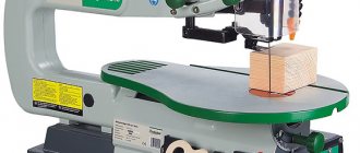
It will be impossible to cut such things with planes and saws. In this case, you will need at least the most primitive machine.
Design
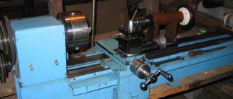
Although the first turning machines appeared at the end of the 18th century, their architecture was so perfect that it has not undergone significant changes to this day. We can say that today we use equipment similar to that used for metalworking two centuries ago.
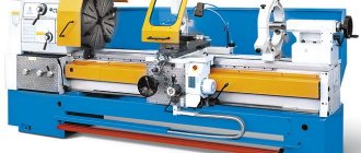
Design of a screw-cutting lathe
A metal lathe consists of the following components and parts:
- The bed, which is the basis for all other elements. The precision of processing and the versatility of the device depend on the strength and scrupulousness of its manufacture. The body of the machine must be a massive, fundamental structure. Only in this case can vibrations and tool displacement be avoided during turning operations.
- Front spindle headstock. This unit allows you to fix the workpiece and rotate it during processing. Often the spindle head includes a gearbox and a feed mechanism for the caliper or machining head. This allows you to change the rotation speed of the part and improves productivity.
- Tailstock. This element is designed to hold the part in a given coordinate system, coaxial with the spindle. In addition, the tool mounted in the tailstock allows you to perform additional operations, for example, cutting threads.
- Caliper. Without a doubt, this unit is one of the most important in the design of the machine. The support is designed to hold the cutting tool and move it relative to the workpiece. Depending on the design, the support can feed the cutter in different planes, making it possible to produce parts with a complex configuration of internal and external surfaces. The main requirements for the support are reliable tool retention and feed accuracy, since this is directly related to the quality of processing.
When making a homemade lathe, the design is simplified as much as possible. To do this, elements that are problematic to make at home are modified, and some components are completely abandoned. For example, the gearbox can be replaced with several pulleys of different sizes, and the automatic feed can be excluded from the circuit.
Buying a lathe
Today you can purchase such a device with a click of the mouse by going to a specialized online store. True, such a purchase will hurt your pocket, especially if you choose a high-quality model and not a cheap Chinese craft.
However, this does not mean that the idea of founding a miniature workshop will have to be given up. The problem of high cost can be solved by taking a different route. A simple and durable electrical unit must be made by hand.
Turning round architectural decorations
Such a mechanism will be an excellent help if you need to make inexpensive repairs to a cottage equipped with
- Flights of stairs with wooden balustrades;
- Decorative trims;
- Carved shutters;
- Window earrings.
Pipe feeding manipulator in the OXYGEN converter shop of the Magnitogorsk Iron and Steel Works
termist
February 2, 2021
- 0
725
Includes: PowerPoint presentation, video file with animation of the manipulator, drawings, calculation and explanatory note. The diploma project proposes the modernization of the drive for moving the carriage and the rotation mechanism of the boom of the manipulator of the protective tube at the casting site of CCM No. 4 of the oxygen-converter shop of OJSC MMK (Magnitogorsk
Metallurgy / Machine tools
Profitable and promising business
Having gained some experience in the production of decor, it will be possible to move from banal savings to a profitable business. This could be the production and sale of chess pieces. If you sell them through online auctions or retail chains, then an additional source of income will appear in the family budget.
Handmade items quickly find demand, especially if they are offered for sale at a reasonable price.
In the future, this hobby will develop into full-time commercial employment, giving you a chance to acquire professional tools and start earning very good money.
PROJECT OF ORGANIZING CAR SERVICE FOR PASSENGER VEHICLES IN VOLOZHIN
atf_rulezz
October 10, 2020
- 0
1 458
According to the assignment, the maintenance and repair zone for passenger cars was developed in detail. As a result, the area of the zone is 54 m2. In the design part, a VolvoS90 steering simulator was developed. A technological map has been compiled for replacing timing elements of the PSA DW8P engine.
Design of enterprises, sites, workshops / Machine tools
Main components
The most important components of such a device include
- Bed;
- Electric drive;
- Front and back headstock;
- Stand for accessories.
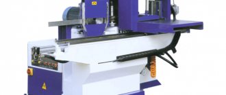
Modernization of mill 250
Marina Suetkina
August 31, 2021
- 0
209
Graduation project. Contains RPZ and drawings: layout diagram of the equipment of the small-section mill 250, boring boring cutter, hydraulic control unit, mounting plate, drive shaft, winder drum drive, bearing cover, cover (blank), technological adjustment diagram. Modernization by developing a winding device drive and
Metallurgy / Machine tools
Support frame base
The bed is a frame that allows you to connect all the parts into a harmonious mechanism. The strength and reliability of such a support directly determines the stability and durability of the entire device. It is better and easier to use a steel angle to make the frame; another suitable material is a rectangular profile.
First of all, it is necessary to mark the dimensions of the assembled automatic sharpening machine. These parameters are determined by what exactly this machine will be used for. As a rule, a stand for an apartment or garage modification does not exceed eighty centimeters in length.
Machine assembly procedure
Making any mechanism (installation, unit) with your own hands is a creative endeavor. Each master is guided by the range of tasks that he will have to solve with the help of homemade equipment, the availability of free space in the garage (shed, outbuilding), and so on. But if you understand the algorithm of actions, then assembling a lathe for domestic use will not be difficult. Here are some homemade samples.
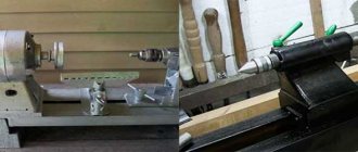
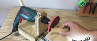
If the reader is completely satisfied with the simplest model, and there is no desire to waste time on design, the author suggests paying attention to a machine based on an electric drill. No additional explanation is required here.
It is clear that the functionality of such an installation is limited. Primarily due to the fact that you can only clamp a milling cutter or drill in the chuck. In fact, such a homemade product can be called a lathe conditionally.
But the manufacture of more “serious” equipment is worth looking into in more detail.
Table frame
It is necessary to determine whether the existing workbench (for example, in the garage) can withstand the additional load. If you plan to make a low-power lathe for processing small parts, then a workbench will be enough. When assembling the frame, two points need to be taken into account.
First, you need to weld nickels onto the table legs. If the mobility of the machine is not required, that is, it is not expected to be moved regularly, it makes sense to hollow out holes in the concrete floor, install the frame and fill it with concrete again. The goal is to ensure maximum stability of the structure during the metalworking process.
Secondly, you should not unnecessarily complicate the installation by using a thick steel plate as a tabletop, especially since we are not talking about powerful equipment. It is enough to weld the lathe bed to the frame. Strength will be ensured.
It is necessary to check the compliance of the upper cut of the support frame with the horizontal plane. And only after the structure has been brought back to normal can this working stage be considered completed.
bed
Everything is simple here - the lathe support frame (channel or angle) is welded to size.
Drive unit
Here you have to choose one of two options:
- If it is decided to attach the spindle (clamp, chuck) to the motor shaft, then how to change its speed? And this will have to be done, depending on the hardness of the sample being processed. You can, for example, install a motor from a used electric sewing machine (speed adjustment is provided). Only the power of such a lathe will be minimal, therefore, the possibilities are limited.
- Any electric motor is characterized by the rotational speed of the shaft (rotor). It is clear that regularly replacing the engine with another during operation is impossible. Therefore, you will have to think about how to change the drive gear ratio. The simplest solution is to reinstall the pulley belts attached to the intermediate shaft, that is, use this type of transmission.
“People's craftsmen”, focusing on this technique, make machines with their own hands for 10-12 speeds. Convenience in working with dissimilar materials is ensured, and there is no need to search for components, draw up an automation circuit and assemble it.
There is another argument in favor of such an engineering solution. The main force present in machines assembled by hand is along the axis of the shaft. But the bearings of electric motors of any model are designed for a “perpendicular” load.
If the machine does not have a belt drive, you need to be prepared for frequent repairs. The reason is the destruction of the supporting parts of the engine. It is possible to avoid this, but such modernization requires separate consideration (there are several options) and will significantly complicate the design process.
What to consider when assembling
For such regulation, it is advisable to install a motor with a power in the range of 0.75 - 1.5 kW on a lathe.
It is better not to use collector-type products. The peculiarity of such engines is that when the load decreases (for example, at the moment of retraction of the cutter), the rotor rotation speed increases significantly. The possible result is easy to predict - the workpiece will fly out and the worker will be injured.
As a rule, do-it-yourself lathes are assembled to work with small “blanks” - up to half a meter long and no more than 12 - 14 cm in diameter. For such models, asynchronous motors are considered the best (the recommended power is indicated). The stability of the speed will be ensured, and sudden changes in the rotation speed will be excluded.
Frame manufacturing process
The slats selected for assembling the frame must be laid so that their upper edges are strictly in the same plane. The parallelism of these guides is checked by measuring the distances between their ends on each side.
- Longitudinal fragments are secured with clamps. The transverse parts are made from the same profile.
- There will be three crossbars in total. Two of them are fixed at the edges of the device, and the third is placed a couple of tens of centimeters from the left end.
At the next stage, all components are joined by welding into a solid composition. It is important that the resulting connecting joint is strong and smooth.
Cross planer support
Sergey Suprun
May 29, 2021
- 0
667
Assembling the support of a cross-planing machine. With a 3D model of each part from the assembly separately. The project contains drawings (general view drawing, assembly drawing, folding bar, vernier ring, lead screw, specification) and 3D models (cross-planing machine support, soldier, slide, handle, folding bar, flywheel, housing, vernier ring,
Machines / KOMPAS-3D
Selecting an Electric Powertrain
When choosing a motor to power the turning system, it is necessary to clarify how powerful it is. For the construction of a homemade self-heating unit, an indicator in the range of 1.2 - 2 kW is quite sufficient. In this case, you should find out exactly what scheme the connection is made according to.
For desktop woodworking, a motor from a household centrifuge is sufficient. Although he is not able to provide turning of a massive workpiece, he will definitely master the processing
- Miniature souvenirs;
- Kitchenware;
- Various types of furniture accessories.
Tabletop grinder machine for working with sanding belts 1500x50 mm and 1600x50 mm
golubev749
November 20, 2020
- 0
1 400
Tabletop grinder for processing metal, plastic and wood products. The machine is equipped with a three-phase electric motor AIR 71B2 with a rotation speed of 2800 rpm. This motor has the ability to connect to 220 and 380 V networks, according to triangle and star circuits, respectively. When connecting the engine to a 220V network, the machine is equipped with two
Machine tools / 3d models Solidworks
Functional front lock
For figured turning, the workpiece is fixed between two clamps, which are usually called headstocks. At the same time, torque from the electric motor is transmitted to the front, and therefore it will be somewhat more difficult to assemble it.
The front clamp of a home lathe is an iron U-shaped structure, between the sides of which a shaft and a pulley system are mounted on bearings. The body is assembled from thick rolled steel segments.
Film Applying Machine
Akim
December 19, 2021
- 100
4 182
Working draft. Film application machine. Includes drawings and specifications: machine for applying film assembly drawing, drive shaft assembly, housing, support axle shaft, axle shaft (4 pcs.), flange (4 pcs.), drive axle shaft (2 pcs.), driven shaft assembly, main flange, base (4 pcs), main stand, support (2 pcs), stand (3 pcs), rib, jumper,
Project drawings / Machines
Installation of the second clamp
The purpose of the rear analogue is to support the conditional cylinder to be sharpened and provide it with freedom for rapid rotation. The more firmly the tailstock holds the workpiece, the better the final result will be.
- An indispensable condition for proper installation of the second clamp is maintaining alignment with the first.
- Faced with great difficulties at this stage, it makes sense to significantly simplify the task by purchasing a completely finished unit.
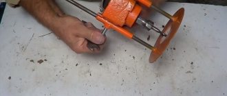
The use of an electric drill chuck will allow you to significantly modify the engineering solution. A shaft is clamped in it, the end of which must be pointed.
AUTOMATED ELECTRIC DRIVE OF THE MECHANISM FOR MOVEMENT OF THE ROD WITH A STEAMING MILL
Alyona
August 7, 2020
- 0
767
The diploma project briefly outlines the features of the technological process for producing pipes using a pipe rolling unit. The power calculation and selection of the motor for the automated electric drive of the mechanism for moving the rod with the mandrel of the piercing mill, and the calculation of the position controller were carried out. The mathematical model of the power section has been calculated
Automation, electronics / Machine tools
Convenient turntable
All that remains is to make a tool rest, where needle files, jigsaws, sandpaper, planes and hacksaws will be laid out during work. Its outlines are not regulated in any way, but it must be completely comfortable.
It is better to design such a table with the participation of the master who will become the main user of the automatic sharpener.
The best option is a swivel stand in the shape of a trapezoid. It is cut out of a thick iron sheet, after which it is mounted on a rotary hinge with a large two-way angle. It will be easy to move such a table in order to bring files closer to you or move them away for a while.
Personal experience
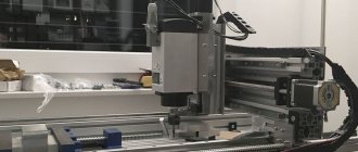
When I first started developing, thinking through and making the first CNC router with my own hands, it took about one day to create the project. Then, when I started buying parts, I did some research. And I found some information in various sources and forums, which led to new questions:
- Do I really need ball screws, or will regular studs and nuts work just fine?
- Which linear bearing is best and can I afford it?
- What motor parameters do I need, and is it better to use a stepper or a servo drive?
- Does the body material deform too much when the machine size is large?
- And so on.
Fortunately, I was able to answer some of the questions thanks to my engineering and technical background left after my studies. However, many of the problems I would encounter could not be calculated. I just needed someone with practical experience and information on the subject.
Of course, I received many answers to my questions from different people, many of which contradicted each other. Then I had to do more research to figure out which answers were worthwhile and which were garbage.
Every time I had a question that I didn't know the answer to, I had to repeat the same process. By and large, this is due to the fact that I had a limited budget and wanted to take the best that my money could buy. This is the same situation for many people who create a homemade CNC milling machine.
Cutters of different calibers
Cutting attachments are sold in every major hardware supermarket. At the same time, it is possible to buy both single cutting parts and sets.
With a wide selection of cutters available, the turner will create any complex and intricate configurations, including
- Grooves;
- Chamfers;
- Cones;
- Dashed lines;
- Edging;
- Wavy lines.
Grinder grinding machine
rustik427
October 21, 2020
- 0
1 600
Parts drawings + 3d model. Tabletop grinder for processing metal, plastic and wood products. Machine for working with sanding belts.
Machines / KOMPAS-3D
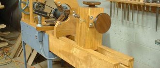
Photo of a homemade lathe
Dimensions and drawings
When determining the dimensions of the machine, first of all, we focus on the maximum length and diameter of the parts being processed. Let us recall that in industry, low-power turning equipment has the following boundary parameters:
- length - up to 1150 mm;
- width - up to 620 mm;
- the distance from the top surface of the bed to the spindle axis (axis height) is about 180 mm.
It is hardly worth exceeding these values on homemade equipment. We must not forget that with increasing size the danger of bending the geometry of the machine increases many times over. When choosing the size of the support and determining the extreme points of its movement, calculating the distance between centers and the limits of movement of the tool holder, it is best to focus on the drawings of home-made machines. Made by folk craftsmen, they have proven their performance in practice, so it would be stupid not to use proven solutions.
Tailstock Drawing of the support and tool holder Drawing of the bed Drawing of the headstock Homemade lathe. General view Drawing of the tailstock
Principle of operation
Perhaps the most important element on this machine is the milling cutter, engraver or spindle. It depends on your choice. If you have a spindle, then the tail of the cutter, which has a collet for fastening, will be tightly attached to the collet chuck.
The chuck itself is directly mounted on the spindle shaft. The cutting part of the cutter is selected based on the selected material. An electric motor, which is located on a moving carriage, rotates the spindle with a cutter, which allows processing the surface of the material. Stepper motors are controlled by a controller, to which commands are sent from a computer program.
electronics operate directly on the computer software that must be supplied with the ordered electronics. The program transmits commands in the form of G codes to the controller. Thus, these codes are stored in the controller’s RAM.
After selecting a processing program on the machine (finishing, roughing, three-dimensional), commands are distributed to stepper motors, after which the surface of the material is processed.
Advice: Before starting work, you need to test the machine using a specialized program and run a test part to make sure the CNC is working correctly.