How to make a homemade metal milling machine
Many do-it-yourselfers dream of getting a variety of tools and devices in their arsenal, and especially a homemade milling machine for metal processing.
Such multifunctional equipment makes it possible to engage not only in the processing of metal products, but also wood. Such units have been used in the industrial sector for a very long time. Naturally, industrial machines are complex and multifunctional products, but a homemade milling device also allows you to perform many manipulations in the processing of metal and wood. If you have all the necessary tools and consumables, you can make such a device yourself, and quite quickly. The simplest unit is considered to be a vertical milling machine, assembled from improvised and, most importantly, inexpensive materials.
Making a fixture for a stationary router
You can make cutters for the machine yourself. To do this, you need to prepare a cylindrical blank. Half the diameter is cut off on it in the area where the cutting zone is formed. The transition that appears is smoothed out. Next, another quarter of the diameter is removed, and the border is smoothed. The processed area of the workpiece is given a rectangular appearance by cutting off the lower part. As a result, the thickness of the metal in the working area should be 3–5 mm. Operations are carried out using a grinder or drill with an attachment, and sharpening of the edge is carried out on a sharpening machine.
It is recommended to sharpen the cutter at an angle of 7–9 degrees. Using diamond-coated files, you can give the edge any desired shape. When making a milling cutter of complex shape, the workpiece is flattened and bent.
Copy ring
CNC turning and milling machine for metal.
types and rating of the best In some cases, the copy sleeve is installed in one movement; in this case, alignment is not required.
There are other additional devices, but more on them later. Now let's talk about the copy ring - one of the mandatory attributes of a manual router, almost always included in the package. The device is very simple, but easy to use and useful.
Typically, this is a stamped steel plate with a raised ring around the center hole, which serves as a stop that tracks the copy template. The sleeve is selected for a specific cutter. Ideally, it should pass through the central hole with a small gap. In other words, you should not rely on the only ring that comes with the tool.
Most often, the bushing needs to be centered using a special cone. It is inserted into the collet (all the way to the copy ring), thereby leveling the position, and only then the mounting screws are finally tightened. Sometimes quick-release clamps are used instead of the latter, then there is no need to center anything.
The principle of operation of the equipment is simple - the protruding ring side in the center is guided along the template. In this case, the cutter follows the bends on the workpiece. The main “disadvantage” of such a “device” is one - it is impossible to get an exact copy - it will always be larger than the original.
This method is convenient in mass production (naturally, we are talking about household scales) or when the workpiece is valuable enough and it is worth making a template for its processing.
For precise and comfortable work, the router must have a smooth sole. When the copy sleeve is not in use, the groove intended for it is closed with a ring.
For precise and comfortable work, the router must have a smooth sole. When the copy sleeve is not in use, the groove intended for it is closed with a ring.
A similar bushing with the required diameter of the support ring is screwed on, but the mounting screws are not tightened.
For precise positioning of the bushing, a centering body is installed. It is clamped into a collet like a regular cutter (with the only difference being that the support sole is pressed against the body).
After installing the cone, the lowering mechanism stopper is released, and the sole, under the action of lifting springs, presses the cone to the bushing, thereby accurately centering it. Having secured the stopper again, the bushing fastening screws are securely tightened.
It is recommended to select a ring with the smallest possible diameter of the central hole, not forgetting that the working part of the cutter should pass through it freely.
If the template provides reliable support for only one side of the platform, an additional “support” is pulled out on the other and secured with a locking screw. If you don't do this, there is a high risk of losing exactly.
General operating rules
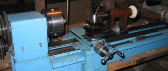
When working on a lathe, following safety precautions is the key to comfortable work.
Necessary:
- Always securely secure the workpiece before starting work, and then remove the key, if present.
- Remove all jewelry, especially chains or earrings. Tuck long hair under your overalls. Anything that may become wrapped around the product cylinder must be securely removed from the machine.
Important: Do not carry objects over a running machine. Any little thing can fall on the product and not only ruin it, but also bounce off in an unexpected direction.
How to make a machine for metal?
How to make a wood milling machine with your own hands
When milling metal, high stress and vibration occur. The wooden frame will not support them. It is necessary to use a cast iron plate and a metal profile made of low carbon steel.
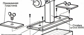
Option #1
The machine consists of:
- base;
- rack;
- slides with transverse movement guides;
- work table moving in the longitudinal direction;
- spindle head;
- stand with vertical guides;
- electric motor
https://youtube.com/watch?v=u2rbbCkZZnA
The cast iron base is leveled. A transverse dovetail groove is cut into it. A stand under the spindle carriage is attached to the rear part. The slide is inserted into a longitudinal groove. They move in the transverse direction due to the rotation of the screw. Ready made from a lathe will do. A table is installed on top. It moves along the figured slide guides. The tool moves vertically along with the carriage along the guides of the rack. A spindle head is installed on a massive plate in front, and a motor is mounted on the side. Both units are connected by a belt drive.
Option No. 2
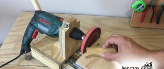
Using an electric drill as a milling head, you can create a simple and lightweight model of a vertical milling machine.
- Make a base in the form of a frame from a profile pipe.
- Place a slide with a screw on it for longitudinal movement.
- A tool holder from a lathe with a cross screw and a vice are installed on top.
- There are 2 stands attached to the base. They are connected by 3 cross members for rigidity. The bottom one is at the base. The top 2 serve as support for the spindle carriage.
The drill moves vertically along the carriage guides. A rectangular metal profile is used to manufacture the machine. All connections are made with bolts. Due to 2 racks, the design is stable and durable.
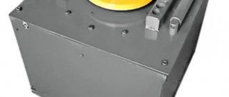
Milling cutter from a washing machine engine
Very often, craftsmen make various machines from a washing machine engine: wood lathes, drilling, sharpening, circular, as well as stationary milling machines. To make the latter, you will first need to make a table using the method described above. Next, you need to install a collet on the motor shaft to clamp the cutters.
Since it will not be possible to attach it to the motor shaft without an adapter, you will have to order one from a turner.
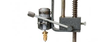
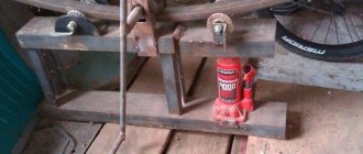
You will also need to make a lifting mechanism for convenient adjustment of the tool reach. It is made from two pipes that act as stands on which the engine is mounted, and a threaded rod.
One end of the pin enters the nut fixed to the bottom of the table, and the other rests against the lower part of the motor. A swivel wheel is rigidly fixed to the stud, with the help of which the height is adjusted.
To prevent dust from getting on the motor when the machine is operating, you can place a small piece of foam rubber on top of the motor.
Cutter with support bearing
The most elementary and compact device that sets the position of the machine is the cutter itself, if it is supplemented with a miniature ball bearing. It is located under or above the cutting knives and, accordingly, rests on the upper or lower edge of the edge. With the help of such equipment, shaped edges are obtained or grooves are cut for a connection, edging, seal, etc.
The advantages of the method include the ease of preparatory operations (you only need to adjust the vertical position) and the ability to accurately process rounded and curved edges (a typical example is a tabletop). The disadvantages follow from the advantages - it will not be possible to make a curve straight.
Pros and cons of homemade products compared to factory versions
Like every unit, a homemade machine has its advantages and disadvantages. The main one is the cost, which is several times lower in comparison with the factory version. In addition, the advantages of a homemade machine include:
- various manufacturing options . Each of the craftsmen can select the necessary drawing and make a machine that will fully satisfy his requirements;
- energy saving . Homemade machines, as a rule, are equipped with small, low-power electric motors, which can significantly reduce energy consumption.
The disadvantages include the lower accuracy of setting the milling depth compared to factory ones.
How to make a wood lathe with your own hands: drawings and technology
The easiest way to make a tool yourself at home is to construct a lathe or milling machine from a drill or electric motor removed from another tool. This process is not that complicated, so every master can handle it. To do this, you will need an electric motor, the power of which does not exceed 500 W, and available materials. A drill can also be used as a drive. Of course, making a lathe will require some skill.
The device of the tailstock of a homemade wood lathe
To build the machine, the following elements are required:
- metal frame;
- electric motor;
- handyman;
- tailstock.
It wouldn’t hurt to get a drawing that will help you navigate the dimensions and correctly manufacture all the structural elements for its subsequent assembly.
How to make a homemade drilling machine with your own hands with a motor
First you need to prepare the electric motor shaft. To do this, a faceplate is installed on it; a steel center with a thread is also suitable. Installation of the second center is carried out in the tailstock tube. To make the frame, you will need a pair of corners measuring 5x3 cm, their length is 15 cm. A motor is attached to the frame using a bolted connection.
An example of a homemade drilling machine
At the next stage of making a homemade machine, you assemble the headstock yourself. This element is formed from a pair of horizontal and a pair of vertical corners. A pipe intended for the spindle is attached to it. You need to insert a bolt into it, the diameter of which is 1.2 cm. First, its head is sharpened at a right angle. Thus, the central part of the spindle is designated. After this, the headstock is installed on the bed. On the top post, which connects to the horizontal corners, it is necessary to secure the tube by welding.
To make a tool rest, you need to take a steel rod with a chamfer. This element must also have a hole that will be used to secure the support ruler. It is necessary to vertically weld the tube with the locking screw to the long angle. Then the tool rest rod is inserted into it.
The motor rotor on which the faceplate is attached will be used as the headstock spindle. You need to make several holes in it. A fork will be inserted in the central part. The holes along the edges are intended for fixing the part with screws.
Even with the help of simple tools you can create interesting wooden products; for this you need to study the technology of working with the tool and practice
How to make a wood lathe from a drill with your own hands
Having a workbench with a strong and flat working surface at hand, you can build a lathe without resorting to building a bed. The electric drill in this case will serve as a rotary drive and headstock. According to the simplest drawing of the machine, it is enough to fix this tool on the surface of the workbench through the neck. Clamps and a clamp are suitable for fixing.
Next you need to make a stop that will act as a tailstock.
This element is mounted opposite the drill. To create it, you can take two blocks of wood and an adjusting screw, sharpened at one end to a cone. If you intend to use the machine for processing massive wooden workpieces, then it is advisable to fix the stop on the table using clamps.
To make a tool with your own hands, inexpensive materials are enough. A drill-based lathe can be used to turn various parts:
- door handles;
- structural details of the staircase;
- decorative items, etc.
Using a workbench with a durable and flat working surface, you can make a lathe from a drill with your own hands
To expand the functionality of the tool, its design can be supplemented with attachments and other devices that can improve the quality of work.
Such improvements include:
- winding on transformers;
- applying a coloring composition over a rotating part to create patterns;
- applying spiral notches to the workpiece, etc.
Installing a special attachment in the form of a copier will allow you to use the machine to create a whole series of identical parts or products according to a template.
An example of a multifunctional homemade woodworking machine from a drill
This is interesting: Drill for a hammer drill - choice of impact-cutting attachment, its purpose
How to make a router from a grinder?
The first version of the router that we will consider is made from an angle grinder. First, we will provide a list of materials and tools that will be required to create it, and then directly the instructions for its manufacture.
Tools and materials
If we talk about materials and tools, you will need:
- small angle grinder with a 125 mm wheel;
- a pair of discs – stripping and trimming;
- vice;
- emulsion coolant;
- chalk;
- M14 type tap;
- a piece of sheet iron that is about 1.5 millimeters thick;
- a piece of I-beam 18 cm with a length of 200-250 millimeters or a sheet of iron 5 mm thick;
- a pair of elongated nuts, as well as a pair of regular nuts that have a diameter of 8 millimeters;
- a pair of bolts with characteristics 8 by 40 mm;
- drills 0.8 and 1 centimeter;
- a pair of bolts 8 by 10 mm;
- cord brush for an angle grinder that has metal bristles;
- drill chuck with a threaded connection measuring 1.5-13 millimeters;
- a round crown with a diameter of 4 centimeters for making holes;
- a pair of clamping bolts equipped with wings measuring 8 by 20 mm;
- a pair of 8mm nuts;
- 10 centimeters of square pipe 2.5 by 2.5 centimeters, as well as half a meter of profile 2 by 2 centimeters.
In addition, you will need drawings of the device. They can be found on the Internet or in specialized literature.
Step by step diagram
So, in order to make a manual wood router, we will first need to make a sole for it. To do this, you will need to take an iron sheet of 5 mm thickness to ensure the rigidity of the future structure, you will need to cut a piece measuring 12 centimeters, then clamp it in a vice and sand it well with a cord brush. Then all that remains is to place the plate using chalk according to a pre-created pattern.
Then, in a vice, you should carefully cut out the metal using a cutting-off disc, without going beyond the intended contours. To bring everything according to the markings, you should use a cleaning disk. After this, the part will be ready. It will be the basis of everything.
- Now you need to make a mount for the grinder itself. To do this, use a crown to make a hole with a 4-centimeter diameter in the remaining part of the metal plate. This can be done using a hammer drill, having first switched it to drilling mode.
- The metal here itself is thick, and in order to avoid seating of the crown, you should add emulsion coolant, which consists of oil and water, from time to time. The part itself should be held with a clamp. The work should be carried out on a wooden base. The result should be a thick puck with an even hole and even margins.
- After this, you should create a base for attaching the angle grinder to the previously created part. You just need to cut off unnecessary parts and treat it with an abrasive material. Now you need to adjust the hole to the part of the grinder gear motor, which is stationary and protrudes slightly. This will be the basis of the fastening.
- The spare part needs a little modification by cutting off the protrusions. After this, you should start creating brackets so that the tool can move upward. To do this, you will need prepared square-shaped pipe parts. The big one will move along the smaller one. And pipes measuring 20 by 20 will act as guides.
- Now you need to cut a pair of thin tubes 2 by 2 centimeters with a length of 30 centimeters on a cutting machine so that the chuck, where there is a long cutter, will fit, as well as sufficient distance to adjust the height. As a sled, we will have a pair of pipes 2.5 by 2.5 centimeters with a 4-centimeter length. In one you will need to make a hole with a diameter of 1 centimeter and weld an 8 mm nut. After this, when tightening the bolt, the slide will be locked with a wing bolt equipped with a guide pipe.
Now on the tacks you should create a structure from:
- pairs of guides 2 by 2 centimeters;
- pairs of slides 2.5 by 2.5 centimeters;
- designs for fastening to the angle grinder gearbox.
Carefully weld the guide brackets, attaching them tightly to the above-mentioned sole. Here you cannot overheat the metal of the tube, otherwise free movement of the slide will be impossible. After this, you should firmly weld the angle grinder clamp to a pair of pipe sections that will be required for vertical movement.
But this clamp will work normally only after creating a clamp.
It can be done as follows.
- A 5mm gap should be made in the middle.
- On one side of the resulting arc, we weld an elongated type nut, and on the other, a simple one. A thinner nut should be pre-drilled with a large drill so that the bolt moves freely. This is best done by first clamping the structure in a vice. After this, the bolt that is tightened will firmly fix the angle grinder to the protruding area of the gearbox in a vertical position. At this point, the part that is responsible for moving the tool is ready. True, some devices come without a gearbox, which are based on other devices.
- After this, you need to prepare the mounting ears for the hole in the gear housing. They are made of thin metal, the thickness of which will be no more than one and a half millimeters. An elongated oval is drawn with a marker, where a hole is made for the bolt on one side. The parts should be bent diagonally in a vice by gently tapping with a hammer. The lower part of the eyelet is welded to the created clamp, and the upper part should be screwed to the gear housing. The main part of our router is ready. Now the nozzle or chuck must be attached, after which all that remains is to assemble the product and configure it.
- The cartridge should be the simplest one. The diameter of the clamped router or drill will depend on the power of the angle grinder motor, as well as the tasks that are planned to be implemented. Any option that has a clamp spread in the range of 1.5 - 13 millimeters will be sufficient. The only important point to pay attention to is the threaded cartridge fit.
With a high degree of probability, neither the thread pitch nor the diameter of the hole will coincide with similar moments on the angle grinder. Then you will need to take an M14 tap, and then screw on a pressure washer. It remains to make sure that there is no play, which means that the pitch matches.
All that remains is to cut the thread and screw the cartridge onto the grinder spindle. This resulted in a finished product for attaching the cutter.
Now all that remains is to assemble. To do this, you must first paint and dry all the components. The finished parts are assembled onto the angle grinder, firmly clamp the gearbox into the mounts:
- We put the fasteners on the gear head, after which it should be screwed tightly;
- then it should be connected with bolts with fastening for rigidity;
- we install the cutter in the chuck, and then fasten it firmly;
- we mount the base and put on the tool with the slide;
- We adjust the height using tools and bolts on the slide.
That is, we have a reliable and high-performance homemade milling cutter made from an angle grinder.
Cutting aluminum and how to get good results
Balance: A metal milling machine with a high feed rate and a very shallow depth per pass allows for good cooling of the cutter. It will pass through the aluminum alloy workpiece quickly enough to cool itself, but if the tool lingers too long (slow feed and deep depth per pass) in the same place, it will heat up and melt the cut on the workpiece due to friction. Keep in mind that almost any type of CNC router can successfully cut aluminum.
Consider this analogy: an adult can dig a hole quite quickly and shovel large amounts of sand at a time. A child can dig sand too, but only scratch the surface over and over again, and not take a full shovel. A child will eventually reach the same depth as an adult, but it will take a little longer.
Problem: A child does not use a shovel most effectively because the sharp tip of the shovel will dull faster than the top of the shovel, whereas an adult will work evenly with the entire shovel. The same is true with end mills. The deeper you can go through the workpiece with a router bit, the more evenly it will wear, extending its life.
So, what parameters must be met? This is an important question, because the result can cost a pretty penny. We have a good example. As already written above, a compact CNC metal milling machine and a vortex system are used to blow air through the cutter at a temperature of -50 degrees
The material being cut is grade 6061, which is a structural grade of aluminum, and its thickness is 5 mm, but it does not matter, since the cutting is carried out with a large number of passes. The thicker the material, the longer it will take to process, however, this is already clear
A Chinese spindle with a speed of 13,000 rpm is used for cutting. The feed rate (the speed at which the end mill moves through the cut) is set between 300 and 430 mm/min. Depth per pass is an important parameter that should be selected carefully. Onsrud, which has extensive experience in the face milling industry, recommends that the depth per pass be 1/2 the diameter of the cutter's cutter. For a 3 mm end mill, this is about 1.5 mm, but for finishing it is still better to take a depth equal to a quarter of the diameter of the cutting tool.
When cutting metal, vibration of the workpiece is the main problem that needs to be eliminated. At home, you can use a variety of fixation methods, ranging from clamps to a special vacuum table. No matter what clamping or clamping method is used, make sure that it will not move at all and that the clamp (screws, clamp) is as close to the cut as possible.
Let's sum it up
Based on the above, we can highlight the following points, remembering which it will become much easier to mill metal:
- Take your time. It’s better to spend more time on processing than to waste a mountain of expensive tools and ruin more than one workpiece.
- Use carbide cutters. They will serve for a very long time with correctly selected cutting conditions. And it is advisable to buy cutters from trusted manufacturers and in specialized stores.
- Use cutters with a smaller diameter. It is better to make more passes and get a beautiful cut place than to remove a kilogram of aluminum in one cut, throw away the “burnt” tool and see the torn edges of the workpiece.
- Don't be paranoid about cleaning the cut areas. There is no need to stand with a brush or vacuum cleaner over the workpiece you are processing; at the end, it is enough to simply sweep away all the waste or collect it with a magnet (if it is a ferromagnetic material).
- Lubricate the working tool with a mist of coolant. The “fog” effect is achieved by using a special fitting on the liquid supply pipe.
- Don't slow down the feed too much. If the feed is too slow, the cutter, instead of cutting the material, begins to rub against it and heat up very much, which leads to overheating of the tool and melting of the cut site (if the workpiece is made of a low-melting material).
- If your metal cutting machines do not feed fast enough, use fewer passes and increase the diameter of the cutter.
Installing the headstock and tailstock
One of the most important parts of the machine is the headstock and tailstock. The workpiece is clamped between them. The headstock directly rotates the product.
Important!
To make the base of the headstock - the spindle shaft - you need to turn to professional metal turners or find a finished part or generally ready-made headstock modules in specialized stores.
The design of the front tank consists of two bearings of type S, V or U, which are bolted to the frame of a shaft machined from carbon steel with a diameter of 40 mm, a chuck for clamping the part.
The shaft is equipped with three or four pins that help eliminate vibration. The shaft is passed through the bearing and pins are attached to it with a key or other fastener for cylindrical parts, after which the shaft is fixed on the second bearing, which is already tightly bolted to the steel corners or the board of the frame.
The tailstock also produces rotational movements, but does not set the product in motion. It is especially important to fix the tailstock on the same axis as the front one, because all subsequent work will depend on this.
Reference. For subsequent control of the axis, the headstock can be designed with adjustment screws, which will allow slight changes in the axis of rotation of the headstock.
The tailstock consists of the following elements:
- A base of angle steel or similar material, similar to the base of a headstock.
- Guide pipe.
- Inner tube or quill. It is made in such a way that it can be placed in a guide pipe, and then a drive screw can be passed through the quill.
- Drive screw. A screw with a nut thread for the quill tube. An 8 mm thread is provided for mounting the flywheel on the rear.
Required Tools
A very dense piece of cast iron or stainless steel is used to make the frame. A special shaft is attached to the caliper from above. Its upper zone rises above the table through an opening. In all such machines, the shaft lift height can be adjusted.
A spindle equipped with a cutting tool is mounted on top. Industrial models use a solid cutting arsenal. The key types of equipment are: disk, knife and cutters of various shapes.
To carry out cutting strictly along a straight vector, a special guide bar is used. Due to a special fastening unit, it moves to the desired length. The quality of processing increases significantly if the dynamics of spindle rotation is high.
Selecting materials for the router
The following materials are recommended for the manufacture of a copy router:
- knee cemented polished shaft with a diameter of 16 mm;
- linear bearings – 2 pcs.;
- guide rails 90 cm long – 2 pcs.;
- rectangular pipe 30 x 60 mm and 40 x 40 mm with a wall thickness of no more than 3 mm;
- metal plate 90 x 10 cm;
- end posts – 2 pcs.;
- rocker arm for attaching the copier and cutter – 2 pcs.;
- movable coupling – 2 pcs.;
- crown type coupling for turning the part and the template.
The dimensions of all elements are specified when developing a detailed drawing.
The operating principle of wood milling machines
Equipment in this category is intended for creating wood products. The technology is reminiscent of the work of a sculptor cutting off unnecessary parts of a shapeless blank. In this case, the main functions are performed by the cutter. This tool with sharp edges rotates at high speed, which speeds up work operations. It is driven by an electric motor. To ensure the required precision of movement, specialized mechanical devices are used.
Schematic diagram and kinematics
The drawing shows the design of a professional category machine. This example is suitable for studying typical functional components:
- To ensure precise manual movement of workpieces, special rulers (1, 5) and a multi-position sector (2) with teeth are used. These parts are fixed on the table (17).
- The limiter (4) prevents foreign objects from entering the work area.
- The remote control (6) is placed at a convenient access distance. The emergency power switch and other controls are placed here.
- The cutter (3) is installed on the spindle (12). It is reinforced with an additional upper support (7), which is inserted into the bracket (8). To lift this unit there is a special flywheel (9).
- The tension of the belt drive is adjusted using a handle (10) with a screw drive.
- The electric motor (11) is located at the bottom. The massive frame ensures stability in all operating modes.
- A separate flywheel (13) changes the height of the spindle. The switch (15) sets its rotation speed.
- The main switch (16) is installed on the side wall.
This design is designed for heavy loads. It is suitable for creating metalworking equipment. In this publication we are talking about wood milling machines, so it is permissible to use a less durable power frame and electric drives of relatively low power.
The cutter is installed in the spindle in the upward direction, the drive is in the lower part of the housing
This design with a wide and durable table is well suited for face processing of large workpieces. Work operations are performed manually, so rulers and other limiters are useful.
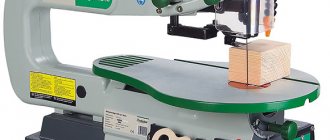
Vertical milling machine for wood (factory model)
This option ensures higher processing accuracy with the help of rigid fixation of the workpiece and built-in smooth movement mechanisms.
CNC wood router
This is the most expensive equipment with improved technical characteristics. Here, the spindle for a wood router moves along with the tool along a given path very accurately using stepper motors without intervention or careful control by the user. Ensures high processing speed without compromising quality. An additional advantage is the possibility of repeating the same technological processes many times.
Copy horizontal wood milling machine
In this design, the working unit is rigidly connected to the control probe, which limits its movement taking into account the shape of the sample. Using this not too complicated device, you can create high-quality copies in your home workshop.
For your information! If necessary, you can find instructions for creating homemade turning and milling machines for wood and other modifications. In any case, it is necessary to determine in advance the characteristics of future technological operations to clarify the parameters of suitable equipment.
What is a CNC machine?
The first software products used in machine tools were developed back in 1804 - these were punched cards with binary code. Further, fist-type mechanisms came to replace them, which ensured smooth operation of the mechanisms, but lost in the simplicity of developing algorithms. The first numerically controlled electric motor machine was developed by Personson, and its industrial use began in 1949 - the unit was used for stamping parts for aircraft.
In the vastness of the Soviet space, the first CNC device was the 1K62PU screw-cutting lathe. The development of the equipment dates back to the second half of the 60s. Since 1980, the build-up of automated machine tools has increased dramatically around the world, and in 2022 you can see an incredible surge in this field of activity.
1) The concept of a CNC machine and the advantages of the technological solution
The direction is not easy to understand, therefore, before directly developing a CNC metal milling machine with your own hands, it is necessary to study a certain theoretical basis.
CNC is an analogue of two foreign abbreviations:
- NC (Numerical control).
The progenitor of modern control systems. It is based on control of operation through rigid circuits (plugs, switches, and so on). Algorithms are stored on external media, and there is no RAM as such;
- CNC (Computer numerical control).
Current equipment control systems that use specialized software to operate. The most important elements of systems in the hardware aspect are controllers and processors.
At cereal factories, work takes place according to the model of an automated workstation, where work programs are transmitted to equipment via a local/global network. Modern CNC machines can increase the speed of work by 3-5 times compared to manual production of parts.
Important: modern CNC equipment operates in two interrelated areas - CAD and CAM. The first system is responsible for the design, and the second for its direct production.
CNC equipment is a mechanism that produces a new part by subtracting excess from the workpiece. Some also include 3D printers in this direction, but such devices can only indirectly be called machine tools, because they create parts from scratch.
Advantages of CNC equipment:
- Minimizing the influence of the human factor on the equipment operation process.
- The speed, smoothness and direction are set in advance, and there are very few failures in the operation of such programs.
- No marking operations are required.
- Simple operation and reconfiguration of algorithms for different types of parts.
- High speed.
- The minimum volumes of defects are the wrong size, breaks, and so on.
- Efficiency in performing diverse types of tasks.
- Regularity in time allows you to plan production and predict the timing of orders in advance.
Although CNC machines have a lot of positive qualities, you should not neglect the shortcomings of the equipment - high cost, imperfect software and narrow focus on processes. CNC machines are good for mass processing, but for unique elements, this approach will not work.
The table below will tell you about the components of modern CNC devices. Having studied the components in detail, creating a CNC machine with your own hands on metal in the future will be much easier than doing everything at random using primitive drawings from the Internet.
| Knot | Component Tasks |
| Workpiece processing software | Algorithm of actions for the machine hardware in encoded form. The program performs the functions of turning on or off other components of the system + forces them to process the part according to the previously specified instructions, consisting of Latin letters and numbers. |
| Input device | For PC hardware connoisseurs, this point is easy to understand. For advanced CNCs, data entry was carried out from the keyboard. In less prosperous factories, reading equipment based on magnetic tape or punched paper is used. |
| Control device | Central CNC unit. Here, signals from the input device are decoded, axis interpolations + their motion patterns are implemented, speed is adjusted, and other auxiliary tasks are launched that are available in the machine system. |
| Drive unit | The assembly includes amplifier circuits, ball screw type transmissions + the motor itself. Thanks to amplification of signals from the control system, the machine quickly puts into operation mechanisms for adjusting the position of moving equipment components. |
| gun | Most machines have a standard processing set - a table, a working head with a processing tool that can move along 1, 2 or 3 axes, depending on the model of the CNC machine. |
| Measuring system | All kinds of sensors that record data in real time. The information received is compared with the parameters specified in the program, and if the data does not match, the control system adjusts the values to the required ones - speed, angle, immersion depth, etc. |
Thanks to a pre-developed work algorithm, the human factor influencing work is minimized. The role of humans in modern CNC machines is the operator and maintenance personnel. When controlling, this means pressing a couple of buttons and turning the unit on/off from the outlet. Maintenance + repair is much more difficult - this is already done by specialized specialists.
2) Classification of CNC machines + areas of application of equipment
Such equipment is designed to process any type of raw material - from plastic to durable steel grades.
Depending on the selected material of the parts to be processed, the equipment should be divided into 5 categories. Distribution of machines by type of processing:
- drilling The mechanism is based on a drill, which, due to a rotational movement, makes holes of the required diameter, or “slides” the workpiece to obtain irregular shapes;
- turning Here the object itself is already rotating along/counterclockwise or at a certain angle. The drill head remains motionless;
- milling The cutting attachments of the heads help to get rid of unnecessary materials from the workpiece and give it the required shape;
- chemical/electrical. A special direction in processing, where specialized technologies for cutting metals are used. For example, EDM ultrasonic or photochemical processing;
- others. This includes all technologies that do not fit into the above - laser processing machines, oxygen cutting, and so on.
2 options for assembling a metal lathe with your own hands
More often than others in everyday use (although CNC machines themselves are a curiosity in everyday life), milling cutters and units for processing soft metals or wood are used. The table below will tell you more about the classification of CNC machine tools.
| Classification parameter | Components | Description |
| Movement | Spot | For operation of the equipment, fixation of both the part and the implement is required. Such machines are called units with position processing. The CNC controls the transitions from point to point. |
| Contour | Here the workpiece remains in a fixed position, and the processing element moves along a given path. Hardware control provides for 2 axes of movement simultaneously, and the position of the head and the workpiece must be constantly monitored. | |
| Control system | Open | The operating algorithm is supplied by the operator through a peripheral input device. The information is converted into impulses, which, with the help of servo amplifiers, drive the machine components into action. The disadvantage of such CNCs is the lack of feedback, which does not allow extremely precise control of the operation of the system in general. |
| Closed | There is a feedback system, which increases the accuracy of the machine. About 90% of CNC systems in production operate on this principle. | |
| Axles | 2-axis | An example is lathes. Movement occurs along each of the axes at an angle of 90 degrees. |
| 3-axis | Movement along the X/Y/Z axes. | |
| 4-axis | One of the axes is a rotating mechanism | |
| 5-axis | 4-axis + one more axis - this is a multi-position rotary table. | |
| Drive unit | Hydraulic | The advantages are ultra-precision and smoothness with power, but such machines are an order of magnitude more difficult to maintain than their analogues. |
| Electrical | Servomotors with AC or DC current. Their advantage is their compactness and ease of management. The best option for a do-it-yourself CNC metal milling machine. | |
| Pneumatic | The working substance is compressed air. Such drives are relatively inexpensive + simple in design and fire safety. Disadvantages: low power, noise and lower positioning accuracy. |
When starting a manufacturing business, machine tools with software are an expensive but correct solution. Increased purchasing/maintenance costs are offset by labor savings. Instead of 10 people, production will require 2-3 operators.
Homemade router: option No. 1
In fact, this model is a combination of a lathe and a drilling machine. From the first one the bed will be used. A coordinate table is installed on the guides, which will move along one axis. A support column is mounted in place of the headstock to install the milling head.
The electric motor is mounted separately so that its vibration does not affect the accuracy of operations. A tensioner is required at the top of the milling head. It is used to adjust the belt drive.
Features of self-production of a milling machine:
- the working head is shifted in the vertical plane using a worm gear;
- plate for installing workpieces with fastening grooves;
- installation of a lighting device to increase the accuracy of the work performed.
Using this milling machine, you can perform basic operations on processing metal workpieces. The disadvantage of the design is the lack of a rotating mechanism on the working head.
Selection of manufacturing scheme
First you need to decide on the type of operations to be performed. Additionally, the maximum size of the workpieces, their weight and configuration are taken into account. For home use, it is recommended to make a desktop milling machine. It will be mounted on a homemade or factory frame.
Processing occurs due to the displacement of the working head relative to the workpiece. The optimal scheme is to change the height and tilt of the milling machine and move the work table along the X and Y coordinate axes.
To implement this you will need the following components:
- Bed. It is designed for installation of equipment and stability of the machine.
- Milling head with electric drive. It must be a factory model with a Morse taper.
- Electric motor for driving the head. Optimal power is up to 500 W.
- Transmission. For home use, you can use a belt circuit.
- Control unit - switch and fuses.
Making a machine entirely from scrap materials is labor-intensive and time-consuming. You can use factory components that ensure good technical characteristics and reliable operation of the equipment.