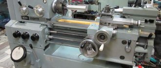
A stripping and grinding machine is a special device that provides stripping and cleaning of castings in industrial conditions. In home workshops, such devices are practically not used. They remove excess layer from metal workpieces: rolling, stamping. In this case, the formation of products does not occur.
The effectiveness of how the grinder will work depends on the speed of rotation of the grinding wheel. It is also important to choose the correct force for the impact of the abrasive material. There are different types of devices presented, but you need to choose them correctly, taking into account many factors.
Stationary machine
The category of stationary roughening and grinding machines is represented by single- and double-sided units. The technique is used mainly when processing small castings. Stationary type devices are represented by radial sharpening machines and face grinding machines.
The former are in much greater demand due to their versatility. Such machines are usually equipped with abrasive wheels, the diameter of which varies from 400 to 750 millimeters. Their grinding intensity range ranges from 4-50 meters per second.
Hanging machine
The overhead roughing and grinding machine is used for processing medium and large sized metal castings. A special feature of these machines is that they are suspended, which makes it possible to rotate the massive structure in a vertical plane around its axis, as well as lift and lower it without applying significant effort.
Suspended machines are distinguished by the high power of built-in electrical units, as well as the large dimensions of the abrasive wheel. Of course, with such a “set” the labor productivity of the master is quite high.
Special machines
This category of grinding and grinding machines includes a variety of automatic and semi-automatic units. All of them are involved in the casting processing process. Moreover, such devices are used mainly in mass production.
In special machines, most of the work is done automatically. The craftsman only needs to install the rough casting, and then remove the finished processed product.
Today, the grinding equipment market is saturated with a variety of equipment models. We will dwell in detail on the 3M636 roughing and grinding machine - one of the most popular units in the post-Soviet space.
Standard device structure
The 3M636 grinding machine has several main components that work harmoniously with each other. The design of a roughing and grinding machine is not complicated.
Head with two-speed electric motor. Thanks to it, the movement of abrasive wheels is ensured. The shaft is housed in a housing with two covers. Its ends are equipped with bearing units, which simultaneously support the spindle.
Spindle supports - the presented unit ensures the reliability of the equipment and the accuracy of rotation of the wheels. The supports contain seals.
Cooling unit - the operation of the electric motor is accompanied by the release of a large amount of heat, which can lead to breakdown. Therefore, the device must be cooled during operation. This is accomplished due to air flows located in the cavity of the housing and inside the frame. They circulate constantly, they have no obstacles.
Head covers - protective covers are attached to them. Additionally, it is allowed to fix devices for polishing workpieces on them.
Grinding machine head covers
Bed - most often it is made of cast iron. Inside the frame there is a cabinet in which all electrical equipment is hidden. In the front part there is a window that gives access to all internal components of the equipment. During operation, it is securely closed with a lid.
Transparent protective screens. They protect against metal dust and make work more convenient. A lamp is adopted as an additional device.
Replacing the grinding wheels is quick, because to do this you just need to fold back the side of the casing.
The design of the device is quite simple, so some craftsmen are able to build the device themselves. However, in the household there is no need for a stationary option, since at home you will not have to process hundreds of workpieces every day.
Model features
This tool is designed for cleaning and roughing castings in a production workshop. Thanks to its worthy performance characteristics, it has gained popularity in the market and has become the standard of reliability and performance.
In terms of accuracy class, this unit complies with the “H” standard, which means that the equipment is excellent for finishing work. This machine is equipped with two 600mm 75mm wide grinding wheels, which are driven by a powerful 7kW power motor. The rotation speed of grinding wheels ranges from 955-1425 rpm. In this case, the distance between the centers of the circles is 1025 millimeters.
The 3M636 roughing and grinding machine is capable of processing fairly large products. The maximum workpiece weight reaches 30 kg, which is enough to perform most tasks encountered in a foundry. The device is equipped with a small desktop 110x200 mm. At the same time, the dimensions of the machine itself are 1275x750x1350 millimeters, and the weight is 860 kg. Of course, with such parameters, transporting equipment from one workshop to another will cause a lot of trouble, which must be taken into account when purchasing.
Results
Nowadays, a craftsman should not have any problems choosing a suitable roughing and grinding machine. The market offers a wide range of different special, stationary or suspended units. Those who are limited by budget can be advised to pay attention to used Soviet equipment, such as the 3M636 model. If you are interested in more innovative machine tools, it makes sense to choose among European and Asian machines, which are superior to domestic engineering solutions in many respects.
Equipment Specifications
The main technical operational parameters are described in detail in the equipment passport. However, it is not always possible to purchase it, since the grinding and roughening model 3K634 is no longer available.
This equipment can be used for cutters with various types of cutting edges, the height of which does not exceed 100mm. Using a support table, drills with a diameter of 6 to 60 mm are sharpened. Processing of metalwork tools in various ways, possibly chamfering or polishing parts. But before each of these operations, you should select the right grinding wheels and select the optimal operating mode of the machine.
Model specifications:
- circle dimensions: height – 50 mm; diameter – 400 mm; landing diameter – 203 mm;
- the height of the centers from the base is 90 cm;
- for sharpening cutters, a height of 6 to 100 mm is recommended;
- Drill sharpening is carried out at the following values of the tool tip degree - from 70 to 140. In this case, the clearance angle should be 20°;
- installation of a 300 cm sanding belt is possible;
- polishing wheel dimensions: diameter – 40 cm; maximum height – 55 mm; hole diameter – 50 mm;
- electric motor power is 4 kW;
- spindle characteristics. Cutting speed, m/s – 30. Rotation speed, 1/min – 1440;
- machine dimensions – 100*68*123 cm with a weight of 358 kg.
These characteristics allow the 3K634 model to be used in small-scale production and when performing repair work. To ensure maximum operating efficiency, a dust collector is located at the bottom of the equipment.
To sharpen drills, use a special attachment. It is not included as standard. It can be purchased separately or made independently, based on the actual characteristics of the equipment.
Grinding and grinding machine model 3M634
The roughing and grinding model 3M634 is intended for roughing, casting and sharpening of tools and grinding of workpieces.
Sharpening machine 3K634
Technical characteristics of this roughing model:
- The diameter of the grinding wheels is 40 cm.
- The width of the rings is 4 cm.
- Table dimensions - 15x8 cm.
- The distance between the circular centers is 70 cm.
- The largest weight of the processed product is 20 kg.
The 3M634 machine is equipped with a three-phase electric motor and is controlled by an irreversible magnetic starter type MPKO - 110.
Download the passport of the 3M634 roughing and grinding machine
Some recommendations for using 3M634:
- grinding wheels must be stored, tested and handled in accordance with the manufacturer's instructions;
- the demolition of the rings should not be different;
- the table must be secured securely upon completion of the next rearrangement;
- Only an instructed person can install the circles;
- rings and flanges should be inspected before installation;
- The casing is periodically cleaned from abrasive dust.
Technical data and characteristics of the 3E711B machine
| Parameter name | 3G71 | 3E711V |
| Main settings | ||
| Accuracy class according to GOST 8-82 | IN | IN |
| The largest dimensions of processed products (length x width x height), mm | 630 x 200 x 320 | 630 x 200 x 375 |
| The greatest height of the processed products with the largest diameter of the grinding wheel, mm | 325 | |
| Maximum height of workpieces with smallest grinding wheel diameter, mm | 375 | |
| Distance from the spindle axis to the table mirror, mm | 80…445 | 500 |
| Maximum mass of processed products, kg | 220 | |
| Accuracy parameters maximally achieved on the sample product | ||
| Product sample size, mm | 380 x 120 x 80 | |
| flatness, µm | 4 | |
| parallelism, µm | 5 | |
| roughness of the surface processed by the periphery of the grinding wheel, Ra | 0,16 | |
| Perpendicularity of the trajectory of the transverse movement of the table to the direction of its longitudinal movement, µm | 25 | |
| Machine work table | ||
| Dimensions of the working surface of the table (length x width), mm | 630 x 200 | 630 x 200 |
| Maximum manual longitudinal movement of the table, mm | 710 | 700 |
| Speed of longitudinal movement of the table (stepless regulation), m/min | 5..20 | 2..35 |
| Table movement per revolution of the flywheel of the longitudinal movement mechanism, mm | 15,3 | |
| Table support. Table cross feed mechanism | ||
| Maximum manual lateral movement of the table / automatic, mm | 235 | 250/ 245 |
| Price for dividing the flywheel dial for transverse movement of the table, mm | 0,05 | |
| Price for dividing the micrometric feed dial for transverse movement of the table, mm | 0,01 | |
| Automatic cross feed for each table stroke (stepless regulation), mm | 0,3…4,2 | 0,3..30 |
| Accelerated movement of the table cross support, m/min | 1,5 | |
| Grinding head. Grinding wheel | ||
| Maximum vertical movement of the grinding head, mm | 365 | |
| Accelerated vertical movement of the grinding head, m/min | 0,27 | |
| Grinding wheel dimensions, mm | 250 x 32 x 76 | 250 x 40 x 76 |
| Grinding wheel revolutions per minute | 2740 | |
| Highest cutting speed, m/s | 35 | |
| Dividing value of the vertical movement flywheel dial, mm | 0,001 | 0,002 |
| Fine vertical feed dial division price, mm | 0,0005 | |
| Automatic feed of vertical movement (stepped in increments of 0.005), mm | 0,005…0,05 | – |
| Automatic feed of vertical movement (stepped in increments of 0.002), mm | – | 0,08..0,002 |
| Electrical equipment and machine drive | ||
| Number of electric motors on the machine | 5 | 7 |
| Grinding wheel spindle drive electric motor, kW | 2,2 | 4 M1 |
| Electric motor for table hydraulic drive, kW | 1,1 | 3.0 M2 |
| Electric motor of the oil cooling fan in the hydraulic station, kW | – | 0.09 M3 |
| Cross feed drive electric motor, kW | – | 0.18 M11 |
| Electric motor for accelerated movement of the grinding head, kW/rpm | 0,18 | 0.55 M8 |
| Cooling pump electric motor, kW/rpm | 0,125 | 0.15 M6 |
| Magnetic separator electric motor included with the unit, kW | 0,08 | 0.12 M7 |
| Total installed power of all electric motors, kW | 3,685 | 8,09 |
| type of supply current | 50Hz, 380/220V | 50Hz, 380V |
| Dimensions and weight of the machine | ||
| Machine dimensions (length x width x height), mm | 1870 x 1550 x 1980 | 2000 x 1770 x 1920 |
| Machine weight, kg | 2000 | 2550 |
Bibliography:
Surface grinding machines 3E711VF1, 3E711AF1, 3E711V, 3E721VF1-1, 3E721AF1-1, 3E721V-1, 3E711V-1, 3E710A. Operating manual, 1978 Surface grinding machine 3E711B. Manual. Electrical equipment, 1983
Alperovich T.A., Konstantinov K.N., Shapiro A.Ya. Design of grinding machines, 1989
Alperovich T.A., Konstantinov K.N., Shapiro A.Ya. Setup and operation of grinding machines, 1989
Dibner L.G., Tsofin E.E. Sharpening machines and semi-automatic machines, 1978
Genis B.M., Doctor L.Sh., Tergan V.S. Grinding on cylindrical grinding machines, 1965
Kashchuk V.A., Vereshchagin A.B. Grinder's Handbook, 1988
Kulikov S.I. Honing, 1973
Lisova A.I. Design, adjustment and operation of metal-cutting machines, 1971
Loskutov V.V. Metal grinding, 1985
Loskutov V.V. Grinding machines, 1988
Lurie G.B. Grinding machines and their adjustment, 1972
Lurie G.B. Design of grinding machines, 1983
Menitsky I.D. Universal sharpening machines, 1968
Mutsyanko V.I. Bratchikov A.Ya. Centerless grinding, 1986
Naerman M.S., Naerman Ya.M. Guide for training grinders. Textbook for vocational schools, 1989
Popov S.A. Grinding work, 1987
Tergan V.S. Grinding on cylindrical grinding machines, 1972
Shamov B.P. Types and designs of main components of grinding machines, 1965
Related Links. Additional Information
Home About the company News Articles Price list Contacts Reference information Download passport Interesting video KPO woodworking machines Manufacturers
Grinding and grinding machine 3M636
On the market you can find a variety of offers of grinding equipment. But the 3M636 machine is the most common.
Double-sided sharpening machine 3M636
3M636 is designed for cleaning and roughening parts in industrial environments. Its excellent performance has resulted in high market demand. It is called a standard that confirms reliability.
In terms of class accuracy, this equipment is classified as standard “H”, and this becomes evidence that the described technique is used for the final finishing option. This machine was equipped with a pair of 60-centimeter grinding discs with a width of 7.5 cm. They are driven by a seven-kilowatt powerful motor. Grinding discs of version 3M636 rotate at speeds from 950 -1420 rpm. The distance between their centers is 102.5 cm.
3M636 machines can process fairly large castings. The maximum weight of a part can be 30 kg. This is quite enough to complete all the tasks that need to be solved in foundry production.
Technical characteristics of 3M636 equipment
The 3M363 grinding machine is a domestic device used for professional metal processing. It has the following technical characteristics:
| Options | Indicators |
| Accuracy class | N (suitable for finishing work) |
| Grinding wheel dimensions (diameter) | 60 cm |
| Abrasive tool width | 7.5 cm |
| Number of grinding wheels | 2 |
| Distance between circle centers | 102.5 cm |
| Distance from the floor to the middle of the abrasive element | 85 cm |
| Maximum workpiece weight | 30 kg |
| Abrasive wheel rotation speed | 955–1425 rpm |
| Table dimensions | 11×20 cm |
| Main drive power | 7 kW |
| Machine dimensions | 127.5×75×135 cm |
| Unit weight | 860 kg |
Purpose of the 3M636 grinding machine
The 3M636 roughing and grinding machine is produced by a Russian machine-building enterprise and is designed to remove the defective layer of material from workpieces on castings, forgings, rolling, stamping and welding workpieces. In this case, the surfaces of the workpieces are cleaned without shaping them.
In terms of accuracy class, the 3M636 roughing and grinding machine complies with the “H” standard, which means that the equipment is excellent for finishing work. This machine is equipped with two 600mm grinding wheels with a width of 75mm, which are driven by a powerful 11kW power motor. The rotation speed of grinding wheels ranges from 955-1425 rpm. In this case, the distance between the centers of the circles is 1025 millimeters.
The 3M636 peeling machine is capable of processing fairly large products. The maximum weight of the workpiece reaches 30 kg, which is enough to perform most of the tasks encountered in a foundry. The unit is equipped with a workbench (worktable) measuring 240x380 mm.
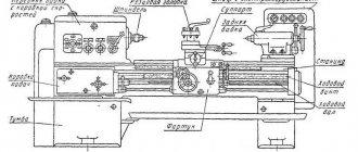
Layout of the main parts of the 3M636 machine
b) - rear view (casing 8 not shown)
List of main parts of the 3M636 roughing machine
- Frame
- Bearing shell
- Brackets for hand rests
- Protective cover
- Grinding wheel
- Lighting lamp
- Helpers
- Protective cover with handles
- Outlet pipe
- Motor mounting plate
- Drive pulley
- Shaft
- Control Panel
- Electrical cabinet
- Brackets for protective screens
- Transparent protective screens
Description of the design of the 3M636 sharpening and grinding machine
On the upper part of the machine body 1 there are bearing housings 2 and a protective casing 8 with handles. The bearings support the shaft 12 on which the drive pulley 11 is mounted. The pulley 11 has the ability to move axially along the drive shaft 12 of the machine. Rotation of the pulley 11 is transmitted by V-belts from an electric motor located inside the housing 1 and fixed to the plate 10. Auxiliary installation movements of the electric motor are made along the horizontal grooves of the plate 10. The belt tension can be adjusted using the vertical grooves of the plate 10. Protective covers 4 are attached to the bearing housings 2 with outlet pipes 9. Inside the casings 4, grinding wheels 5 are fixed on the shaft 12. The brackets 3 are supports for the tool rests, which can be installed at the height required by the operator. The presence of grooves in the hand rests 7 allows you to move them to the desired position.
Protective transparent screens 16 are installed on the brackets 15. The machine operates only with the protective screens 16 lowered.
For stripping (cleaning) cast iron and steel castings, medium-hard (ST2) and hard (T) wheels with a grain size of 20 and 24 units are used. The permissible rotation speed of the wheel when cleaning castings is determined by the peripheral speed in the range of 40-50 m/sec.
The 3M636 machine is intended for operation in UHL climatic conditions for placement category 4 according to GOST 15150. The ambient air temperature in working conditions must be at least 5°C, relative humidity 45÷80%. Illumination of the workplace is not lower than 200 lux. Atmospheric pressure 630÷800 mm Hg. Art.. The time of day is not regulated.
We offer to buy a 3M636 roughing and grinding machine at the manufacturer's price.
Kinematic diagram of surface grinding machine 3B722
Kinematic diagram of surface grinding machine 3B722
Vertical feed chain of the grinding headstock
Manual feed. The movement from flywheel 35 is transmitted through gears 23, 22, clutch 21, bevel gear pair 20, 19 to nut 18 connected to lead screw IX..
Since the nut is fixed against vertical movement, when it rotates, screw IX will move in the axial direction and move the carriage with the grinding headstock.
Automatic feeding. At the moment of reversing the grinding head, oil is supplied to one or another cavity of the cylinder of the feed mechanism 46 and moves the plunger rack 47. The latter, through the gear 48, rotates the crank 45, which, through the connecting rod 44, turns the lever 43 with the pawl 37 sitting on it at an angle of 40-50° .
The pawl turns the ratchet 25 connected to the flywheel 35. The movement is then transmitted along the chain described above to the screw.
The amount of automatic feed is adjusted by turning the cover 24, as a result of which the pawl 37 can turn the ratchet 25 along the entire path of its movement or part of it. The position of the cover 24 is changed from the handle 30 through gears 28, 27, 29, 26 and a gear sector cut on the cover 24.
To automatically stop the feed after removing the set allowance, a sector 31, 88 mounted on the limb 36 is used. At the same time, it enters the rolling zone of the pawl 37, which begins to slide along it without touching the teeth of the ratchet 25.
When working manually, a hard stop 38 is brought to the “hard stop” by the handle 39, against which at the end of the stroke the stop mounted on the dial 32 rests. The dial is connected to the flywheel 35 by means of a gear lock 33, which is activated by pressing the button 34.
Accelerated movement. An accelerated installation movement is prepared by turning the handle 41. In this case, using a helical groove on the shaft using a lever 49, gear 22 is disengaged from gear 23 and flywheel 35 is disconnected from the feed chain. At the same time, the cam 40 presses the limit switch 42, which unlocks the push-button station for starting the electric motor of the rapid movement mechanism.
When the electric motor is turned on, the movement from the electric motor shaft is transmitted by a silent chain through sprockets 52, 53. Gears 50, 51 to screw IX along the previously discussed chain.
In this case, the grinding head moves up or down.
Grinding headstock cross feed chain
Manual feed. From flywheel 12 through a worm gear (worm 5 - gear 4), rotation is transmitted to rack and pinion gear 2, which is meshed with rack I mounted on the grinding headstock.
To prevent the transmission from breaking when the grinding head is hydraulically moved from the cylinder, worm 5 is disengaged from gear 4 by turning handle II. In this case, the eccentric sleeve is blocked by cam 6 and lever 3, excluding the movement of the grinding head from the hydraulic cylinder when the worm is turned on.
Automatic feeding. When the grinding headstock moves transversely from the hydraulic cylinder, pin 17, mounted on the headstock body, slides along the spiral groove of shaft III, causing it to rotate. Next, through gears 16 and 15, a disk with adjustable stops 13 is driven into rotation. The disk with stops makes almost a full revolution at the maximum transverse passage of the grinding headstock, and the stops, acting on the reversible handle 14, rotate it together with the roller and the lever 9 sitting on it. The lever with one of its fingers acts (when reversing the grinding headstock) alternately on the limit switches 7 and 10, which give the command for vertical automatic feed, and with the other finger it switches lever 8, connected to the reversing spool of the grinding headstock reverse hydraulic box.
Handle 14 can also be used to manually reverse the grinding headstock.
Grinding head drive. The grinding wheel spindle receives rotational motion through a coupling from a flange-mounted electric motor with a power of 10 kW at 1460 rpm.
Scope of application of roughing and grinding machines
Rough grinding
used to remove defective layers of material from workpieces on castings, forgings, rolling, stamping and welding workpieces. In this case, the surfaces of the workpieces are cleaned without shaping them.
To increase the efficiency of rough grinding, a sharp increase in the volume of metal removed per unit time is used at high operating speeds, longitudinal feed rates and high clamping forces in the processing zone. This makes it possible to reduce the overall allowances for mechanical processing of heat-treated workpieces of increased hardness, and in some cases eliminate milling, planing, and fire cleaning when removing allowances of up to 10 mm or more per pass. This method of high-speed rough grinding is widely used in mechanical engineering when processing workpieces by grinding without preliminary turning, in the metallurgical and foundry industries when preparing and finishing rolled products, and cleaning castings. With this method of rough grinding, a line of special rough grinding machines is used, operating at an operating speed of 60-80 m/s, a longitudinal feed speed of up to 60 m/min, a clamping force of 6000-10000 N, and a main drive power of 75-160 kW. To operate on these machines, hot-pressed grinding wheels with outer diameters of 500, 600 and 800 mm are produced from zirconium electrocorundum with grain sizes of 160, 200 and 250.
The effectiveness of casting processing depends on the speed of action of the abrasive tool and the forces with which the abrasive tool acts on the surface of the casting. The higher the cutting speed and force, the more efficient the machining process. Processing efficiency is measured by the amount of metal removed from the casting per unit of time (usually per minute). The higher quality the casting is made, i.e., the fewer fills, tides and burns it has, the less labor intensive the processing of rough rough grinding.
For stripping (cleaning) cast iron and steel castings, medium-hard (ST2) and hard (T) wheels with a grain size of 20 and 24 units are used. The permissible rotation speed of the wheel when cleaning castings is determined by the peripheral speed in the range of 40-50 m/sec.
Roughing and grinding machines for processing castings are divided into portable or hand-held mechanized tools, stationary, suspended and special.
Setting up the machine when sharpening cutters
Sharpening cutters on back surfaces
When sharpening cutters along the rear surfaces, it is necessary to loosen the screw securing the support in the curved guides and set the rear angle along the dial, tighten the screw securing the support (Fig. 14. a).
Set the protractor at an angle of 90° - φ (φ is the main angle in the plan) or φ1 (auxiliary angle in the plan) (Fig. 14, b, c, d) and secure the protractor so that the middle of the sharpened edge coincides with the middle of the diamond ring circle. It is necessary to ensure that the length of the section where the cutter rests on the protractor bar is as long as possible. After this, the assistant is given a rocking motion (oscillation). The amount of oscillation is set by the stops of the oscillating tool rest.
The cutter should not be allowed to come off the diamond ring of the grinding wheel.
The set of accessories includes devices for sharpening the back surfaces with a cutter clamp and a protractor without a clamping device. When working without a clamp, the cutter is fed to the wheel by moving the cutter along the support bar of the protractor; when working with a clamp, the flywheel is rotated. It should be borne in mind that at angles φ and 90° - φ less than 45°, it is better to use a device with a cutter clamp.
Sharpening cutters along the radius
The radius is sharpened manually, and oscillation of the table is not required.
When sharpening straight cutters along the front surface, the work is carried out in a device for sharpening the rear surfaces with a mechanical clamp (Fig. 14, e), but the cutter must be laid on the table with the side plane of the holder and the base of the holder pressed against the reference ruler of the dial.
The required front angle of the cutter is set using the protractor, and the inclination angle is determined using the tilt dial of the tool rest.
Sharpening is done by oscillating the tool rest, and feeding is done by rotating the cross-feed handwheel.
Sharpening bent cutters along the front surface
When a device for sharpening the front surfaces is installed on the tool rest, it is an inclined tool rest (Fig. 14, e).
The device is fixed at an angle. A device for sharpening the rear surfaces is secured in the groove of the tool rest, aligning the “0” of the protractor with the edge of the groove. The rest of the settings and work are carried out in the same way as when sharpening straight cutters on the front surface. The creation of thresholds on the front surface of the cutter is similar. The circle for this purpose must be profiled according to the shape of the transition part of the sill.
Finishing of cutters
The finishing of the cutters is carried out with a finishing diamond wheel in the same way as sharpening. Recommended modes when working with coolant - transverse feed for 10 double strokes of the table, mm:
- pre-sharpening: 0.1..0.2
- finishing sharpening: 0.03..0.06
- finishing: 0.01..0.02
Longitudinal feed is independent, carried out by springs within the range of 1..4 m/min.
When feeding manually, there should be a cutter pressure on the wheel of 7..12 kgf/cm2 (when sharpening a cutter with a sharpening strip of 10 x 2 mm, the pressing force is 2..2.5 kgf).
Cooling
Grinding, sharpening and finishing with diamond wheels should be done with cooling.
The use of coolant during the grinding process increases the durability of diamond wheels and reduces the wear rate of diamond grains.
The coolant reduces the heating temperature of the workpiece (tool) and reduces local stresses that can lead to cracks and chips. In addition, the coolant removes grinding waste from the working surface of the wheel, which helps to significantly reduce the “greasing” of the wheel surface, increase the cleanliness of the machined surface by one or two classes, increase productivity by 25..30% and reduce the wear rate of the wheel by up to 50%.
When using metal-bonded wheels, cooling is mandatory (except for shaped finishing) and must be continuous. Coolant should be supplied in an amount of 2 - 3 l/min. Organic bonded wheels can be used without cooling,
Coolant splash protection
The protective casing of diamond wheels is made with a reversible flap, and a disk is placed in the circle to prevent intense splashing of coolant.
It is necessary to ensure that the damper, when working with cooling, completely covers the non-working area of the grinding wheel.
To protect against the jet of coolant knocked off by the cutter, there is one shield with a permanent magnet on each side of the machine, mounted on the tool rest or on the cutter holder. In addition, shields installed on the edge of the trough prevent splashes from hitting the floor of a working machine and provide protection for the worker.