Short description
The design provides for mechanical feeding of the tool on the machine. This has a positive effect on productivity and makes operation easy. The processing depth is controlled visually (vernier scale) or set by a travel limiter.
The hole processing work performed on the 2A135 vertical drilling machine can be divided according to the type of processing:
- Roughing: drilling (blind, through);
- reaming;
- boring;
- countersinking;
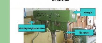
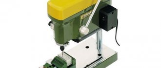
General view of the drilling machine 2A135
Machine 2A135 - front view
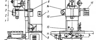
Vertical drilling machine 2A135 - side view
Retrofitting with additional units and devices made it possible to use the machine in large-scale and mass production.
Purpose of the device and scope of its use
The 2A135 vertical drilling unit is designed to perform a wide range of operations:
- countersinking;
- opening holes;
- countersinking;
- cutting blank ends;
- cutting with threaded taps.
Performing a wide range of work allows the unit to be classified as a universal device. This device is not intended for mass production and is not used in industrial enterprises that produce a wide range of products. The use of the machine is limited to small-scale production of single products.
The equipment is ideal for repair departments of factories and tool shops. Subject to improvements in the design, the unit can be used for mass production of products.
The machine belongs to the fourth placement group. The device is equipped with cutting tools made of three main types of material:
- high alloy steels;
- high-speed steels;
- high hardness alloys.
The unit has a relatively small work table. For this reason, small-sized parts are processed on it. Suitable products for machining are:
- cast iron parts;
- blanks from different types of steel;
- parts made of non-ferrous metals.
Processing parts on a machine
Specifications
The technological capabilities and performance characteristics of the 2A135 vertical drilling machine are shown in the design parameters:
Basic data
- accuracy class according to GOST 8-71 – N (normal);
- maximum resulting hole size, mm: steel 45 – 35;
- cast iron – 45;
- the largest - 1130;
Table
- mounting plate WxD – 450x500;
- vertical table travel – 325;
- T-shaped grooves, quantity – 3.
Headstock
- landing cone for the tool in the spindle - Morse 4 according to GOST 24644-81;
- number of revolution speeds – 9;
- installation speeds: 68 rpm;
- 100 rpm;
- 140 rpm;
- 195 rpm;
- 175 rpm;
- 400rpm;
- 530 rpm;
- 750 rpm;
- 1100 rpm;
Parameters of electrical elements
- supply current - three-phase, alternating;
- power of electric motors: main - 4500 W;
- coolant stations (X14-22M) - 125 W.
Dimensions
- overall dimensions of the machine, LxWxH - 1240x810x2500 mm;
- assembled equipment weight - 1.3 tons.
Where is the 2r135f2 CNC drilling machine used?
The machine in question is used to regulate the process of rectangular machining and positioning. The program carrier is a punched paper tape with eight tracks. The machine is equipped with a digital display; up to 15 adjustments per tool length can be entered.
The machine has a closed system in which the BS155A selsyn acts as sensors. The table and slide are positioned with an accuracy of up to 0.02 mm, digital display and movement assignments have a resolution of up to 0.01 mm. There are a total of 3 controllable coordinates, 2 of which can be used simultaneously.
Design
The 2A135 vertical drilling machine does not have any highly complex units in its design. Nevertheless, the innovative ideas of that time laid down such a margin of safety that it still amazes us.
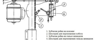
Main components of the vertical drilling machine 2A135
- Table base plate;
- Desktop;
- spindle unit;
- spindle head or gearbox;
- spindle head;
- electric drive;
- steering wheel;
- stand (bed);
- handle for raising and lowering the work table.
Operation and repair
The operation of the device begins with its column, which performs the function of fixing it on the floor surface. The column is made of cast iron. The work table, which is attached to the column, moves together with the drilling head using a manual drive.
The movement occurs along the column itself. The plate, which plays the role of the base, has an internal cavity in which a special cooling liquid is located. A sump tank is also installed there. An electric pump system is attached to the upper part of the base plate, with the help of which, during operation of the machine, coolant is supplied to the workpieces.
The feed box is installed separately in a special housing located in the working head.
The second main technique for operating the 2n135 machine involves operating the feeder. It includes the following elements:
- 2 couplings, one of which is ratcheting, the other is overrunning;
- steering wheel for control;
- rack-and-pinion gear located on a horizontal shaft;
- worm-gear;
- limba having divisions.
Limba
Thanks to the feed device, the scheme of working with the machine implies a wide range of actions:
- switching off, switching on feed;
- cutting threads on the product itself using the manual feed method;
- spindle retraction upwards from the workpiece;
- bringing the processing tool to the product manually;
- performing advance feed manually.
The mechanism works as follows: the jaw clutch is driven by a rotating handwheel. The clutch then drives a gear, which is connected to a rack, which feeds the spindle.
All this is done manually. When the processing tool impacts the workpiece, the gear rotates. Movement occurs along the axis of the shaft until the moment when the cams of the coupling itself are opposite each other. At this moment the clutch turns 2000.
In cases where the machine was repaired, it is necessary to check its components
It is important to ensure that there are no traces of corrosion on the device. After repair work, the unit runs idle, and the cutting tool is not installed
During a test run, the operation of the device is checked against the data in its technical passport.
Node design
The main load of the 2A135 vertical drilling machine is carried by a column and a slab. But thanks to the housing design and large mass, loads and vibrations are dampened, and rigidity increases.
Spindle
The spindle unit is a rigid structure, therefore, to increase the processing accuracy, precision bearings are installed in it. Its design allows you to perform the following actions:
- turning on the approach after performing a quick approach (automatically);
- turning off the supply upon reaching the set processing depth;
- manual movement is carried out by the steering wheel;
- The steering wheel is equipped with an automatic drive activation device.
Spindle assembly of vertical drilling machine 2A135
Cooling
The cooling system for the tool and workpiece is similar to those installed on other vertical drilling machines. The container is the internal cavity of the mounting plate. A pump is mounted on it, and along the body there is a distribution of pipelines with taps that regulate the supply of coolant.
Cooling system design for vertical drilling machine 2A135
Gearbox and feeds
The combined gearbox and feeds form all the working movements of the machine. The main, main movement is the circular rotation of the spindle with the working tool. The rotation from the electric motor is transferred to the gearbox via a belt drive. On the spindle, rotation at a given speed is generated by two sets of gear blocks.
Auxiliary movement – movement of the tool. Rotation is removed from the shaft that transmits rotation to the spindle. The selection of feed and its activation is carried out by clutches. According to the diagram, 12 speeds are possible, but due to the fact that two are combined, the result is 11.
The device of the gearbox of the drilling machine 2A135
The spindle head has manual movement to increase the distance between the table plane and the end of the spindle. This allows you to install large parts. Rotation of the handle sets in motion a gear that moves along a rack. This moves the spindle head.
Engine and gearbox design
The drilling unit has design features.
The machine spindle is fixed in supports using precision bearings, which ensures smooth and accurate drilling of products.
The same device is responsible for turning on and off feeds and quickly moving the spindle, which significantly saves time on additional operations.
The cutting tool is fed automatically immediately after it is brought to the surface of the product. The machine table moves horizontally during operation.
The vertical drilling machine is equipped with a special stopping mechanism with a stop, with the help of which the feed of the cutting tool is switched off automatically when the desired drilling depth is reached.
The unit provides the possibility of replacing the drive pulleys that are part of the V-belt drive.
Electrical equipment
The electrical diagram shows how individual working bodies are controlled on a 2A135 vertical drilling machine.
Power supply is carried out by turning on packet 4. The command device is push-button, with separate activation of electric motors. The power for lighting the work area is taken from one phase and passes through a transformer.
Electrical diagram of a vertical drilling machine 2A135
Functioning of components and assemblies
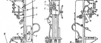
Kinematic diagram
The main movement of the machine is in the vertical direction. This is how the position of the head changes and the spindle moves quickly. The exception is the horizontal movement of the working surface of the table. To become familiar with the operating features of the equipment, it is recommended to study its kinematic diagram.
For vertical rotation of the spindle, the design of the machine includes an electric motor with a power of 4.5 kW. To interface these components and the ability to change the rotation speed, a gearbox and V-belt drive are installed. In this case, the maximum speed can reach 1070 rpm.
The feed movement is carried out from the spindle through a system of gears and gearboxes. The latter houses the sliding keys on the three- and four-stage mechanisms. This design allows you to select the optimal operating mode from 12 theoretical or 11 actual gear parameters. This difference is explained by the repetition of the parameters of the two gears.
To carry out the auxiliary movement, it is necessary to adjust the position of the handle P2. In this case, a rapid shift of the spindle is performed after changing the parameters of the steering wheel Ш.
Features of components and assemblies, their characteristics:
- Transmission. It consists of two mechanisms of a special shape, the design of which has retractable keys. They are necessary to prevent damage when shifting two gears at the same time;
- feed mechanism To activate it, a steering wheel is used, which has several degrees of freedom. The drive from the gearbox is via a dog clutch. There is a quick shutdown mechanism when activating feed in the forward and reverse directions relative to the workpiece.
Features of the electrical circuit of the 2A135 machine include built-in short circuit protection and an installed bracket for connection to the ground loop. To activate the reverse mode, you need to press the “right” button on the control unit. In this case, the upward reverse feed is activated.
To quickly stop the engine, you must move the handle to the middle position. One of the design flaws of the 2A135 machine is the lack of a mechanism for quickly deactivating the power unit.
Passport details
The list of supplied tools and equipment included with the machine, as well as electrical and mechanical drawings, contains a passport for the machine. There are also requirements for:
- installation;
- reconciliation;
- acceptance
The figure shows the dimensions of the foundation pad and installation dimensions.
Mounting dimensions of machine 2A135
The instruction manual contains information:
- about lubrication points;
- frequency of inspections and repairs;
- any malfunctions that have arisen and options for eliminating them;
- about the list of bearings;
- about materials used for the manufacture and repair of failed parts.
Download the passport (operating instructions) of the vertical drilling machine 2A135
Our advantages
The products try to meet any of your requests. Our machines solve all issues in the field of drilling materials. They are convenient and easy to maintain. Their quality has been tested over years of use. Prices are reasonable and affordable.
The machines are in demand both in Russia and in neighboring countries. We guarantee their uninterrupted operation for many years, and are ready to listen to your suggestions. The order is placed by our managers easily and quickly. Payment by any method available to you. We provide delivery to any of the specified regions.
Advantages and disadvantages
For 50 years, vertical drilling machines 2A135 have been operating in enterprise shops and workshops. This is facilitated by the safety margin laid down by Soviet designers. Modern models require expensive repairs after 5 years of active use.
The advantages include:
- Long service life.
- Price. Buying used equipment is much cheaper compared to modern analogues. In the event of a breakdown, the cost of parts and their production is not high. Available and inexpensive materials.
- Simple controls. The absence of electronic components allows you to work on the machine after an introductory training course.
Operating procedure on the machine
Setting up the machine for operation consists of installing the table and drilling head in the positions required for operation, clamping them on the column, and setting the required rotation speeds and spindle feeds.
The 2S132PF2I machine provides the following control modes:
- adjustment (manual control from buttons);
- automatic (control from DRO K524);
- semi-automatic (positioning of the table according to the program from the DRO device, and the approach and removal of the quill with the spindle manually).
To establish the adjustment mode, it is necessary to set the “Mode selection” switch on the machine control panel to the “Adjustment” position.
Working on the machine in the “Adjustment” mode is carried out by pressing the corresponding buttons on the control panel.
To select the movement axis, use the “Select X and Y axes” switch. To move the table in positive and negative directions, use the “Positive direction of movement” buttons, respectively. To control the direction of spindle rotation, use the “Spindle rotation to the left” buttons on the control panel.
To rotate the gears in the gearbox when switching spindle rotation speeds, use the “Spindle Rotation” button.
The 2S132TS machine provides the following control modes:
- manual mode;
- auto.
In manual mode, set the “Mode selection” switch to the middle position “Manual mode”. The machine is controlled by pressing the corresponding buttons on the machine console “Spindle rotation to the left”, “Stop”. The working feed is carried out both from the steering wheel and using a mechanical transmission from the main movement electric motor.
In automatic mode, set the “Mode selection” switch to the extreme left position “Drilling”. Set the cams depending on the processing depth. Using the steering wheel, move the spindle to the upper starting position. Press the “Start cycle” button.