To assemble a water level meter, I was faced with choosing a measurement method - contact or non-contact. Contact methods include resistive, capacitor and inductive methods; among non-contact methods, visual, radar and ultrasonic methods are most widespread. In order not to affect the quality of the water in the container, we will resort to one of the non-contact methods of measuring the liquid level.
All contactless methods are based on the same principle: the signal goes away, a certain time passes, the signal returns. The visual method uses an optical signal, it is quite accurate, but if the sensor becomes dirty, it will stop working altogether.
The radar level measurement method uses high-frequency radio wave signals, making the method not suitable for home use. The ultrasonic method is similar to radar, only ultrasonic waves are used instead of radio waves. This method suits us perfectly because ultrasonic sensors are easy to find and inexpensive.
I made a liquid level meter based on the Arduino Mega2560 microcontroller (you can take any Arduino controller).
The author of the article is not responsible for any damage received during the assembly process.
Advantages of a homemade LED sensor
The advantages of a do-it-yourself liquid level sensor made from “free” parts are the following:
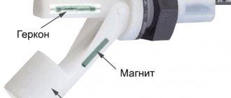
- High reliability. Thanks to the use of reed switches, which are electrical contacts hermetically sealed in a bulb, operation in conditions of high humidity does not negatively affect the efficiency of the device.
- Lightweight design. Due to the fact that almost all the elements used in the manufacture of a homemade sensor are plastic, they have minimal impact with their mass on the polymer pipe on which the device is mounted. Plastic is practically not subject to corrosion, which is also one of the most important advantages of the product.
Source freeseller.ru
- Almost all parts can be obtained free of charge. In my case, the pipe elements were left over after laying the sewer system, I soldered the LEDs from the old radio, and the reed switches were purchased earlier on Aliexpress for the purpose of making a contactless relay for switching the operating mode of the electric motor.
Do-it-yourself circuits for monitoring the water level in a tank may contain a larger number of reed switches. For example, if it is necessary to more accurately determine the liquid level in a tank, then a gradual light transition from blue to red from 5 to 7 parts can be used.
In this video, watch how best to choose a float for a septic tank full sensor:
Selection rules
Selecting a level gauge for tanks must take into account a large number of factors. Among them:
- water composition;
- the volume of the container and the material that was used to make it;
- the need to control the maximum and minimum liquid levels or monitor the actual condition;
- the possibility of introducing automatic control into the system;
- switching capabilities of the device.
To select household devices, it is important to consider the capacity volume, control circuit and operating principle.
Homemade float switch
If you have the time and desire, then you can make a simple float water level sensor with your own hands, and the costs for it will be minimal.
Mechanical system
In order to simplify the design as much as possible, we will use a ball valve (faucet) as a locking device. The smallest valves (half-inch or smaller) work well. This type of faucet has a handle that closes it. To convert it into a sensor, you need to extend this handle with a strip of metal. The strip is attached to the handle through holes drilled in it with the appropriate screws. The cross-section of this lever should be minimal, but it should not bend under the influence of the float. Its length is about 50 cm. The float is attached to the end of this lever.
use a two-liter plastic soda as a float The bottle is half filled with water.
You can check the operation of the system without installing it in the tank. To do this, install the faucet vertically and place the lever with the float in a horizontal position. If everything is done correctly, then under the influence of the mass of water in the bottles, the lever will begin to move down and take a vertical position, and the valve handle will turn with it. Now submerge the device in water. The bottle should float up and turn the valve handle.
Since valves vary in size and the amount of force required to switch them, the system may need to be adjusted. If the float cannot turn the valve, you can increase the length of the lever or take a larger bottle .
We mount the sensor in the container at the required level in a horizontal position, while in the vertical position of the float the valve should be open, and in the horizontal position it should be closed.
Electric type sensor
To make a sensor of this type yourself, in addition to the usual tools, you will need:
- Half-inch plastic pipe for soldering water pipes. The length of the pipe is arbitrary and depends on the size of your tank.
- Three-core copper wire with a wire cross-section of 0.5 mm2. The length of the wire is equal to the length of the tube plus the distance to the control unit to which the sensor will be connected.
- Polystyrene foam block 5*5*8 cm.
- Magnet. It’s good if it’s a ring one, for example, from an old speaker. Its internal diameter should be 4-6 mm larger than the outer diameter of the tube.
- Two reed switches. One is with a normally closed contact, the other is with a normally open contact.
- Soldering iron, solder and rosin.
The manufacturing sequence is as follows:
- We make a float from polystyrene foam. To do this, round the corners to make a cylinder. We drill a hole along the length 3 mm larger than the outer diameter of the pipe. We attach a magnet to one of the ends of the cylinder. You can attach it with epoxy glue or tighten it with threads. Make sure the magnet does not drown the float.
- We pick up the phone. We heat one of the ends and crush it so that a thickening is formed. This will prevent water from entering the pipe and at the same time will serve as a limiter for the lower position of the float.
- We put the float on the pipe with the magnet facing up and move it to the lower position. The float with the magnet must move freely along the pipe.
- Let's take the wire. Align its end with the lower end of the tube. We put the first mark in the place where the magnet is located. The lower level reed switch will be located here. The second label should correspond to the top one. Apply the same mark to the pipe. This will simplify installation and configuration of the system.
- We take a reed switch with a normally open contact and solder it to the wire at the lower level. To do this, we strip the insulation on the central core and on one of the side cores.
- A reed switch with a normally closed contact is installed at the upper level. We solder it to the central core (it is common to both reed switches) and to the remaining free one.
- At the lower end of the wire, the wires must be insulated from each other. On the other side, mark which wire is connected to what.
- We insert the wire with the reed switches into the pipe until it stops, and fix its upper end with sealant.
- We attach the finished sensor vertically inside the container, taking into account the mark of the upper position of the float. The tube has some buoyancy. To prevent it from floating up and becoming deformed, load its lower end.
When the liquid level changes, the float moves along with it, which acts on an electrical contact to control the water level in the tank. A control circuit with such a sensor may look like the one shown in the figure. Points 1, 2, 3 are the connection points for the wire that comes from our sensor. Point 2 is a common point.
Let's consider the principle of operation of a homemade device. Let's say that at the moment of switching on the tank is empty, the float is in the lower level position (LL), this contact closes and supplies power to the relay (P).
The relay operates and closes contacts P1 and P2. P1 is a self-locking contact. It is needed so that the relay does not turn off (the pump continues to work) when the water begins to rise and the contact of the low pressure unit opens. Contact P2 connects the pump (H) to the power source.
When the level rises to the upper value, the reed switch will operate and open its contact VU. The relay will be de-energized, it will open its contacts P1 and P2, and the pump will turn off.
As the amount of water in the tank decreases, the float will begin to fall, but until it takes the lower position and closes the NU contact, the pump will not turn on. When this happens, the work cycle will repeat again.
This is how a water level control float switch works.
During operation, it is necessary to periodically clean the pipe and float from dirt. Reed switches can withstand a huge number of switchings, so this sensor will last for many years.
Source: instrument.guru
Hi all. Today we will talk about a very simple kit for self-assembly of a device to control the water level. This set can be successfully soldered by a student in grades 5-7 in one evening. Of course, you can do it completely yourself, including the board, but I decided to save time, so I ordered a kit.
The set was purchased with the goal of somehow automating the collection of water into a barrel at the dacha. Moreover, this is not exactly a barrel, but rather a pipe going down 2.5-3 meters, so the water reserves there are decent (for simplicity, let there be a barrel). The idea was simple, while there is no regular water supply, the electric valve opens and fills the barrel with water at a given level. Consumption of water in buckets as needed and automatic refilling into the barrel. To ensure that the valve does not often operate due to water fluctuations, several levels are designed. The lower one at which the valve turns on and the upper one at which it turns off. Those. there is a certain dead zone in which there is water flow, but there is still no water supply to the barrel. By the way, this dead zone is actually such a thing as hysteresis
. Last year, this function was performed by such a sorry device as a float mechanism from the toilet cistern. It worked properly and occasionally became clogged, since the water comes through pipes straight from the river. But in the end, it didn’t survive the winter because it was made of plastic and fell apart from the frost. This set was intended to replace a failed mechanism.
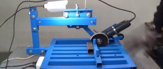
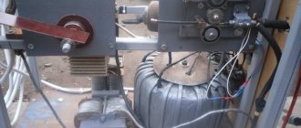
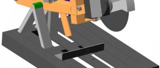
While storing the assembled board and waiting for the summer season, an attempt was made to use the assembled board in production, on this installation. This is just a large saucepan with a heating element type heater with a power of 27 kW. The products are taken out of the refrigerator in whole pallets and placed in a saucepan. It all needs to be heated to 90 C. Can you imagine how much electricity is wasted every day?!
The products, by the way, are pork stomachs and curly (part of the intestines). As far as I know, the stomachs are stuffed with something and eaten, and the intestines are roughly the same - including sausages.
This thing is cooked and re-frozen. Next it goes to China. This is the cycle of goods in nature. We give them natural by-products, and in return we give them electronics...
The question has arisen to switch the heating of the pan to steam. It's more economical and the power is higher. Productivity increases significantly. This is where a level sensor was needed so that no one would be scalded by the steam and steam would be supplied only when there was at least a minimal amount of water in the container.
However, I realized it in time and refused the final installation, although tests showed that the board was working. It is contraindicated to use homemade products in production. Therefore, we found a less quickly needed device that performs the same functions, but also has a certificate. The operating principle of the factory device practically corresponds to the set from the online store and, in a particular case, performs the same functions. This device is a domestic production Aries SAU-M7.
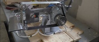
In a small bag there is a “bunch” of parts, a board and wires. I didn’t sort by denominations, I just laid them out for clarity. The scheme is not simple, but very simple. 4 2I-NOT elements are used, with two of them serving as a trigger. It is needed to form a hysteresis loop. Pins 1 and 2 of J3 provide a low level signal and turn on the relay. Contacts J4 1 and 2 are high level and emergency; when any of them is triggered, the relay turns off. The relay operation is duplicated by lighting the LED. The scheme works reliably on tap water and just as reliably on water after water treatment, which contains less salts. I assembled the board almost without looking at the diagram, except to look at the resistor values. It is unlikely that the pins will be mixed up, and even the installation of parts such as connectors or transistors will be prevented by the silk-screen printing. The only drawback during installation was that I mixed up the LEDs. But this is so, little things do not affect performance. Homemade conductometric type level sensors were used as sensors. This is roughly what they look like assembled:
On the side of the board where the parts are installed, there is silk-screen printing, which is quite high quality. The process of unsoldering parts will not be of interest to you, since I am not an assembler and do not know the specifics of the board assembly process. Whatever came into my hand from the edge, I soldered it. The printed circuit board is covered with a protective mask on the solder side. There is no metallization. The fee is one-sided.
I used solder type POS 61 with rosin. I screwed up a little. I fixed the power wires with sealant so that they would not break off at the exit from the holes. The wires that came with the kit seemed too short to me. I washed the board with a solvent and alcohol and covered it with a layer of Plastik 70. I immediately noticed the difference between my previous boards and this one. The surface is shiny and the contacts are covered with a layer of film. There was some inconvenience, which is actually a plus. I wanted to make a video about the operation of the board using a multimeter, but I got a problem in the form that the chips simply do not push through the protective coating. That's why there is no multimeter in the video.
Video demonstrating the board's operation:
Upd:
While I was writing the review, I didn’t even pay attention to the product page, as usual. And only after writing the review did I pay attention to the product. The board does not match the one that was sent to me and judging by the comments, many are sent two different versions of the board. This does not affect the functionality. Both boards are functional.
Results:
The simplest set, available for schoolchildren, also has practical applications. I recommend it for purchase. There was a slight residue left due to the fact that the board received was not the one in the description.
In my case, the wires turned out to be redundant. They were probably planned to output LEDs from the board to the front panel and connect a power source.
Source: mysku.ru
Principle of operation
The circuit diagram of a self-made water level switch is very simple. When the septic tank is not yet filled, the float is in the lower position, and the neodymium magnet is opposite the first reed switch. In this position, the reed switch contacts will be forcibly closed to pin 3, through which the electric current is directed to the green light bulb.
As soon as the tank is filled, but the liquid level has not yet reached critical values, the float will rise slightly and the effect of the magnetic field on the contacts of the first reed switch will stop. In this position, the “standby” mode will be activated, in which both reed switches will operate in a state where the current through them passes to contact 2.
After the liquid level in the tank rises, the float will move upward, and the neodymium magnet will align with the second reed switch, in which the contacts will switch to contact 3, through which electric current will flow to the red LED.
↑ Description of work and video in action
After successful calibration, the device displays the volume of water in liters and the level in tens of percent on a line of LEDs.
Tank filling and draining functions also become available. The device has automatic filling, which is inactive after power is applied. To activate automatic filling, you must press the “Fill” button, after which the tank will be filled to 90%. When the tank is filled, the level on the LED bar will be displayed as when charging the battery in a phone. Refilling will turn on automatically when the level drops below 10%. The tank can be filled at any time. To stop filling, press the “Drain” button while filling. The drain function is provided to remove the tank from use for the winter. Maybe it’s not a very necessary function; with an experienced device it’s difficult to think of everything at once, let it be for now.
To activate the drain, press the “Drain” button, the drain valve activation relay turns on. The relay turns off when the zero level is reached after a delay necessary to drain the water from the pipeline. Now, during draining, the battery - the tank will no longer be charged, but discharged. After activating the drain, the automatic filling mode is turned off; you can turn it on again by pressing the “Fill” button.
That's all, watch the demo video.
Prototype video:
Making a level sensor: step-by-step instructions
I assembled the water level indicator in the tank using LEDs with my own hands in the following sequence:
- I attached three-pin reed switches to a plastic clamp using a heat gun. My distance between the elements was about 4 cm.
Source freeseller.ru
- I soldered the wires according to the diagram. After the contacts had cooled, the wire connections were treated with silicone to protect them from moisture.
- Then the clamp was placed on the plastic pipe coupling so that the upper part could easily move relative to the stationary pipe.
- As a float, I decided to use a second coupling, into which plastic plugs were inserted on both sides.
Source otlad.ru
- At the next stage, I used a hair dryer to heat up the plastic profile and wrap it around the float. The free end of this element was secured to the lever using plastic rivets.
- In a similar way, a lever made of a plastic profile was attached to the coupling.
Source otlad.ru
- A neodymium magnet was then attached to the lever. For reliable installation of this element, you should use parts that have a hole in their design. I used a product from an old computer hard drive, but you can use store-bought products that already come with mounting holes. Wide magnets should be a priority, because in this way it will be possible to ensure smooth activation of the sensor operating modes.
- Next, I decided to check the functionality of the indicator system. By connecting the connector to the wires that were connected to the current source and the LEDs and moving the lever up and down, I made sure that the LEDs were switched on in series.
The water level sensor for the barrel was installed on the drain pipe of the septic tank with your own hands, after which the contact wires and battery were also connected.
↑ Sensor installation
I installed the sensor in the housing of a Christmas tree garland.
The housing was secured to the tank lid.
Drilled holes to install the sensor.
I soldered the cable, electrolytic capacitor and filled everything with hot glue.
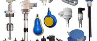
Popular models
The modern market offers many models of alarms . The most popular of them:
- DE-1 (capacitive sensor). Most often, this alarm is used in aggressive environments in the chemical and metallurgical industries. It allows you to control the temperature and level of bulk and liquid substances. Often used in emergency protection installations.
- ESU-1 (electronic level switch). The body of this model is made of high quality steel and fluoroplastic. Most often, ESU-1 is installed in explosive and aggressive environments. The power source is located outside the process environment. The sensor measures the level of oil, alcohol and water. The power supply is made of durable aluminum alloy.
- RU-305 (level relay). This device is designed to monitor the condition of liquid media. Its body is made of special material and can easily withstand temperatures from -50 to +50 degrees Celsius. However, RU-305 must not be used in aggressive chemical environments. Among the disadvantages of this level gauge, consumers note only that it works only in one position, without tilt. Level measurement is carried out by moving a magnet with a float and triggering a reed switch. Measurements have an accuracy of no more than 5 mm.
- SU-100 (level alarm). Sensor for measuring the level of bulk and liquid substances. The SU-100 design contains an electromagnetic relay.
- Rosemount 5600 This radar level sensor allows non-contact measurement of any type of substance. To achieve the most accurate readings, the level gauge must be installed correctly. The device's reading accuracy may be degraded by exposure to electromagnetic radiation. The housing has an explosion-proof design and a display that displays all the necessary information. The Rosemount 5600 can be used to measure tank temperatures. To fully evaluate the capabilities of this equipment, it requires qualified adjustment taking into account the diameter of the pipeline, the length of the level gauge and the distance between the level and the reference point.
It is advisable to purchase complex models only for industrial use. The simplest versions of level meters are suitable for domestic purposes.