A pressure reducing valve is a self-acting valve that is used to reduce excess pressure in a system. Sometimes this valve is also called a pressure reducing valve. The main function of pressure reducing valves is to reduce high pressure to lower pressure. They are widely used in water, steam, oil and gas industries.
A pressure reducing valve can be defined as an automatic control valve with automatic action to reduce increased unregulated inlet pressure to a constant reduced outlet pressure, regardless of changes in inlet water pressure. In this article, we will learn about the functions, types, applications and benefits of pressure reducing valves.
How does a pressure reducing valve work?
Let's try to figure out how pressure reducing valves work.
Let's take a closer look at the design and operation of direct and indirect acting valves.
Direct acting pressure reducing valve
The schematic diagram of a direct acting pressure reducing valve is shown in the figure. Let's consider the main elements and operating principle of the pressure reducing valve.
The liquid pressure at the outlet of the pressure reducing valve in the line diverted from the main one is called reducing pressure.
Spool 1 is located in housing 2, in which spring 3 is also installed; its tension is adjusted by screw 4.
The pressure in the pressure line (Pn) is supplied to the working cavity of the spool without exerting a force on it, since the areas of the spool flanges are equal. The axial forces acting on the spool are the spring force and the force caused by the pressure at the valve outlet (Pred). The position of the spool will be determined by the force of the spring and the reduced pressure Rred. The pressure at the outlet of the pressure reducing valve is adjusted using a screw that tightens the spring.
With an increase in the reduced pressure (Rred), the spool, under the influence of this pressure, will shift (up in the diagram), reducing the flow section area S, increasing the hydraulic resistance. As a result of increased losses, the reduced pressure will decrease to the initial setting value.
When the reduced pressure (Rred) decreases, the spool will move downward under the force of the spring, increasing the flow area. As a result of the reduction in losses, the pressure in the discharge line will reach the setting value.
In a direct-acting pressure reducing valve, a spring acts on the spool on one side, and a reduced pressure on the other. The force of the spring depends on the degree of its compression, that is, on the position of the spool, which, in turn, depends on the flow rate at the valve outlet. In this regard, with an increase in flow through a direct-acting pressure reducing valve, the reduced pressure will decrease.
This feature of the operation of direct-acting valves can have a significant impact on the operation of the valve at high flow rates. Therefore, to operate at high flow rates, indirect-acting pressure reducing valves are used.
Indirect pressure reducing valve
The use of indirectly acting pressure reducing valves reduces the effect of flow on pressure.
The diagram of an indirect-acting pressure reducing valve is shown in the figure.
The liquid is supplied to the valve through hole 9, passing through the gap between the spool 5 and the seat in the body, the liquid enters the outlet line 10. The fluid pressure in the outlet line acts on the lower end of the spool. The liquid from the discharge line, moreover, is supplied through a constant throttle 4 to the upper end of the spool and to ball 1, pressed by spring 2, the prestressing force is adjusted by screw 6. Line 7 is connected to the drain.
The position of spool 5 is determined by the ratio of the pressure forces in the discharge line (reduced) and the pressure in chamber 8.
The amount of pressure in chamber 8 depends on the setting of spring 2, that is, the amount of valve setting pressure can be adjusted with screw 6.
If the pressure in the line diverted from the main setting increases above the pressure, the ball will move away from the seat, allowing part of the liquid to drain. As a result of the appearance of flow through throttle 4, the pressure on the upper end of the spool will decrease (due to losses at the throttle), the spool, under the influence of the reduced pressure, will move upward, reducing the flow area, which will cause a decrease in the reduced pressure to the setting value.
Repair, replacement and adjustment
The performance of the pressure reducing valve can only be determined after its removal and disassembly (in the case of a collapsible design). Oil deposits and dirt on its body are removed with kerosene, gasoline or a special liquid for cleaning carburetors. Particular attention is paid to the spring - it is changed even at the slightest sign of compression, stretching or deformation.
To check the functionality of the valve in a “makeshift” way, just press on the piston or ball. If some effort is required to activate them, the device can be considered serviceable.
The valve is faulty if, during the process of pressing, it jams or does not tighten the hole sufficiently. In the first case, it is pulled out and then thoroughly washed in gasoline. In the second case, it is necessary to select a new spring that ensures tight closure of the hole, and replace the worn-out mechanism with it.
Video: replacing the pressure relief valve
After repairing or replacing the pressure relief valve, it should be reinstalled and adjusted. The adjustment is carried out by a stop screw, the rotation of which compresses or stretches the spring. The pressure value is determined using a liquid pressure gauge.
Note that the valve itself can only be adjusted with the engine not running, and the oil pressure is measured with the engine running.
The oil pump pressure reducing valve is a small but extremely important part of the engine of any car. The performance of the entire power unit depends on its serviceability. Timely diagnosis of valve faults and their immediate elimination will allow you to avoid serious troubles on the road.
Source
How does a pressure relief valve differ from a safety valve?
Reducing and safety valves allow you to regulate the pressure; some models of these devices are produced in bodies of a similar shape; they are adjusted using a screw that regulates the spring preload; their hydraulic circuits consist of similar elements. For these reasons, these valves can be confused. Although there are many more differences between pressure reducing and safety valves, they differ in design, principle of operation and purpose.
Perhaps the main difference is that the safety valve is controlled by the inlet pressure (from line P), and the control valve spool is controlled by the pressure at the valve outlet (from line A). This is reflected in the hydraulic diagram of the valve; the dotted control line on the pressure reducing valve diagram is connected to the output, and on the safety valve diagram - to the input.
Scope of application [ edit | edit code]
These valves are used in hydraulic drives when it is necessary to power several consumers of hydraulic energy (hydraulic motors) operating simultaneously and having different load patterns from one source of hydraulic energy (pump). The need to use a pressure reducing valve is due to the fact that putting one of the hydraulic motors into operation leads (in the absence of this pressure reducing valve) to a change in pressure at the inlet to the remaining hydraulic motors, and consequently to a drop in the forces at the output links of the hydraulic motors. If hydraulic motors are not put into operation simultaneously or have the same load characteristics, then the use of pressure reducing valves, as a rule, is not necessary. For example, a bulldozer blade is usually driven by two hydraulic cylinders. But since both hydraulic cylinders drive the same working body (that is, the blade), their load pattern is the same, and pressure reducing valves, as a rule, are not used in bulldozer hydraulic systems.
In pneumatic drives, the use of pressure reducing valves is mandatory, since, due to the compressibility of air, pneumatic systems are prone to significant pressure fluctuations.
Pressure reducing valve to regulate water pressure
Often the cause of pressure drops is leaking taps and burst pipes. Because of this, a pressure reducing valve in a water supply system is a necessity that is regulated by regulations.
p, blockquote 1,0,0,0,0 —>
The regulator is the most important device; it is used to limit the water pressure in the system. Its use is necessary to avoid emergency situations and to ensure the safety of pipes, taps and other components. Plus, the pressure reducing valve significantly saves water.
p, blockquote 2,0,0,0,0 —>
Pressure reducing valve Danfoss 7bis
Types and designs
According to the operating principles, bypass valves are distinguished with spring and membrane designs. Spring mechanisms prevail in systems where the pipeline cross-section is no more than 200 mm; in other water supply and heating networks, the lever-load principle is used.
Membrane units are increasingly used when working with liquid media that contain solid particles.
Depending on the pipeline environment, bypass devices are intended for:
According to the purpose of the system, they are used for pipelines:
- cold water supply,
- hot water supply,
- heating,
- cooling,
- conditioning.
In heating and water supply systems, bypass valves are distinguished according to their purpose:
- for radiators;
- for boiler and bypass;
- for automatic replenishment;
- for low or high pressures.
This photo shows an overflow valve with a setting scale. Made of bronze and brass, designed for installation in central heating systems.
Along with bypass regulators, the following is installed in the heating design:
- air vent to prevent air locks in pipes;
- three-way valve for mixing or separating hot and cold water flows;
- reverse, preventing backflow in the pipeline.
For industrial and utility networks, designs with a nominal diameter DN of up to 500 mm and a flange connection are used.
In the car there are access devices for:
- turbines;
- fuel supply mechanism;
- engine cooling systems.
The turbine bypass unit discharges the exhaust gases, reducing the pressure force in the manifold. Thus, it protects the engine from overheating.
Purpose
Pressure reducing valves are used for central, autonomous and distribution cold water supply systems. Reducing pressure is necessary, of paramount importance, for the safe use of household and commercial hydraulic equipment.
p, blockquote 3,0,0,0,0 —>
It is clear why a pressure reducing valve is needed, but it is used in:
p, blockquote 4,0,0,0,0 —>
- water supply networks;
- pumping units;
- crop irrigation systems;
- fire extinguishing systems.
Advantages of using a gearbox:
p, blockquote 5,0,0,0,0 —>
- Protective function against various hydraulic shocks and strong pressure drops.
- Reduced water consumption and, as a result, cost savings.
- Significant reduction in noise and vibration levels.
- Stable flow pressure.
A water pressure reducing valve must be installed in the following cases:
p, blockquote 6,0,1,0,0 —>
- At static pressure exceeding 5 bar (1 bar equals 0.1 MPa).
- To prevent pressure drops in the drinking water network of the recommended value.
- If the operating pressure upstream of the safety valve exceeds 80% of its response pressure. For example, if the response pressure of the safety valve is 6 bar, the reducer is installed if the static pressure is above 4.8 bar.
- When high-rise buildings are fed with water from a common pump, and when it is necessary to organize areas with different pressures.
Lubrication system design
The engine lubrication system includes a sump with an oil drain plug, an oil pump with a pressure reducing valve, an oil receiver with a strainer, an oil filter with safety and bypass valves, a system of oil channels in the cylinder block, cylinder head, crankshaft and camshaft, oil pressure sensor with warning lamp and oil filler neck. Some engines have an oil cooler included in the lubrication system.
The oil pan is a reservoir for storing oil. The oil level in the pan is controlled using a dipstick, which has marks for the maximum and minimum possible levels. From the sump, oil flows through an oil receiver with a strainer to the oil pump. The oil receiver can be fixed or floating type. The capacity of the lubrication system of a passenger car, depending on the size and type of engine, can range from 3.5 to 7.5 liters. Moreover, the capacity indicated in the instructions has two meanings - one relates directly to the engine lubrication system, and the second indicates the required amount of oil, taking into account the capacity of the oil filter.
Types of control valves
Spirax Sarco BVR2S Pressure Reducing Valve
Pressure-reducing valves come in two types and differ from each other in their operating principle. They are mainly classified as follows:
p, blockquote 7,0,0,0,0 —>
- Direct acting gearboxes. The operating principle is based on direct contact between the control and measurement components.
- Indirect acting gearboxes. Here the measurement element (for example, a sensor) transmits messages to the controller, which then influences the adjustment element.
The difference between the devices is that if in the first case an additional source of energy from the outside is not required, then in the second case this energy source will always be needed.
p, blockquote 8,0,0,0,0 —>
In addition, based on the scope of use and working environment, a distinction is made between air, gas, oil, steam, water valves, etc. This affects the principle and design features of certain models of control valves. It would be logical to divide safety valves of this type according to the work environment with which it comes into contact - aggressive / non-aggressive.
p, blockquote 9,0,0,0,0 —>
Diaphragm pressure reducer Watts DRV 15 N
Let's say pressure reducing valves for regulating water pressure are divided into piston and membrane. The main difference is that piston valves operate in such a way that pressure differences in the flow at the inlet do not create differences at the outlet. The membranes are opposite, and this can be considered a disadvantage of this type of control valve. Due to their design features, piston valves are more sensitive to contamination, and therefore they need filters, plus timely cleaning.
p, blockquote 10,0,0,0,0 —>
Membrane-type water pressure regulators are more reliable in operation and are not demanding to use; they do not require a significant pressure drop to operate.
p, blockquote 11,0,0,0,0 —>
Spring valves are also used in other systems. Let’s assume that similar safety valves are used to supply the working medium (gas, water, steam or glycol solution).
p, blockquote 12,1,0,0,0 —>
Valtec piston reducing valve
p, blockquote 13,0,0,0,0 —>
Gas reducer with pressure regulator
A reducer is an autonomous device designed to control the pressure of a gas mixture at the outlet of a container or pipeline. The main classification in this case involves the division of control units according to the principle of operation. In particular, there is a distinction between inverse and direct devices. A reverse-acting reducer works to reduce pressure as gas escapes. The design of such devices includes valves, chambers for buffering the mixture, an adjusting screw and fittings. Direct acting means the regulator will work to increase pressure as gas is released.
Reducer models are also distinguished by the type of gas served, the number of reduction stages and place of use. For example, there are gas pressure regulators for cylinders, pipeline networks and ramps (burners). In the case of cylinders, the type of gas will also determine how the device is connected. Almost all models of gearboxes, except acetylene ones, are connected to cylinders using union nuts. Devices working with acetylene are usually fixed to the container with clamps with a stop screw. There are also external differences between the gearboxes - this can be color markings and information about the working mixture.
Recommendations for choosing a pressure reducing valve
Before purchasing a gearbox, you should carefully study all the information about its types, manufacturers, and do not forget about your own requirements and financial capabilities.
p, blockquote 20,0,0,0,0 —>
Don't waste your money, buy a water purification filter. In this way, you will protect the pressure reducing valve from the accumulation of dirt and, accordingly, make its service life longer.
p, blockquote 21,0,0,0,0 —>
Manufacturers
Popular models of pressure reducing valves are Adca, Honeywell, Danfoss model 7bis, Brv2s and SRV 2S Spirax Sarco.
p, blockquote 22,0,0,0,0 —>
The Danish pressure reducing valve 7bis Danfoss with a bronze body has a temperature of the pumped medium from -10 to +80 °C. Working pressure 16 bar. Pressure setting range 1.0-5.5 bar. The factory pressure setting is 3 bar.
p, blockquote 23,0,0,0,0 —>
Danfoss 7bis pressure reducing valve design
Вrv2s and SRV 2S Spirax Sarco - the difference between one and the other is that the Вrv2s pressure reducing valve is made of cast iron with a stainless steel bellows, and the SRV 2S Spirax Sarco is made of stainless steel.
p, blockquote 24,0,0,0,0 —> p, blockquote 25,0,0,0,1 —>
Now you know what a gearbox is and what it is used for. A pressure reducing valve is an indispensable device that is used to limit the water pressure in the system.
Source
Useful tips
Finally, here are some useful tips that may help you avoid problems with the oil pump pressure reducing valve or make it possible to identify its malfunction in time:
- Fill the engine only with high-quality motor oil of the appropriate type and viscosity grade. Lubrication requirements can be found in the vehicle manufacturer's recommendations.
- Never mix different brands of oils, even if they are of the same class.
- Change the oil and oil filter in a timely manner. The regulations for this procedure are also indicated in the car owner's manual.
- Do not allow dirt, moisture, or process fluids to enter the lubrication system.
- Monitor oil pressure. When the corresponding warning light on the device turns on, do not hesitate to go for diagnostics.
- Pay attention to the operating temperature of the engine. Overheating can cause coolant to enter the lubrication system.
- If you decide to replace or adjust the oil pump pressure relief valve without the necessary skills and tools, it is better to use the services of specialists.
To lubricate the camshaft and crankshaft plain bearings, engine oil must be supplied to them under pressure. Otherwise, the service life of these parts will be reduced to several minutes. But excess pressure is also undesirable - it can cause loss of lubricant. In automobile engines, its required value is usually maintained by discharging excess oil from the high-pressure line, which is carried out by the pressure reducing valve of the oil pump.
What is a water pressure reducing valve
First of all, the pressure reducing valve has a couple of other names that more clearly reveal its purpose. A pressure reducing valve is also called a pressure reducer or valve or water pressure regulator. The Latin word reducere actually means “to reduce.”
Using a reducer, you can reduce the water pressure in the pipeline and maintain it at a given value, regardless of the water pressure at the inlet.
Simply put, if the pressure in the water supply system in your home is too high (for example, 6.5 bar), then a water pressure reducing valve can reduce the pressure (for example, to 3 bar). In addition to reducing, the valve will maintain the set pressure (for example, 3 bar), even if the inlet pressure drops (from 6.5 to 5 bar) or rises to 10 bar (without water hammer).
Note: The pressure reducer does not protect against water hammer. Moreover, water hammer can damage the gearbox.
In addition, special reducers can not only reduce, but also maintain the required water pressure in the system if the water intake in the system increases. For example, in the apartment they immediately turned on the water in the shower, in the kitchen and flushed the toilet. I repeat, not all gearboxes have the function of supporting dynamic pressure “after themselves”; I know Valtec and Honeywell.
Possible faults
As mentioned above, the main purpose of the pressure relief valve is to open an additional oil channel, preventing the formation of excess pressure in the lubrication system. But the valve must not only open, but also reliably close this channel - otherwise, at low engine speeds, there is a risk of “oil starvation”. As a rule, this is caused by an insufficiently tight fit of the locking element (ball or cup) to the seat.
The reasons for this may be:
- Loss of spring elasticity.
- Damage to the shape of the valve seat, scratches and chips on adjacent surfaces.
- Foreign objects (wear products of pump gears).
By measuring the pressure in the lubrication system with a pressure gauge, it is almost impossible to detect malfunction of the valve. Its loss can be caused by wear of the pump gears and increased clearances in the camshaft or crankshaft plain bearings.
The most effective way to check the pressure relief valve and the oil pump itself is to test the unit on a special stand.
However, a simple inspection can reveal defects that may adversely affect its operation. These are deep scuffs and scratches on the ball (cup), dirt in the channel. It is also quite possible to assess the condition of the spring. To do this, you will need to measure its length in a free state and when applying a certain force. As a rule, such information is in the car repair manual.
Repair
Restoring the valve's operation comes down to cleaning it and replacing parts.
If the locking element is made in the form of a cup, then special attention should be paid to the condition of the chamfer at its end. Even small scratches on it will cause a loss of pressure.
Sometimes car owners grind the glass to the seat using lapping paste:
The side walls of the cup serve only for precise installation of the working chamfer in the saddle. Therefore, small scratches on them will not affect the performance of the valve. It is enough that the cup moves freely in the channel.
When repairing a valve, you should always remember that its condition does not affect the actual performance of the oil pump. Therefore, troubleshooting and repair of the unit must be carried out comprehensively - starting with assessing the condition of the gears.
How and where to install a water pressure reducing valve
The issue of installing the valve remains debatable, although everything is clear to experts.
Firstly, “how”, unless otherwise stated in the instructions, then a pressure reducing valve can be installed on horizontal, vertical and inclined sections of the water supply system. However, it cannot be placed “upside down”; the direct-acting valve spring cannot work in an inverted state.
Secondly, “where”. I repeat, the task of the water reducer is to reduce the water pressure in the system, and NOT to become a barrier to water hammer. It can reduce water pressure, both for the entire system and for an individual device (for example, a boiler or shower).
An ideal gearbox solves two problems:
- reduce the pressure of the static (closed) system on all valves and mixers in the apartment;
- regulate the pressure at the outlet of the dynamic system when water is consumed.
It is important to note here again that not all gearboxes can simultaneously perform the two listed tasks. Reducers that not only reduce, but also maintain pressure in the system are much more expensive.
Where to place the pressure reducer in the apartment?
So, for the entire apartment, the reducer must be installed immediately after the pair of input shut-off valves with a coarse filter (see diagram).
There is an arrow on the valve body indicating the direction of water movement. This must be taken into account during installation.
Misconceptions [ edit | edit code]
There is a misconception that an internal combustion engine uses a pressure reducing valve, in fact it is a simple safety valve. The fact is that the operating pressure in the pressure reducing valve is taken after it, and in any internal combustion engine the valve is connected to a drain.
Gas or liquid in the main pipeline is often at higher pressure than is necessary for a particular consumer. In order to reduce it to the required value, a pressure reducing valve is used. Such devices are also used to stabilize pressure in hydraulic systems of various drives in transport and in technological installations.
Pressure valve installation
As you can see in the photo of the gearboxes above (with and without a pressure gauge), the devices can be equipped with installation fittings, or they can be sold without them.
The valve fittings play the same role as when installing water meters. They allow you to embed the valve into the system without radically disassembling it. The diameter of the fittings, as well as the diameters of the valve inlet/outlet, is selected according to the diameter of the water pipes. The valve inlet/outlet diameters are indicated on the body.
Please note that the valve inlet and outlet may have different thread types. They can be internal (eg ½F or 3/4F) or external (½M or 3/4M). If you need to make a transition, then you need to use an adapter, for example an adapter (1/2F - 1/2M), in plumbers' slang - a futorka.
conclusions
The fuel system check valve is an important component of this system, the failure of which can cause a lot of problems for the driver. This will be especially painful during movement. Therefore, it is worth using only high-quality fuel, and at the slightest sign of a malfunction, which were listed above, diagnosing the fuel system.
After all, the problem may lie not only in the valve, but also in other small parts. Diagnostics at a service station almost always reveals such faults, so do not forget about timely maintenance of the car, even if everything seems to be in good order.
Tiptronic automatic transmission - what is it and why is it needed?
Battery with AGM technology - what is it and how does it work?
How does the EBD system work in a car?
Setting (adjusting) the pressure valve
The direct-acting valve is adjusted by turning the adjusting screw (or knob) after filling the system with water. By rotating the screw you reduce the system pressure at the valve outlet.
If the valve is equipped with pressure gauges, then we adjust the output pressure using this pressure gauge. If a pressure gauge is not included in the kit, then place a pressure gauge after the valve (at the point where the pulse is taken).
In exclusive installation options, a water pressure reducing valve is installed without a pressure gauge, and pressure gauges are installed before and after the valve. Also in design (before operational) installation options, when there is a lot of space, you can follow the following recommendations (if there is nothing else in the instructions):
- A coarse filter is needed before the valve (it is always installed);
- In systems where it is unacceptable to increase the pressure above the set one (for example, hot water boilers), a safety valve is needed after the valve;
- To service the valve, ball valves must be installed before and after it.
You can see an example of how to install a water pressure reducing valve for horizontal installation with a meter in the figure. Other 7 secure gearbox installation schemes are in the next article.
What are the most common regulator failures?
They can be identified using the following signs:
- the pressure before and after the valve is the same or gradually increases;
- inability to adjust equipment;
- low network capacity – poor water pressure;
- presence of extraneous noise;
- presence of device leakage.
In most cases, the reason lies in a violation of the seal, which can be caused by wear of the o-rings. Limestone scale also prevents the spool from fitting tightly to the body.
Situations in which mechanical destruction of the structure occurs are more rare. These include: a burst spring or its thinning, disconnection of the lower piston from the spool rod or diaphragm rupture.
Reducing valve for water in an apartment: before or after the meter?
You probably noticed that in the pictures and photos used in the article, the gearboxes are located in different places, namely before and after the water flow meter. Let me explain why:
A pressure reducing valve for water in an apartment is usually installed before the meter if you need to regulate the pressure for the entire apartment.
If it is important for you to reduce water pressure for a specific device , for example a hot water boiler or an expensive shower cabin, then the pressure reducer can be placed in front of this device, and not before the meter.
In country houses , especially individual water supply, in order to protect the reducer from water hammer, it is placed after the meter , in front of the check valve, thin filter and inspection ball valve.
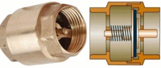
Why do you need a check valve: purpose and device
Float valves for water tanks and containers
Regardless of the design, all the fittings under consideration act automatically, transmitting fluid flow only in the desired direction. They are triggered by the fluid pressure, which must be pre-set. In this case, the fluid path opens, and with a corresponding change in pressure, it closes. The accuracy of regulation is determined by the design of the device.
The devices continue to function even when the movement of the liquid medium in the drive line (for example, a boiler) stops. For example, due to a sudden shutdown of the energy carrier - compressed air or electricity. Check valves operate in a variety of media from liquid to gaseous, including steam or condensate. In sewer systems they work satisfactorily even if the liquid is clogged with fine sand fractions.
Individual injection pumps and pump injectors
The design of fuel systems with pump injectors and individual injection pumps also includes bypass valves. They are installed on the low pressure line. They maintain stable pressure in the low pressure circuit under different engine operating conditions. Pressure adjustment is carried out using a special steel plunger.
The high-pressure circuit also has a bypass valve, which is located directly in the pump-injector housing. This element is involved in the final stage of preliminary injection. By moving the valve, the volume of the high-pressure chamber increases, which makes it possible to close the nozzle needle.
Classification of bypass valves of diesel systems
At the moment, there are several types of bypass valves used in automobile assembly. As was said, they can be used not only in fuel, but also in oil systems. If we are talking specifically about valves for diesel fuel systems, they can be as follows:
- Valves for multi-section pumps;
- Bypass valves of fuel injection pumps of distribution type;
- Throttling valves located at the inlet to the pumping sections of booster pumps (similarly used in injection pumps of distribution types).
There are differences in these valves, and very serious ones. Let's start with valves for multi-section pumps. They are installed on the front walls of the pump housings and are connected to the supply channels, from which the fuel goes to the discharge sections. Such valves can be considered the simplest, because they consist of a body and a spring-loaded locking element (ball or disk). They are, however, divided into subtypes:
- Valve bolt. As you can easily guess from the name, the valve is made in the form of a bolt with a spring-loaded “filling”. As a rule, on the walls of such a bolt there are more than two holes for fuel drainage. The valve itself is screwed into the pump body, and the return line is connected to the nipple;
- Valve-fitting. Like a bolt, it is screwed into the pump body, but the return line is attached to the male thread.
The operating principle of bypass valves for multi-section pumps is quite simple. If the pressure in the fuel supply line is not very high, a disk or ball closes the valve using spring force. In this case, the fuel enters the injection sections. When the pressure in the system increases and conditions are established under which the operation of the injection sections may be difficult, the valve opens - the pressure compresses the spring and excess fuel flows back into the fuel tank through the return line. As soon as the pressure drops below the threshold value, the valve closes again. Let us immediately note that this device is responsible for relieving pressure rather than removing air from the fuel system - this task is performed by the nozzle valve located on the fine filter.
Spare parts for hafei princip
Rear right door molding 1.6 DA4G18
Spare parts for hafei princip
Rear bumper 1.6 DA4G18 Valves that are almost similar to the previous ones can be installed in distribution injection pumps. They are mounted behind the fuel priming pump. Execution options: bolt or fitting. More interesting and somewhat more complex are throttling valves in systems with high-pressure distribution pumps. They combine a jet responsible for draining fuel and a bypass valve. The jet constantly drains fuel into the return line, thereby ensuring its circulation. In some models of throttling valves, the jet is not a remote element, but is built into the device itself. The design is not very complicated - it simply has a small diameter hole that goes into the return line. The main valve opening opens only when the pressure increases strongly. The throttling valve is usually implemented in the form of a bolt, screwed into the injection pump housing and connected to the return line via a nipple.
PRINCIPLE OF OPERATION
The operating principle of this element lies in its design. As previously mentioned, it consists of three working elements and a housing. The elements that can be seen in the figure are:
- Ball.
- Spring.
- Washer.
All parts are secured in a sealed housing. The principle of operation is simple - the ball blocks the path into the system, it is held in place by a spring. But as the amount of liquid increases, the pressure increases. As a result, the load on the spring increases. When a certain load threshold is exceeded, the ball presses the spring, thereby passing liquid through an additional channel. This is how the pressure is released. Subsequently, the working fluid is returned for recycling.
Interesting! Structural elements can be made of various materials. It is important that they do not react with the working fluid.
The puck here is used solely as a support, without playing a special role. The design is very simple and effective, triggering at a certain pressure threshold. Although it may operate with slight variations in frequency, this has virtually no effect on the functionality of the vehicle.
This design is used quite often, used to dump oil or fuel. The design and shape of the valve may be different, but the operating principle is the same.