In order to ensure the correct operation of compressor units used almost everywhere today, a number of additional technical devices are used, one of which is a check valve for the compressor. Such a valve, which is equipped with the vast majority of compressor units today, also protects them from premature failure and ensures smooth starting.
Check valve on compressor
Device Features
Check valves are used in many applications. Such devices most often work in tandem with some kind of tanks or compressors. The main task of a check valve is to prevent loss of pressure built into the system and limit the access of unwanted elements into the system.
In the absence of such a mechanism, the efficiency of the equipment decreases noticeably. For example, compressors are forced to work almost non-stop, which affects not only the operational life of the equipment, but also electricity bills.
Areas of application for check valves:
In addition to maintaining system pressure, check valves prevent liquid media from entering the compressor. With large volumes of distillation, as well as a serious load on the equipment, it is very important to maintain the tightness of the equipment. This point is also critical when working with gaseous compositions, especially hot ones.
In air conditioning and similar equipment, such valves perform two important functions:
Check valves are often used in ventilation technology, both in domestic and industrial areas. Equipment of this type can be seen in apartments - kitchens and bathrooms, in offices, catering establishments, as well as on construction sites and other technical facilities.
The check valve performs the following functions:
In a similar way, check valves are used in plumbing and other systems where it is necessary to shut off unwanted elements.
Types of air valves
All valves can be divided into the following types:
Safety valve: designed for situations where the compressor or pneumatic network exceeds the permissible pressure levels. In this case, it is necessary to quickly relieve excess pressure and protect the system from possible destruction.
Check valve for a compressor: necessary to contain compressed air outside the compressor, preventing it from flowing back into the installation during an emergency or planned shutdown.
An unloading valve , or as it is also called a bypass valve: this is necessary to reduce the load on the electric motor shaft at the moment the entire installation starts.
From the point of view of the properties of the air valve, the quality of operation of the entire compressor station directly depends on:
- tightness of the installed valve, i.e. depending on how tightly it fits
- on how timely the valve closes and opens
- How wear-resistant is the installed valve?
- the degree of its sensitivity to high temperatures and dynamic loads.
You can find out more detailed information on the range of valves for air compressors and their availability in stock by calling us by phone or writing a letter using the feedback form.
Favorable operating conditions for the compressor can be ensured by installing special devices, for example, a check valve. Today it is included in the delivery of most compressors, but from time to time they have to be replaced. Let's take a closer look at the features of the mechanism, as well as its purpose.
Types of equipment
On the market you can find devices of various form factors, as well as purposes. Equipment is usually distinguished by design features, as well as by installation method. The choice of a particular device directly depends on the tasks assigned to it.
Design types of check valves:
The performance of the device is also affected by the material of manufacture. Check valves made of metal alloys are used in industrial structures where heavy loads are expected. Whereas plastic mechanisms can be seen in ordinary kitchens and bathrooms.
Regardless of the design, check valves can be:
The former can often be found in ventilation equipment. Ball valves are used in compressors, and other types are used in gas and plumbing lines. There are also advanced mechanisms with electromagnetic locking.
The cost of the latter, naturally, is noticeably higher. In this case, the blocking occurs not by means of a conventional spring spring, but by means of an electromagnet. But such valves are picky about distillation products and volumes, so manufacturers of industrial equipment most often give preference to more durable and reliable spring analogues.
Check valve on compressor
This part is installed between the piston compressor cylinder and the receiver, and prevents air from returning from the storage tank back to the compression chamber after the unit is stopped.
Important! In addition, the return valve, by holding air in the receiver, allows for a smooth start-up of the equipment. If this part is removed, air will press on the piston and the engine will not be able to crank the crankshaft when starting.
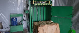
In addition to the reverse, a safety valve must be installed on the compressor. This bypass valve is designed for emergency pressure relief if the pressure switch does not turn off the unit engine. The following photo shows the unloading valve, without which, for safety reasons, the compressor cannot be turned on.
Lada 2101 air suspension "Olive" › Logbook › Air suspension for dummies, part 2 Electrics
Greetings again, gentlemen, today we will continue our story about air suspension for dummies, namely about connecting the electrical part. But first, about some points that I missed in the previous post. No matter how hard I tried, I still missed a point related to the safety of our entire pneumatic system, namely the emergency valve. Emergency valve – valve for releasing excess pressure, i.e. when the pressure in the receiver rises above the permissible value, the valve is activated and bleeds air into the atmosphere, thereby reducing the pressure in the receiver, preventing excess pressure from rupturing the receiver or pneumatic lines.
This can happen due to a breakdown or jamming of the compressor pressure switch, i.e. the compressor will not turn off, but will pump air into the receiver until something cannot stand it, the receiver itself, the air line, the moisture separator or some other component of the system explodes, or the compressor itself simply burns out. Emergency valves can be adjustable - allowing you to adjust the response pressure, and non-adjustable - available with a certain response value. Installed directly into the receiver or from the receiver through a pneumatic line to a more aesthetically suitable location. Adjustment is very simple. Let's say the pressure switch (more on that a little later) is working properly and opens at 10 atm., we tighten the emergency valve adjusting screw and wait until the compressor pumps up the 10 atmospheres we need and turns off, now we slightly unscrew the emergency valve adjusting screw until the moment when it works, i.e. the moment came when the emergency valve itself triggered at 10 atm. and opened to relieve excess pressure. Then we tighten the valve adjusting screw again by one or two turns (depending on the type of emergency valve). The adjustment can be considered complete. We check, turn on the compressor again, and wait until it pumps up 10 atm and turns off, if the emergency valve is completely closed, no air hisses through it, the adjustment was made correctly. If the air still hisses, then press the emergency valve again a turn or two and check again, and so on until the moment when the emergency valve is closed when the pressure switch is triggered. What happens if the emergency valve is not configured correctly? If it is released too much, the compressor will work constantly because will not gain the required pressure into the receiver, and therefore the pressure switch will not work. If it is too tight, the actuation moment can be very high, some components may not withstand such pressure and fail.
A dehumidifier is a device for removing moisture from the air.
I think from the name it is clear what it is needed for. Moisture is separated from the air and accumulates in a special flask, from which it must be drained as it is filled. Moisture is the main enemy of valves and iron receivers, as it causes corrosion. It is mainly installed between the compressor and the receiver, although the most ideal option is to install two moisture separators, between the compressor and the receiver, as well as between the receiver and the valve block. When choosing a moisture separator, be sure to find out in the manual its maximum operating pressure; very often they are simply not designed for the pressure we need, and therefore the pressure causes the flask to accumulate moisture to explode. The next point when choosing is the flask itself; it is better to take a flask with a metal protective flask on top. Photo for example.
And finally, today we’ll talk about electrical connections, how the whole thing is connected and what we need for this. Everyone has their own way of connecting, I’ll tell you how I do it. Let's start with the components. Relay (regular 4-pin automotive relay).
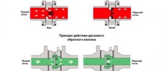
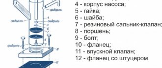
Design and principle of operation
The return design includes the following elements (see figure below):
The return, in addition to the inlet fitting, has a side outlet through which it is connected to the receiver, and 1 thin outlet for connecting a pressure switch.
The check valve works according to the following principle. When the compressor is turned on, air passing through the cylinder suction valve enters the compression chamber, after which it exits through the outlet valve and enters the return inlet fitting (7). When a certain pressure is reached, the valve (6) together with the rubber ring rises and compresses the spring (4). As a result, a passage for air opens. The air moves into the housing cavity (3) and then into the outlet fitting connected to the receiver. After turning off the unit, valve (6), under the influence of a spring and air pressure from the receiver, returns to its place and closes the inlet.
How to make a check valve with your own hands
There are situations when the air compressor return valve has failed, and for some reason it is not possible to buy a new part. In this case, the part can be made by hand.
On the Internet you can find quite complex methods for manufacturing this unit using lathes, milling machines and other equipment. But there is still a way to make a simple homemade valve from improvised materials. A drawing of this unit is shown below.
To make a return you will need a metal pipe or tee, a spring, a coupling, a metal threaded plug and a ball.
The air check valve is manufactured as follows.
After this unit is ready, its inlet pipe is connected to the cylinder of the unit, and the second to the receiver.
Source
Compressor valves - what are they?
An air compressor is a unit whose operating principle is based on compressing and supplying air to pneumatic equipment under the required pressure. Such installations are an indispensable element both in everyday life and in industry, being an autonomously functioning technical unit or being included in more complex electrical appliances (for example, climate control or refrigeration equipment). The schematic diagram of any compressor includes a working chamber and a valve system. And since these devices, like any other mechanisms, can break down, you need to know how they are designed, what types of valves there are, how to choose them correctly or make them yourself. More on all this in the material below.
Adjusting the compressor pressure
As mentioned above, after creating a certain level of air compression in the receiver, the pressure switch turns off the unit’s engine. Conversely, when the pressure drops to the switching limit, the relay starts the engine again.
But often situations that arise force you to change the factory settings of the pressure switch and adjust the pressure in the compressor at your discretion. You can only change the lower switching threshold, since after changing the upper switching threshold upward, the air will be released by the safety valve.
Pressure adjustment in the compressor is carried out as follows.
- Turn on the unit and record the pressure gauge readings at which the engine turns on and off.
- Be sure to disconnect the device from the power supply and remove the cover from the pressure switch.
- After removing the cover, you will see 2 bolts with springs. The large bolt is often designated by the letter “P” with the signs “-” and “+” and is responsible for the upper pressure, upon reaching which the device will be turned off. To increase the level of air compression, turn the regulator towards the “+” sign, and to decrease it, turn towards the “-” sign. First, it is recommended to make half a turn with the screw in the desired direction, then turn on the compressor and check the degree of pressure increase or decrease using a pressure gauge. Record at what indicators of the device the engine will turn off.
- Using a small screw you can adjust the difference between the on and off thresholds. As mentioned above, it is not recommended that this interval exceed 2 bars. The longer the interval, the less often the device’s engine will start. In addition, the pressure drop in the system will be significant. Setting the on-off threshold difference is done in the same way as setting the upper on-off threshold.
In addition, you need to configure the gearbox if it is installed in the system. It is necessary to set the compression level on the gearbox to a level that corresponds to the operating pressure of the pneumatic tool or equipment connected to the system.
Source
Types and principles of operation of valve mechanisms
Currently, the most common types of compressors are screw and piston units. At the same time, screw compressors, for example, those produced by the Belarusian plant REMEZA, are widely used in various industries, and piston compressors are used in everyday life. The latter can be found both in garages of car enthusiasts (compressors such as SO-7B, Forte VFL-50, etc.) and in life support systems for fish in aquariums (Resun compressors, etc.), as well as in household pneumatic tools.
Piston compressors are characterized by a simple design and a relatively small number of parts and components. There are many different designs of such compressor units, equipped with special plate valves that regulate the process of suction and injection of air during operation . Depending on the purpose of compressor units (their performance, power and operating pressure), three types of valve mechanisms can be found:
Inlet and exhaust valves
Inlet and outlet valve assemblies play such a role in the operation of compressor equipment.
Unloader and safety valves
Thus, the compressor pumps air into the receiver cycle by cycle until the specified pressure value is reached. This process is monitored by a special pressure switch (pressostat), which controls the operation of the electric motor by turning it on and off depending on the degree of air compression. As a rule, the pressure switch also includes a starting unloading valve. A pressure switch is connected between the output of the compressor head and the check valve (return valve), which is connected to the receiver and holds the compressed air there.
Important! The safety valve is responsible for relieving air pressure. Its functions include: ensuring a smooth start of the compressor and preventing the return of compressed air to the compression chamber after the engine is turned off.
The necessary pneumatic equipment is connected directly to the receiver, which can be additionally equipped with various devices (separators, filters, pressure equalizers, etc.).
Types of overpressure relief valves
Based on the method of pressing the locking element to the seat, the devices are divided into the following types:
- Spring. The force of elastic deformation of the spring metal keeps the shutter closed. It is selected in such a way that a pressure exceeding a given level pushes the locking element away from the seat. Spring models are available with both constant response pressure and the ability to adjust it. To do this, an adjusting screw is added to the design, which pre-compresses or weakens the spring. During operation, the spring gradually loses its elasticity, and the response value may change.
- Lever cargo. For pressing, the force of gravity is used, acting on a load suspended at the end of the lever. Such a system has wide possibilities for adjusting the response value. To increase it, the load is moved to the end of the lever, to decrease it, closer to the body. In addition to the possibilities for precise adjustment, this design has another advantage: the stability of the release pressure over long periods of time. Lever devices are characterized by large dimensions and weight. They are used as a safety valve for high-capacity compressors installed permanently.
- Electromagnetic. These advanced devices use an electromagnetic solenoid actuator to press the locking element. Such devices operate as an executive element of a centralized automated control system. The pressure sensor can be located next to the valve, or it can be located in a completely different part of the system. Most of them are equipped with an additional working spring. If there is a loss of power or communication with the control system, the relief valve turns into a regular mechanical one.
According to the method of connection, the relief valves are divided into the following types:
- Threaded. The most common type for low pressure relief devices. Easy to install and dismantle even for untrained personnel - a wrench is enough for this. Most often used as an emergency valve for a low-power mobile compressor.
- Flanged. More difficult to install and more expensive, they provide high tightness. used in medium and high pressure systems.
- Welded. Provide maximum tightness and reliability. Difficult to install/dismantle; special equipment and trained personnel are required.
Based on the material from which the device is made, there are:
- Steel. They have high strength and long service life. Withstands great pressure.
- Brass. They are characterized by high corrosion resistance and long service life.
- Plastic. Cheap, but designed for low pressure values.
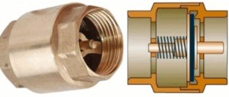
Check valve
A check valve (return valve) is a device that allows compressed air to flow in only one direction . Structurally, it is assembled (see figure) in a metal case (item 3), inside of which the following are located:
On a note! The check valve has a branch for connecting it to the receiver and a small branch for connecting a pressure switch.
Operating principle
The reverse action valve works as follows. Passing through the outlet valve of the piston cylinder, the compressed air enters the return pipe through the inlet fitting (pos. 7). Having reached a certain pressure, the air lifts the internal shutter (pos. 6) and passes through the cavity in the housing (pos. 3) into the storage tank of the receiver. When the compressor is turned off, the spring (item 4) returns the internal shutter to its place, blocking the path of air from the receiver back into the piston cylinder.
Varieties
On the domestic market you can find compressors with returns made of three different materials: aluminum, plastic and brass. At the same time, the aluminum part differs from its analogues in its high reliability and durability. It is built inside the air duct that connects the piston cylinder to the receiver, and is capable of operating under high temperature conditions (up to 200°C). Whereas a plastic return line is installed in budget models operating at a low temperature of the working environment. As for valves made of brass, they are widely used. Such return valves are quite reliable and perfectly maintain their performance characteristics in cases where the air temperature during compression does not exceed 140°C.
Rules for installation and operation of the device
To maximize system protection from overpressure, you must follow the rules for installing and operating the relief valve:
- the connection is made at the outlet pipe of the heating equipment;
- for installation, select the highest possible point of the pipeline;
- the discharge pipe must be connected to a discharge channel connected to the sewerage system;
- the diameter of the valve opening must correspond in area to the internal diameter of the pipe;
- the location of the control device is located in a place accessible for maintenance;
- It is recommended to use quick-release connections;
- if you need to connect pipes after installed valves, then the diameter of the outlet part must be equal to or exceed their cross-sectional area;
- when installing two pressure relief devices, the cross-section of the pipe must exceed the area of the passage openings by a total of 25%;
- It is prohibited to install tie-ins and branches of communications between the boiler and the valve;
- after installation work, you need to make sure that the valve opens at the specified parameters;
- Maintenance should be carried out strictly in accordance with the manufacturer's requirements.
During prolonged use, blockages form on the internal surfaces, which can negatively affect the valve response time.
It is important to use special solutions to clean them. Alcohol or vinegar solutions are suitable for these purposes.
If leaks are noticed on the body, then installing plugs is strictly prohibited, as this can lead to emergency consequences. It is necessary to quickly replace the device by selecting the correct parameters.
To monitor the condition, configure and check the functionality of the valve, you need to use the readings of pressure gauges, temperature sensors and other instruments. This will allow you not to involve specialists, but to solve all the necessary problems yourself.
Safety valve
The relief valve (another name is safety) valve serves for emergency release of pressure and is the final device that protects the pneumatic equipment connected to the compressor from damage.
Attention! It is not recommended to operate the compressor without a safety valve.
Experts also include the following types of relief valve:
Despite minor design differences, their operating principle is identical to a safety valve.
Operating principle of the safety valve
Compressor equipment that is not intended for use in industrial environments is equipped with spring-loaded safety valves. When such a compressor operates in normal mode, it is closed (see diagram). In this case, the air pressure on its plate is balanced by a calibrated spring, which prevents the locking mechanism from opening. If the pressure suddenly increases above the set value, the pressing force of the plate against the nozzle decreases and the valve begins to open. This releases excess air, after which the locking mechanism can return to its place.
Important! If the relief valve does not return to its place for a long time, then the compressor must be turned off and the cause that caused the unauthorized increase in pressure must be eliminated
Bypass valve
The bypass (or overflow) valve maintains the pressure of the working medium at a given level. To do this, through the existing branch there is a constant, and not one-time or periodic, as in a safety valve, removal of an excess amount of the working medium (compressed air, gas, liquid), which ensures pressure stability in the system. Such valves are used, for example, in turbochargers installed on automobile internal combustion engines.
Unloading valve
The unloading valve ensures the release of compressed air remaining in the manifold between the piston block and the return line when the compressor stops. In this case, the pressure at the compressor outlet is reduced to atmospheric pressure. In general, the presence of an unloading valve makes it possible to:
In addition, the unloading valve is used in cases where it is not possible to turn off the mechanical drive of the connected pneumatic equipment . Install it at the compressor outlet in front of the return line.
So, the more productive and powerful the compressor equipment, the more complex the valve system. The simplest check valve for use in a household low-pressure compressor can be made by yourself. But for the installation to work correctly, it is recommended to purchase a factory-made part.
Installation Rules
The overpressure relief valve should be installed as close to the compressor as possible. On low-power mobile units, the installation location is provided by the manufacturer. When installing distributed stationary systems, the distance from the compressor outlet to the valve should not exceed 1.5 meters. It is unacceptable to install an emergency release device after the shut-off valve. If the valve is closed for any reason, the valve will not be able to fulfill its protective function, and the increased pressure can seriously damage the equipment or even cause an accident that threatens the life and health of people working nearby.
Before installing or replacing the valve, it is necessary to completely relieve the pressure in the system and turn off the power to the compressor motor. The threaded connection should be wrapped with FUM tape or plumbing thread. First, the threaded connection is tightened by hand, and only after making sure that the thread goes in smoothly can significant physical effort be applied to tighten it with a wrench.
After installing the valve, you need to test it by increasing the pressure in the system to a threshold value. It should work and reset. If this does not happen, the installation cannot be operated until the cause of the failure is identified and eliminated. If the valve is adjustable, you need to use an adjusting hex key to set its operating reset value, using the pressure gauge built into the compressor control unit.
Safety check valve for a compressor: types, design, DIY production
In order to ensure the correct operation of compressor units used almost everywhere today, a number of additional technical devices are used, one of which is a check valve for the compressor. Such a valve, which is equipped with the vast majority of compressor units today, also protects them from premature failure and ensures smooth starting.
Check valve on compressor
Air conditioning compressor emergency relief valves
— the review must contain the order number; - the order must be paid.
Some manufacturers install emergency valves on compressors of automobile air conditioning systems. If the pressure sensor fails and the pressure rises above a certain threshold, the refrigerant is released through the membrane, which is destroyed. This prevents more serious damage. Once the cause of the emergency has been eliminated, the emergency valve is immediately replaced. Sometimes plugs are installed instead of valves, but it is important to understand that they do not have an emergency release function.
Purpose, design features and scope of application
A check valve installed at the outlet of the compressor head allows compressed air to pass in only one direction - to the receiver or any other reservoir. Thus, this valve prevents the return of compressed air located in the receiver or other elements of the pneumatic system back to the compressor. The greatest risk of compressed air returning from the pneumatic system to the inside of the compressor is during breaks in the operation of the device (if the compressor discharge valves do not fit tightly to the seats), as well as at the time of its startup.
Controls and technical characteristics
The most widely used emergency valves installed on domestic heating and water supply systems have mechanical autonomous control. They operate independently when the maximum pressure is reached and are adjusted manually. Complex production plants and piping systems use safety valves that can be remotely controlled and adjusted. As a rule, when communication with the control center is lost, such a valve turns into a regular mechanical one.
Excess pressure relief valves, based on their purpose, design, and material of manufacture, have different sets of characteristics.
The main ones are:
- Trigger pressure.
- Reset pressure.
- Performance of the working environment reset channel.
- Response speed.
- Time to return to its original state (if the valve does this automatically).
A specific emergency overpressure relief valve is also characterized by the type of design, weight and size parameters, connection dimensions
Main varieties
Check valve systems, depending on their design, can be:
Direct type check valve for high pressure stations
The material of manufacture may also vary, depending on what environments such a device will come into contact with during operation. In particular, it can be either metal alloys of various types or plastic.
Depending on the type of shut-off element used, check valves can be:
The last three types of devices are used for installation in ventilation systems. Among check valves and safety valves installed on compressors, ball-type devices are the most popular, since they are less critical to contaminants present in the working environment.
Check valves with cone (a), flat (b) and spherical (c) shut-off elements
Among the most modern valve systems, it is worth noting electromagnetic type devices, in which the movement of the valve is controlled not by a spring, but by an electromagnet. Meanwhile, due to the rather high cost and not too much reliability, such devices are not very popular, inferior to cheaper and time-tested spring analogues.
Recommendations for selection
When choosing a check valve, you should consider a number of parameters. These include, in particular:
- the intensity of the air flow that will be transported through the system;
- the performance of the air exchange device on which the check valve will be installed;
- the power of the air pumping device, which can be a compressor or fan;
- the degree of contamination of the working environment that will be transported through the elements of the system being created;
- temperature operating conditions.
In addition, it is necessary to take into account the type of medium with which the elements of the valve device will come into contact. This parameter has a direct impact on the choice of valve material, which must have the required durability.