Types and purpose
Tables for drilling machines come in several different types, can be made of different materials and function on different principles. This is a simple fixing device, with the help of which the workpiece is secured in the required position.
With the help of a table, a part is able to change its position and angle during processing; manipulation allows you to perform different types of processing without removing or moving the part. The methods for fixing equipment are as follows:
- using vacuum and differential pressure;
- mechanical devices;
- the part is held on the table independently due to its heavy weight.
For amateurs who are planning to make a table for a drilling machine with their own hands, the second fixation option is most suitable.
The workpiece being fixed in different installations has a different number of degrees of freedom - two or three. In the first case, she is able to move only along the X and Y coordinates; in the second, the ability to move up, down or along the Z coordinate is added. For home use, two degrees of freedom is quite enough.
This is interesting: Do-it-yourself lathe from a drill - instructions with drawings, photos and videos
Coordinate tables
| PSP-420 | Table size 420x204 mm | Longitudinal movement of the work table 195 mm | To order | 63 648 q 1,781 BYN 304,104 KZT 56,361 KGS 351,784 AMD $724,613 € |
| KRS-475 | Table size 475x155 mm | Longitudinal movement of the work table 330 mm | To order | 14,688 q 411 BYN 70,177 KZT 13,006 KGS 81,181 AMD $167,141 € |
| KRS-425R | Table size 425×240 mm | Longitudinal movement of the work table 225 mm | To order | 46 008 q 1,287 BYN 219,821 KZT 40,740 KGS 254,287 AMD $523,443 € |
| BF-16 | Table size 400x120 mm | Longitudinal movement of the work table 220 mm | To order | 28 224 q 789 BYN 134,851 KZT 24,992 KGS 155,995 AMD $321,272 € |
| BF-20 | Table size 500x180 mm | Longitudinal movement of the work table 280 mm | To order | Price on request |
| BF-30 | Table size 700x180 mm | Longitudinal movement of the work table 280 mm | To order | 54 881 q 1,535 BYN 262,216 KZT 48,597 KGS 303,329 AMD $624,529 € |
| AKP-2 (204) | Table size 425x240 mm | Longitudinal movement of the work table 225 mm | To order | 52,999 q 1,483 BYN 253,224 KZT 46,931 KGS 292,927 AMD $603,511 € |
| AKP-2 (205) | Table size 600x240 mm | Longitudinal movement of the work table 400 mm | To order | Price on request |
| AKP-2 (206) | Table size 730x210 mm | Longitudinal movement of the work table 500 mm | To order | Price on request |
| KT120 | Table size 400x120 mm | Longitudinal movement of the work table 220 mm | To order | 45 430 q 1,271 BYN 217,060 KZT 40,228 KGS 251,093 AMD $517,438 € |
| KT179 | Table size 500x180 mm | Longitudinal movement of the work table 287 mm | To order | 64 080 q 1,793 BYN 306,168 KZT 56,743 KGS 354,172 AMD $729,617 € |
| KT180 | Table size 700x180 mm | Longitudinal movement of the work table 480 mm | To order | 74 635 q 2,088 BYN 356,598 KZT 66,090 KGS 412,510 AMD $849,719 € |
| KT210 | Table size 730x210 mm | Longitudinal movement of the work table 480 mm | To order | 78 942 q 2,209 BYN 377,177 KZT 69,904 KGS 436,315 AMD $898,761 € |
| WT-7 | Table size 180x130 mm | Longitudinal movement of the work table | To order | 18,060 q 505 BYN 86,288 KZT 15,992 KGS 99,818 AMD $205,174 € |
| WT-10 | Table size 225x180 mm | Longitudinal movement of the work table | To order | 35 194 q 984 BYN 168,153 KZT 31,164 KGS 194,518 AMD $400,339 € |
| WT-12 | Table size 302x241 mm | Longitudinal movement of the work table | To order | 64,786q 1,813 BYN 309,541 KZT 57,368 KGS 358,074 AMD $737,624 € |
| WT-15 | Table size 381x255 mm | Longitudinal movement of the work table | To order | 71 265 q 1,994 BYN 340,497 KZT 63,105 KGS 393,884 AMD $811,687 € |
| WTS-7 | Table size 180x130 mm | Longitudinal movement of the work table | To order | 26 161 q 732 BYN 124,994 KZT 23,165 KGS 144,592 AMD $297,252 € |
| WTS-10 | Table size 255x180 mm | Longitudinal movement of the work table | To order | 48,719 q 1,363 BYN 232,774 KZT 43,141 KGS 269,271 AMD $554,469 € |
| WTS-12 | Table size 302x241 mm | Longitudinal movement of the work table | To order | 70 376 q 1,969 BYN 336,249 KZT 62,318 KGS 388,970 AMD $801,678 € |
Purpose and types
In essence, a coordinate table is a movable metal platform on the surface of which a workpiece processed on a machine is mounted. Various methods of such fixation are possible:
- using mechanical devices;
- by means of vacuum;
- due to the own weight of massive parts.
Mechanical two-axis table fixed in standard grooves of the working surface of a drilling machine
Depending on their functionality, coordinate tables for drilling machines can have two or three degrees of freedom. Thus, some models can only move in the horizontal plane (X and Y axes), while more technologically advanced ones can also make vertical movements (Z axis). Tables of the first type are used when processing flat parts, and devices with the ability to move vertically are equipped with drilling machines that process parts with complex configurations.
At large industrial enterprises where large-sized parts are processed, long coordinate platforms are often used, on which, thanks to the presence of a special mounting frame in their design, both the workpiece and drilling equipment can be installed. Most of the models are mounted on the machine itself or on the surface of a workbench.
Various types of drives can be responsible for moving the coordinate table:
- mechanical;
- electric;
- equipped with a CNC system.
Coordinate table with electric drives
Drive types
When creating a small machine, a coordinate table with mechanical feed is often installed. However, there are quite a few types of drives, the selection of which is based on the following criteria:
- processing speed;
- positioning accuracy;
- equipment performance.
In most cases, an electric drive is chosen, during the creation of which a motor is installed.
The essence of this mechanism is to convert rotation into reciprocating motion. The following types of gears are distinguished for the design in question:
When creating a drive, a belt drive is often chosen. A homemade belt-type mechanism is cheaper than others, but the belt quickly wears out and stretches. Also, belt slippage determines the low accuracy of the moving element. All elements of the coordinate steel are connected to each other by welding. In this case, the threaded method of connecting certain parts is also used.
In conclusion, it should be noted that a home-made design is suitable exclusively for equipment for domestic use, since it is practically impossible to achieve the accuracy that industrial models have.
Materials and tools used
To work you will need a welding machine, a drilling machine, an angle grinder with discs, a hammer, brushes, and a corner. At the preparatory stage, it is necessary to select the material for the base of the device, the control mechanism and guides. The accuracy of the future operation of the device, service life, reliability of the device, and financial costs of manufacturing depend on the correct choice of these components. To create a base, one of three metals is suitable:
- cast iron;
- steel;
- aluminum.
The first material is rarely used in work. The reason lies in its fragility, heavy weight, and fragility. Steel wins by these criteria, which is why it is often used in production. Its only drawback is its high cost. Aluminum is much more affordable. Its advantages are lightness and softness. But it is only suitable for small-sized tables, since the malleable metal cannot withstand large heavy parts.
Making your own changing table and mattress for it
When making a coordinate table with your own hands, you need to think about what type of drive the device will have. According to the control method, manipulators are divided into three types: mechanical, electrical, and program control. The latter drive is not used in self-production. The electrical analogue gives a small error, but in private conditions it is problematic to use. For personal home appliances, a more suitable type of control is mechanical. However, it has a drawback - the lack of perfect accuracy.
For manual production, rail or cylindrical guides are suitable.
Cast iron
Steel
Aluminum
Mechanical drive
Electric
Software controlled
Product Description
An inversion table is used to treat a wide variety of spinal disorders. Moreover, with its help you can also strengthen the muscular corset and ligaments of the back.
An inversion table is a simulator that you can use independently and at home. Simply put, if you know the safety precautions and rules for performing exercises on it, you can use it without a trainer or supervision from doctors.
Inversion table DFC XJ
Despite the undoubted therapeutic effect provided by this simulator, it is not a panacea and in most cases is used only as an additional method of treatment to the main therapy. The reason is that it only improves the body’s compensatory functions and reduces the symptoms of diseases.
In addition, even in cases where the simulator is indicated for treatment (for example, with muscle tension or osteochondrosis), its use may be contraindicated in individual cases. Simply put, you should not use an inversion table without first consulting a doctor.
Purpose: what and where is it used?
An inversion table is used as an auxiliary treatment method for a relatively large number of diseases of the musculoskeletal system. In addition, its use is justified not only for the treatment of such diseases, but also for their prevention.
So the inversion table is used for:
treatment of degenerative diseases of the spine (for example, osteochondrosis); relieving excess tension in the muscles (here the device acts as a muscle relaxant); prevention of varicose veins, scoliosis, osteochondrosis; strengthening the muscle corset and ligamentous apparatus; increasing flexibility and, accordingly, range of motion; general relaxation and stress relief; stimulating microcirculation of blood in the back and the flow of lymphatic fluid.
Performing an exercise on an inversion table
Despite the possibility of preventing scoliosis with the help of an inversion table, using it if you already have scoliosis is not only pointless, but also dangerous. The fact is that those therapeutic exercises that are performed on such simulators are usually contraindicated for scoliotic disease.
The essence and advantages of application
The undoubted advantage of the inversion table is its autonomy. Simply put, the patient can perform various necessary exercises himself, without supervision from a doctor and at home.
In addition, a huge advantage of this simulator is that it can be made independently, and the process of manufacturing parts and subsequent assembly can be done even by a person inexperienced in such things.
All the necessary drawings and even video instructions for making an inversion table with your own hands can be easily found on the Internet.
If we talk about the therapeutic effect that an inversion table has, there is also a noticeable advantage of the device. The fact is that in case of inflammatory and dystrophic pathologies of the back, which are accompanied by pain, the exercise machine has a noticeable effect within 15 minutes of use.
Another advantage is that you can use an inversion table every day throughout your life, thereby reducing the risk of developing back diseases and eliminating symptoms (primarily pain) of existing diseases.
Equipment use
Before starting to operate the coordinate base, the master must study the safety rules, equipment features, as well as the lighting requirements in the room where the work is taking place.
The table is activated in the following ways:
- mechanical movement;
- use of electric drive;
- installation of CNC equipment.
The first or second option, if you implement it yourself, will be the most suitable.
Separately, it is worth mentioning such design options as a rotary table and a cross.
The first one is capable of rotating around its own axis and is the most convenient option if you need to process parts with axial symmetry, round and disc-shaped workpieces.
The cross drill table is more common in everyday use and provides the ability to move the workpiece in two directions: X and Y.
Add an adjustable end stop
1. To make the body of the stop stop J , cut two 51x73mm pieces from a 19mm thick board and glue them together face to face, aligning the ends and edges. When the glue is completely dry, cut a 6x5 mm groove in the middle of the back of the case (Fig. 5).
K to the specified dimensions and glue it using double-sided tape to the right side of the housing J (Fig. 5). Install a Forstner drill with a diameter of 13 mm into the chuck of the drilling machine and drill a 10 mm deep recess in the left side of the body, as shown in the figures and photo C. Then, without moving the parts, install a drill with a diameter of 6 mm and drill a through hole in the center of the recess through both parts.
3. Separate stopper K from body J. Using a Forstner drill with a diameter of 19 mm, drill 10 mm deep recesses in the stopper and body exactly above the 6 mm holes (Fig. 5). To align the centers before drilling, insert dowels with a diameter of 6 mm into the holes. Then, with a 7mm drill bit aligned in the middle of the 6mm slot on the back of the case, drill a through hole as shown in the picture.
(Photo C) - Secure the parts by placing the stopper K at the bottom and pressing the edge of the body J with the groove against the stop of the drill table. Drill a 13x10 mm countersink in the side face of the housing. (Photo D) - Secure the movable stopper K to the screw using washers and a nut, insert the screw into the housing hole J and screw it into the nut that is epoxy glued into the counterbore.
, secure the nut into the 13mm recess of the body J. Then cut out the slider L of the specified dimensions and glue it into the groove on the back side of the body, flush with its right edge (Fig. 5).
5. Apply a clear finish coat to all flying parts. After drying, place a wide 6mm washer on the button head screw and insert it into the hole in the stopper K. Place the second washer on the screw and then screw on the nut. Tighten the nut so that the stopper does not wobble, but the screw can rotate. Now connect the stopper to the body J (photo D ), turning the screw until both parts touch.
6. Using epoxy glue, secure the plastic knob nut to the end of the button head screw. Insert a hex head screw into the housing hole J at the back and add a washer and handwheel nut at the front (Figure 5). To use an adjustable end stop, first set the distance between the body and the stop to approximately 12 mm. Moving the slider with a hexagonal screw head in the guide aluminum profile, using a tape measure or measuring ruler, set the stopper at the required distance from the drill. Secure it by tightening the front handwheel nut. Now finely adjust the distance to the drill by rotating the side handwheel nut. The handwheel lock nut and L are located exactly in the center of the body, so you can use the adjustable stop to the right and left of the drill simply by flipping it over.
7. Assemble the clamps (Fig. 2). Insert the hex heads of their screws into the grooves of the aluminum profile guides. Now the drilling machine is ready for real work and can rightfully be called a carpentry machine.
Useful tips
The instructions, which describe how to make a coordinate table with your own hands, explain the process step by step. However, minor problems may arise during operation. To avoid them, it is recommended to adhere to safety precautions and take into account the advice of experts. The most important of them:
- if you plan to process plastic or wood, then the base of the manipulator can be made of aluminum;
- with device dimensions of 35 x 35 cm, it is advisable to adjust the total length of the guides to 30 cm;
- to protect the device from chips before installation, it is recommended to place a piece of plywood under it;
- when using cylindrical guides, there is no possibility of connecting a lubrication supply system, so all parts must be lubricated manually;
- When assembling, it should be taken into account that the plain bearing provides better machining accuracy, while its counterpart (friction bearing) leads to some play.
Making a table for a laptop with a cooling system with your own hands
To carry out welding work, safety precautions must be observed. It involves the use of special clothing, a protective mask (shield), suede or tarpaulin gloves. The room in which the assembly is carried out must be ventilated or have a high-quality exhaust hood. When working outdoors, a canopy is required. Near the workplace, means and materials must be prepared to extinguish a possible fire.
The manufacture of a simple type coordinate manipulator can be mastered by a master with welding skills . It is not difficult to obtain a reliable and convenient product if you strictly follow the conditions of the drawing and the assembly algorithm. The home device allows you to engage in small-scale production of metal, wood, and plastic parts. The service life of such a device depends entirely on the quality of installation and the volume of drilling and milling work performed.
This is interesting: Design features of argon arc welding machines
Small milling table (drawings, components)
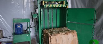
Quite often, a small-sized base is installed on a support, in which a manual router is placed. If necessary, it can be removed and put aside, freeing up space inside the workshop.
Small table for hand router
Such a device is made from solid hardwood (maple) and birch plywood. Drawings of assemblies and individual parts are shown below.
| The sidewalls will be installed according to the attached diagram. This is what the table looks like in cross section. |
| Top view of the table. The main dimensions are shown here. The table cover is made of two layers. |
| Manufacturing sequence. Carrying out markings before starting to cut out the window. Work is carried out in the lower layer. |
| Sequence of making the top layer. |
| Both layers are glued together. Installation of guide strips. They are needed to cut out the window using a router. |
| Milling relative to guide bars. |
| Design of a rip fence placed on a table. |
| End scarf. They are installed at the ends of the stop. |
| In the middle part, two additional gussets are installed for additional reinforcement. A hood for dust extraction is installed. The hose from the vacuum cleaner will be connected to it. |
| Shield holder. The shield itself is made of plexiglass. |
| During the milling process, you need to firmly press the parts against the table and stop. Combs are used for this purpose. At the same time, the device of the locking block is shown. |
To make such a device, parts are needed. Their sizes, quantities and materials are shown in Table 1.
Table 1: Accessories for making a table for a manual router
| the name of detail | Designations on the drawings | Finished dimensions, final | Characteristics of semi-finished products | |||
| Thickness, mm | Width, mm | Length, mm | Type of material for manufacturing | Number of details | ||
| Table details | ||||||
| Panel A | A | 19 | 522 | 622 | Birch plywood | 1 |
| Panel B (cladding) | B | 3 | 522 | 622 | Solid fiberboard | 1 |
| Longitudinal edge overlays | C | 19 | 40 | 660 | Solid maple | 2 |
| Side edge trims | D | 19 | 40 | 560 | Solid maple | 2 |
| Legs | E | 19 | 292 | 521 | Birch plywood | 2 |
| Ties | F | 19 | 76 | 521 | Solid maple | 4 |
| Power cord strip | G | 19 | 51 | 420 | Solid maple | 1 |
| Table support | ||||||
| Vertical support wall | H | 19 | 152 | 661 | Solid maple | 1 |
| Horizontal base | I | 19 | 76 | 661 | Solid maple | 1 |
| Gussets for the dust extractor pipe | J | 19 | 64 | 79 | Solid maple | 2 |
| End plates | K | 19 | 121 | 191 | Solid maple | 2 |
| Additional accessories | ||||||
| Holder | L | 19 | 127 | 127 | Solid maple | 1 |
| Shield | M | 6 | 70 | 127 | Plexiglas | 1 |
| Comb clamp | N | 19 | 45 | 203 | Solid maple | 2 |
| Stop block | O | 19 | 45 | 76 | Solid maple | 2 |
Manufacturing instructions
Once the type of material and type of construction have been selected, they proceed directly to work. At the first stage, it is necessary to draw up an accurate drawing indicating the dimensions of all parts. If there is no ready-made scheme, you should develop it yourself. The final result is largely determined by the accuracy of the location of the parts relative to each other. The process of assembling a coordinate table with a mechanical drive consists of the following steps:
- the main assembly is welded from a metal profile 2 mm thick;
- check the geometry of the cross and clean the seams with a grinder;
- a block of guides is assembled on the welded central unit (travel is 94 mm);
- nuts of size M10 are installed inside the profile;
- a handle with a bearing is assembled on a threaded rod (M10);
- weld the base from a corner having a U-shaped configuration;
- screw all parts onto the built-in nuts;
- lubricate moving elements with technical oil;
- install the device on the bed of the milling machine.
The manipulator structure should be assembled on an absolutely flat surface.
Review and comparison of factory models
| Model | KT70 | KT150 | G-5757 | KRS-475 |
| Table dimensions, mm | 200*70 | 200*200 | 312*140 | 475*155 |
| Longitudinal movement, mm | 134 | 150 | 203 | 330 |
| Transverse movement, mm | 46 | 150 | 125 | 150 |
| Vernier division, mm | 0,05 | 0,05 | 0,02 | 0,02 |
| Weight, kg | 1,14 | 4,9 | 17 | 23,5 |
| Price, rub | 8046 | 16510 | 11900 | 14000 |
- Types and varieties of metal cutters for the machine
- Classification of turning cutters for metal: carbide, with replaceable inserts, alloyed
- Technology for sharpening drills of various types
- Metal machines
- Woodworking machines
- Universal machines
- Special machines
- Machine equipment
- Machine Reviews
- Contacts and advertising
Machine Reviews
- Review of the FSSH-1A milling machine: design and technical parameters
View all test reviews
- Milling machine knowledge test
- Lathe knowledge test
- Test for knowledge of industrial machines and accessories for them
Machine passports
Production of homemade versions
When manufacturing, you should initially select the material of manufacture:
- Cast iron is an expensive, heavy, brittle material. It is quite rarely used in the production of a drilling machine.
- Steel is a strong, hard, durable metal, which also has a fairly high cost. Steel can be called the most attractive material.
- Aluminum is a light, fusible, but expensive and soft material. It is quite easy to use in the manufacture of any machine parts. As a rule, mini equipment is created using this alloy.
The above materials are selected for a full or mini machine.
Base material
Before you start creating a device, you need to think about what materials and spare parts to use. Preliminary preparation is necessary so that they can give the future creation the following characteristics:
- Normal working weight so that one person can work with such a table without noticeable difficulty.
- Simplicity and versatility of installation. A good product must be suitable for different types of drilling equipment.
- Maximum cost savings on manufacturing. If development turns out to be too expensive, wouldn’t it be easier to buy a ready-made item?
Most often, these requirements are met by the following common and economical options:
- steel;
- metal;
- cast iron;
- aluminum;
- duralumin.
If the table is needed mainly for drilling soft materials (wood, plastic), then aluminum will be the best option. It is extremely light and has sufficient strength.
If you have to work with metals, drill serious parts to a relatively large depth, then you will need something more durable - steel, cast iron, iron. These are heavy materials, but the loads they can withstand are impressive.
Easy to make additive
Discussion
- Can drills be replaced with edge routers? There will be revolutions like an additive machine +/-. The machine turned out to be interesting, well done!
- The device is very good, but I wanted to ask: are the drills clamped normally from the additive, since they have a beveled edge?
- Yes they clamp normally. The beveled part needs to get between the clamping jaws of the drill chuck. There are three legs in the chuck and the beveled part of the drill base must be placed between two adjacent legs. And in the same way, I take a couple of filler drills with me for installation and clamp them into a screwdriver if I need to move the fasteners on site.
- There is a drawing, but it is not detailed. There the emphasis was more on the amount of material and the approximate appearance. And there is no assembly drawing with markings of mounting holes, etc. This was done on the fly.
Advantages and disadvantages of self-production
A coordinate table is an additional structure to a milling, drilling metal or woodworking machine. Thanks to it, you can increase equipment productivity by reducing the labor intensity of the parts processing process. The workpiece is simply fixed on the working surface and can move smoothly along a given path.
Homemade coordinate tables have the following advantages:
- small dimensions;
- simple design form;
- controlled mechanically;
- used in handicraft production.
Their main advantage is saving money. Making such a design from scratch will cost much less than buying a factory-made manipulator. Of course, there are a number of difficulties when making it yourself. A suitable drawing is needed, according to which the required trajectory of the workpiece will be set. If there is no someone else’s experience, then you will have to create it yourself, but any error when drawing the diagram will make itself felt during work. In addition, a homemade table is only suitable for small-scale production, since the simplest homemade mechanisms wear out much faster than factory ones.
For mass production of parts and their processing, only a factory model of a coordinate table is suitable.
Simple design form
Small dimensions
Mechanical control
Saving money
Homemade coordinate table, perhaps? — Homemade machines
Absolutely right, transverse and small longitudinal from a lathe, cast iron bed from a Komunaras drill with a screw feed, the working field turned out to be 300x300, mainly for processing small steel parts and is being invented, now everything is still in the process of experimentation and debugging, but there is positive experience with steel, It seems to cope with cutters up to 6 mm normally, but with a larger diameter problems begin (all mainly from using a 1200 W impact drill as a head), you need to come up with a tough, powerful head, when installing an angle grinder instead of a drill, you get a small grinder
Here’s a photo I took (though the quality is not very good) while working with steel, one has an x35 plate on it, the second photo shows the actual part for working with which the device was intended to work with (in the photo, one part is before processing, the second one, clamped in the chock, has already been passed through three times)
Modified on January 25, 2014 by BM_906
Guides
The guides along which the coordinate table moves are an important element of its design, since not only the smooth movement of the part, but also the accuracy of its processing depends on their quality and design features. Both in serial models and in homemade coordinate tables, the guides can be of rail or cylindrical type.
Smooth and accurate movement along the guides is ensured by the built-in carriage and bearing units. In cases where increased movement accuracy is required from the coordinate table, sliding bearings are used in its guides, since rolling bearings create significant play in the supports, although they reduce the friction force more effectively.
Bearing unit design
Guides for coordinate tables, depending on the type of carriage, are:
- equipped with an enlarged flange used to attach the structure to the bottom of the table;
- wafer-type, which are fastened in the usual way.
Dovetail guide
Start from the table
1. For base A , cut two pieces of 12x368x750 mm plywood (we took birch plywood, as it is smoother and has practically no defects. You can also use MDF). Glue both pieces together and secure them with clamps, aligning the edges (Fig. 1).
2. From hard hardboard 6 mm thick, cut out the upper side B , front C and rear D linings according to the dimensions specified in the “List of Materials”. Mark a cutout with a radius of 10 mm on the leading edge of part D (Fig. 1). Cut out a cutout and sand its edges (the cutout will help you easily remove the insert plate E ). Now apply glue to the back of the hardboard overlays and glue them to the plywood base board (photo A).
After applying glue to the underside of parts B, C and D, place them on the plywood base plate A. To prevent movement, attach the parts to each other and to the base with masking tape. Then compress the adhesive using 19mm thick spacers and 40x80mm clamping bars.
3. Mark a cutout with a radius of 83 mm on the rear edge of the table (Fig. 1), cut it out with a band saw or jigsaw and sand it smooth.
4. To determine the position of the central cutout measuring 89x89 mm in the base plate of the table, insert a drill with a diameter of 3 mm into the drill chuck, align the cast iron table of the machine with it and fix it. Place the cover table on top and align it so that the drill is aimed at the middle of the opening for the liner E formed by parts B, C and D. If the cast iron table protrudes beyond the front edge of the table top, slide the table forward, aligning both edges. Secure the position of the overhead table with clamps. Now drill a through hole with a diameter of 3 mm in the plywood base plate of table A. Remove the table and turn it over. Mark the 89x89mm cutout, centering it around the 3mm hole. Then drill 10mm diameter holes in the corners and use a jigsaw to cut out the cutout. Now cut out the insert plate E to the specified dimensions.
5. If the metal table of your machine has through grooves, cut a groove on the underside of the overhead table for inserting an aluminum guide profile (Fig. 1). If there are no through grooves in the metal table of the machine, drill two mounting holes with a diameter of 6 mm. Place them approximately halfway between the center and the rear edge of the table and as far apart as possible. Then re-attach the top of the table and mark the position of the holes on its underside. Cut a groove for the aluminum profile that goes through these holes.
Design selection
When choosing a design, you need to decide on its dimensions. If equipment that processes a part will be installed on a coordinate table, then its dimensions must be taken into account. If it is needed to fix the workpiece, it is mounted on the frame of the drilling equipment, and its width and length will be about 35 x 35 cm.
Tables are also distinguished by the type of fastening:
- When making a coordinate table with your own hands, the structure is equipped with a mechanical fastener. This is the simplest solution in terms of implementation, but it has a number of disadvantages. For example, it often leads to processing errors, and there is a risk of deformation of the product surface.
- Vacuum fastening is considered the best option. With its help, precise positioning of the workpiece on a horizontal plane is ensured. When an air stream is supplied into the gap between the tabletop and the workpiece, the pressure in this area changes. Thanks to this, it is possible to perform processing more efficiently (without mechanical damage to the product).
- Workpiece weight clamping is suitable when using a drill press to machine heavy parts. Due to its mass, the base product remains in the same place even with strong impact.
The functionality of the table depends on the number of degrees of freedom:
- If there is only one, then the workpiece can only be moved in one direction (this is a good option for processing flat products).
- If there are two degrees, it becomes possible to move the workpiece along X and Y coordinates.
- If there are three of them, then the part can move up, down and along the Z coordinate.
If the table is made for home production and processing of parts, then using two degrees of freedom is more than enough.
When making a coordinate table with your own hands, it is important to decide for what purpose it will be used. The parameters of the manipulator are selected in accordance with the dimensions, weight and shape of future workpieces. To work with various parts from metal and wood, a complex multifunctional mechanism is made. Usually, home craftsmen have enough capabilities of a small-sized table with mechanical fasteners and two degrees of freedom.
Mechanical
Vacuum
Fastening under the weight of the workpiece
Manufacturing of load-bearing elements
The materials for making the table frame are:
- cast iron;
- metal;
- aluminum.
The latter material is used for circuits with light loads and low torque forces. This option is acceptable when drilling wood or plastic.
Drawn aluminum frame profile, mounted on threaded connections. This creates a solid foundation. Advantages of the material:
- low weight;
- accessibility;
- ease of installation.
Many companies produce ready-made kits for assembling tables with your own hands.
Drilling machine with cross table
Cast base structures are often cast iron. Their weight is significant, but the forces they can withstand are quite high. Such tables are used for large production volumes. Installation is carried out on the foundation, permanently.
A welded frame is the best option for both production facilities and home use. The main thing is to reduce the welding stresses of the metal by releasing it when welding with your own hands. Otherwise, when the engine picks up speed, cracks may appear in the frame.
For drilling machines, two table technological schemes are used:
- cross;
- portal
Drilling machine with gantry table
The first is used for bulk workpieces. It makes it possible to carry out other manipulations on the fixed workpiece. With this arrangement, access to the part is provided from three sides.
The portal pattern is used when drilling flat products. It is easier to manufacture and has increased processing accuracy.
Materials and mechanisms of structural elements
The durability of the structure and cost depend on the material of the product. You should immediately decide what type of table it will be - steel, aluminum or cast iron. The second important step is to decide on the control mechanism. You should also decide whether the drive should be mechanical or electric. The third step is to select guides. This will affect the processing accuracy of the workpieces.
Base
The following materials are used for the base:
- Cast iron. Expensive, heavy material turns out to be very fragile in operation, so it is used extremely rarely in the production of a drilling machine.
- Steel. The material is the most highly durable and durable. Its main drawback is the cost. Not every master will be able to purchase it.
- Aluminum. Light and soft material is easier to work with. It is not as expensive as steel. But it is not suitable for making a large-sized table, since it will not withstand the heavy weight of large workpieces. This is an ideal option for creating mini-equipment.
If the master processes metal workpieces, then it is better to make the table from steel or cast iron. True, you should immediately evaluate your costs: perhaps purchasing a ready-made manipulator will cost less than expensive hardware. An aluminum tabletop is suitable for working with wood or plastic.
Cast iron
Steel
Aluminum
Drive unit
The drive is a control mechanism with which the coordinate table will change its position. It happens:
- Mechanical. The easiest way is to make it yourself. It allows you to significantly reduce the cost of the table. The basis is a conventional screw or belt drive - this is enough to set up small-scale production. Mechanics are not capable of providing 100% accuracy, and this is its clear drawback.
- Electric. It guarantees zero error when performing work operations, but it is very difficult to do it yourself. Often found in factory models of tables. If there is no own power source near the workplace, this option will not work.
Models with CNC (computer numerical control) should be included in a separate category of coordinate tables. This is high-tech equipment that is used by large enterprises for production in huge volumes. Their main advantages: good performance, as well as complete or partial automation of the process. Disadvantages: high cost, such a drive is not suitable for some parts.
Mechanical
Electric
CNC
Guides
The accuracy of the workpiece processing depends on these elements, so they need to be selected correctly. Among those that you can do with your own hands, the following are distinguished:
- Rail. Rectangular guides are considered structurally more advanced. When using them, lower friction losses are observed and serious errors are avoided. It is possible to connect a lubricant supply system.
- Cylindrical. The use of rounded guides is fraught with high heating due to friction. They are suitable for machines of the so-called small category, but you will have to lubricate all the mechanisms manually.
The guides are made with a carriage and bearing units. The use of plain bearings will ensure high precision machining of the part. The use of a rolling shaft support will reduce friction and extend the service life of the manipulator.
The rolling bearing can cause noticeable play, which reduces the accuracy of the workpiece.
The carriage is a block of guides (mechanism assembly) that moves directly along them. It can provide increased flange dimensions, which allows it to be mounted on the underside of the table. If it is not there at all, then the carriage is placed on top (threaded method).
Rail guides and carriage
Cylindrical
Moving device
When choosing a moving device, you should answer a number of questions:
- What should the processing speed be?
- What positioning accuracy is acceptable when performing work operations.
- How productive the equipment will be used.
A belt moving device is most often used in the manufacture of homemade coordinate tables. It is cost-effective, but has a number of disadvantages. The belt wears out quite quickly and can also stretch during use. In addition, due to its slipping, the accuracy of the moving element is reduced.
Ball screw drive is a more durable and reliable option. Despite the small dimensions of the device, it has a good load capacity, and movement is carried out evenly and with great accuracy. Smooth and almost silent running, as well as high quality surface treatment are not all the advantages of ball screws. However, it also has some disadvantages: high cost and limitations in the speed of rotation of the propeller if its length is more than 150 cm.
Rack and pinion devices provide high speed and accuracy of work, withstand heavy loads, are easy to install and are reliable in operation. The error in rack transmission is extremely low. If their size does not fit, then they undergo a fitting operation.
Belting
Ball screw
Rack and pinion
Motion transmission mechanism
The most important part of the future device, no matter whether it is a rotary table for a drilling machine or a cross version, is the mechanism for transmitting movement from the control handles to the device.
It is best to make a drive with a mechanical type of movement; they are manually controlled. In this way, specialists can achieve greater accuracy of movements and high quality of work performed.
The components of the motion transmission mechanism are:
- racks and gears, gears;
- belt mechanisms;
- ball screw drives.
Ball Screws
Experts advise choosing the latter type of mechanism, especially when it comes to a cross table; it has many significant advantages:
- extremely small system play;
- the product moves very smoothly, without jerking;
- The ball screw operates quietly;
- under significant workloads it shows high stability.
Experts say that the disadvantage of the mechanism is the inability to achieve high operating speed, but if you are considering a cross table for a drilling machine, then high speed is usually not required.
To save money, the master needs to try to implement belt drives. They are simple and accessible, but have disadvantages:
- low accuracy;
- rapid wear;
- risk of belt breakage under load.
As a conclusion, we note that if a person decides to make a table for a drilling machine with his own hands, then there is nothing fundamentally unrealistic about this. A basic set of materials and tools will help you quickly complete the task. The task for a specialist is to choose the right type of structure and produce high-quality all the critical components of the future device.
Step-by-step algorithm for manufacturing a household table with a mechanical drive
To make a coordinate table with the simplest mechanical drive, you must follow the instructions:
- It is necessary to make the central unit of the table in the form of a cross from metal profiles 20 x 20 cm (2 mm thick). It must ensure the stability of the entire structure, so all parts are welded.
- On the surface of the finished cross, assemble carriages with a stroke of 94 mm.
- File the profiles and then insert M10 nuts into them.
- Using M10 studs, assemble the handles with the bearing assembly.
- Next, you should weld two U-shaped bases from the corner, and then assemble the entire structure using bolts that were screwed into the previously pressed nuts.
- Wipe all components, as well as moving parts, with lubricant.
- The assembled table must be attached to the drilling machine bed.
To protect the lubricated structural elements from chips or other waste when processing the workpiece, it is advisable to lay plywood between the coordinate table and the machine. The dimensions of the finished manipulator will be 35 x 35 cm, and the thickness of the product will be 6.5 cm. It is desirable that the total length of the guides be about 30 cm.
Make the central unit of the table in the form of a cross
Assemble the carriages on the surface of the finished cross
File the profiles, insert the nuts
Assemble the handles with the bearing assembly on the studs
Weld two U-shaped bases from a corner
Assemble the entire structure
Wipe all components and moving parts with lubricant.
Attach to drill press bed
Do-it-yourself carpentry workbench: assembling the base
Before making a workbench from wood, it is better to estimate the amount of work in advance and outline the procedure. Most of the table parts are fixed using screw connections. To facilitate the assembly process, it is advisable to make holes for them in the plywood in advance in the appropriate places. For these purposes, you need to use a drill whose diameter is approximately 1/2 or 1/3 smaller than the diameter of the fastener itself.
Having prepared all the necessary tools and materials, as well as carefully studying the drawings of the carpentry workbench, you need to make all the structural parts. A circular saw is suitable for cutting wood and plywood. After this, the end part must be sanded so that the edges of all elements are smooth. This will not only simplify the assembly process, but will also avoid problems with joining parts.
To assemble the workbench base, you need to secure the frame and base plate.
First of all, the base is assembled. It consists of a base plate where a cabinet with drawers will be installed, an open area for equipment and stiffening ribs to strengthen the structure. To do this, you need to assemble the frame and fix the plate on it. For fixation, M50 fasteners should be used.
Note! Only dry lumber can be used for work. The optimal wood moisture content is 12%.