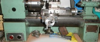
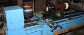
TV 16 lathes were produced in the post-war period at many machine tool factories in different republics of the Soviet Union (Kazakhstan, Ukraine, Belarus). Basically, TV 16 machines were used in various educational institutions to train children, who received invaluable experience in turning. Although in our time the TV 16 machine has already been discontinued, it can still be found in schools, colleges, private workshops, etc.
TV 16 was designed on the basis of the Czechoslovakian TOS MN80 machine, and, despite the fact that TV 16 was produced at different machine-tool enterprises, they did not have any particular differences. They could differ only in the casting forms, and all other internal mechanisms and components were identical.
The machine itself is small in size. It performs functions such as processing various types of metal, boring, drilling, threading, facing, etc.
Specifications
The TV-16 metal cutting machine is designed for the following types of work:
- Thread cutting (inside or outside the part);
- Precise drilling of holes in parts;
- Wasting of metal structures;
- Perform simple types of turning work.
According to the technical characteristics, the following parts can be reproduced on the machine:
- With a maximum permissible turning radius of the product – 18 mm,
- With the greatest distance between the centers of the machine device being 250 mm.
- With a maximum diameter of the workpiece fixed above the processing support - 90 mm.
In terms of dimensions, the small-sized TV-16 machine will fit into a small workshop. The parameters of the machine are small: 1200 mm * 1150 mm * 600 mm, weight – 180 kg.
Characteristics and design features
Since the machine is not professional equipment and has few functional capabilities, it is designed so that a teenager can work on it without difficulty.
The advantage of TV-4 is the indestructibility of the machine. Modern similar foreign-made devices, in the event of any breakdown, will significantly hit your pocket, and besides, it is not always possible to get the necessary part in workshops. The TV-4 model is difficult to break, and finding the necessary spare parts in the event of a breakdown is not difficult.
Overall dimensions of the workspace
TV-4 is a small-sized equipment - 47x102x144 cm and weight - 280 kg. Due to its similar dimensions, the machine is suitable for work in small training workshops.
General view of the machine
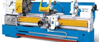
To understand the principle of operation of the unit, you need to familiarize yourself with its main mechanisms. In general appearance, it is a metal structure based on an electric motor, which includes standard elements that determine its technical capabilities.
Rear cabinet
Used to place a shield with an electric motor in it.
Machine bed
It is a load-bearing support that supports, secures and connects all equipment units by installing them on two guide pedestals - front and rear.
Headstock
It is a cast iron body, which includes a speed switch and a spindle and is located on the left side of the frame. It is intended to carry out the movement of the machine, that is, it is responsible for transmitting rotation from the electric motor to the workpiece.
TV-4 machine feed box
Controls the movement of the direction of movement from the guitar to the running shaft/screw, which entails a change in the rotation speed and leads to the reproduction of the desired thread pitch. In addition, the gearbox controls the movement of the caliper. The handle for switching from the drive shaft to the screw provides a lock, which prevents them from being turned on together.
Machine support
Includes three movements in the direction of the bed:
- Longitudinal (with automatic feed) – along the guides;
- Transverse - perpendicular;
- Additional movement - upper slide with 4-position tool holders securing the cutting tool, which can rotate 45° in each direction.
Apron
Designed to select the movement of the shaft or screw into the longitudinal feed of the caliper assembly. If you turn up the left apron lever, the dog clutch will engage, which will engage the gear with the running rack, resulting in the movement of the caliper. If you turn the right lever, the split nut will grip the lead screw in motion and cut the thread.
Tailstock
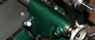
Intended as an installation location for drills, countersinks, reamers and other drilling tools necessary for processing long workpieces and various versions of parts. It can be moved along internal guides located in the frame and fixed into the desired position using a rotating carriage.
Design of the TV-16 screw-cutting lathe
The design includes the following components and mechanisms:
bed
It is intended as a load-bearing cast iron support on which mechanisms and components are installed and fixed.
Headstock
It is installed at the left end of the frame and is intended to perform two functions:
- Reproduce rotational movement;
- Maintain movement while turning metal parts.
Such components and elements as the spindle, bearings, pulley and gearbox help process the product and regulate the speed of torsion of the workpiece.
Machine drive
The machine is driven using an electric motor with a rotation speed of 1400 rpm.
Feed mechanism
Responsible for the necessary movement and amplitude of the caliper, controlled using external handles.
Apron
Attached to the caliper carriage with a screw. Provides movement of the caliper stroke by controlling the handle located on the body.
Important! It is necessary to monitor and provide the apron supports with constant oil lubricant, filling a special reservoir with it.
Caliper
It is a unit that secures the cutting tool and ensures its movement in different directions - inclined, transverse or longitudinal. The holder in which the tool is secured is capable of rotating in four directions by 360 degrees.
Tailstock
Designed for fixing long workpieces and cutting tools. Fixed on the frame using ordinary bolts.
Table
The equipment must be installed on a wooden surface using a fastening screw connection. The left cabinet is designed to accommodate the drive, electrical equipment and a switch, which serves to automatically stop the electric motor, the right one is used as a storage place for working tools and replaceable gears.
What is a lathe: types + design features
The category of lathes belongs to an outdated division of metal-cutting equipment. The history of the development of this direction goes back hundreds of centuries, and continues to develop to this day. All models of turning equipment have a common feature - the ability to process parts that are bodies of revolution.
What problems are solved using turning equipment:
- turning + boring of surfaces of cylindrical or conical shapes + shaped types of surfaces;
- thread cutting. Machines sharpened for this operation are additionally called screw-cutting machines;
- facing and trimming metal parts;
- countersinking;
- deployment;
- coaxial drilling and other types of holes.
There are vertical and horizontal lathes. The distribution is made based on the location of the spindle in the structure. There is also a classification according to the level of automation of the mechanism - manual, semi-automatic and CNC machine equipment.
The classification by type is presented in the table below. The arrangement goes from simple to more complex designs of turning equipment.
| Machine type | Peculiarities |
| Universal | Machines capable of performing several different operations. In the 21st century, the term “universal” is synonymous with the concept of “economical”, because a person can not spend money on purchasing narrow-profile equipment, but perform the entire range of tasks with just one unit. For home use, universal machines are the best purchase solution. |
| Turning and milling | A group of machine tools with manual control. The units are capable of operating in 3 modes - turning, milling and drilling. The last 2 types of work are possible due to a specialized head located above the bed. The independence of the drives allows processing both inside and outside rotating bodies. Low cost and small production capacity for a garage machine are just that. |
| Horizontal bed + CNC | A distinctive feature from the previous 2 categories is the CNC control panel + a casing with flaps that help protect the operator from oil, dust and metal shavings flying during the processing of workpieces with a lathe. The cost puts the purchase for the garage into question, but if you want to get high-quality parts, CNC can help a lot. |
| Inclined bed + CNC | Larger lathes aimed at mass production. The bevel of the bed allows you to get rid of excess metal shavings, which tend to accumulate during long-term operation of the unit. Another design feature aimed at mass production is the tool changer. The price of such machines is several times higher than that of manual machines + they are purchased exclusively for mass production of parts. |
| Pipe cutting | The equipment belongs to the screw-cutting subgroup. The specialization is contained in the name – processing of metal pipes. The key operation of such lathes is cutting inch, metric, cylindrical and tapered threads. Secondary tasks are turning, cutting, boring, and so on. More than 90% of pipe cutting machines are equipped with CNC. |
| Turning and milling + CNC + C-axis | A modern solution that expanded the functionality of machine tools, turning it into a hybrid one. The innovation in the form of cutters and drills with a personal rotational drive + CNC brought the equipment to a new level of work. The “C-axis” allows you to control through the CNC not only the rotation speed of the workpiece, but also its angle of inclination. |
In 2022, C-axis lathes with a counter-spindle were put into serial production. The tool is located at the tailstock site and acts as a workpiece interceptor.
In this way, the machine can process the part on both sides without direct human intervention. The operator puts the work algorithm into the CNC program and simply goes to drink tea.
8 structural units of the TV-6 lathe
Installation features
In addition to the machine, a table is supplied. It is necessary to accurately fix the equipment on the wooden surface of the table (you can use a horizontal level) using six screws. Particular attention should be paid to grounding. The grounding wire must be passed through special holes in the frame and secured with bolts.
Before operation, it is necessary to thoroughly inspect and test all parts and assemblies.
How accurately the equipment is installed, the machine will operate accurately.
Photo and description of the device
The simple design of the equipment allows even a novice turner to quickly become familiar with the technological process of processing metal products.
General form
The base is made of cast iron; the machine is attached to the tabletop using screw holes. In the center of the table there is a drawer for storing all kinds of tools and accessories.
The right box is designed to store cutters and gears.
Inside the left box there is a drive consisting of an engine, an intermediate shaft and two gears. The intermediate shaft regulates the degree of belt tension with an eccentric device that rotates the main shaft. That, in turn, together with the engine, is equipped with stepped pulleys, ensuring the rotation of the pulley at six different speeds.
The tool holder moves thanks to a lead screw and a nut installed in the front compartment of the working base.
Drawing
- bed;
- headstock;
- machine drive;
- feed mechanism;
- apron;
- caliper;
- tailstock;
- table;
- electrical equipment;
- accessories and tools.
Location of controls
The list of main machine controls includes the following mechanisms:
- switch;
- handle that changes the spindle speed;
- handle that changes the direction of feed;
- push-button module;
- lever securing the cutter head;
- master nut release lever;
- lever for moving the upper slide;
- lever for moving the cross slide;
- a handle that secures the position of the tailstock quill;
- flywheel for axial movement of the tailstock quill;
- flywheel for longitudinal movement of the caliper.
The push-button station and spindle speed switch are located on the front surface of the table, the rest are directly on the unit itself.
Headstock
The headstock consists of a body, a metal bit and a shaft with a three-stage pulley. The main task is to rotate the working cardan connected to an angular contact bearing mounted in front of the shaft.
The main shaft also has a pulley that provides a given rotation speed by the electric motor. The bit provides reverse rotation of the shaft.
Two tapered bearings hold the spindle and pulley. By changing the location of the bearing using a nut, the gap between it and the spindle assembly is adjusted.
Speed and feed switching device
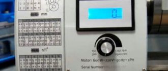
The TV-16 does not have a gearbox or feed switch. The spindle speed is adjusted by changing belts between the pulley gaps, thus obtaining one of 6 modes. By changing the gears in the guitar, you control the pitch of the thread being cut or the feed speed.
The gear unit is located in a closed box, on the door of which there is a switch that stops, for safety reasons, the operation of the equipment if the door is opened during the working process.
Apron
The apron, controlled by a handle on the body, drives the caliper stroke. The carriage is attached to the apron of the device with special screws.
A detachable nut located in the apron is driven by the handle. When the nut is engaged, the tool holder is fed by the lead screw. When turned off, it is performed manually by rotating the flywheel.
Caliper
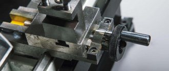
The support is responsible for fixing and moving cutting tools in inclined, longitudinal and transverse directions. The assembly includes a tool holder, a carriage and a slide.
The carriage moves parallel to the frame along guides; all components of the support are installed on it. The lead screw and rack-and-pinion gears provide longitudinal movement of the caliper.
Tailstock
Tailstock with hexagonal guides ensures long parts are positioned correctly as they move along the bed. Acts as an additional support and is fixed with a groove bolt.
Operating rules
When working on equipment, you must adhere to the rules of its operation. First, monitor the condition of the device:
- Perform a thorough cleaning and external inspection of the unit at least once a month.
- Make sure that there is no rust on the surface of the machine. To do this, it is necessary to coat the surface of the connection between the core and the armature with oil, and then wipe it dry so that the oil does not cause gluing of the component parts. Lubrication must be carried out in accordance with the diagram specified in the instruction manual. This requires monitoring the oil level in the system. It is also recommended to use lubricants specified in the service manual.
- In addition to preventive inspections, it is necessary to conduct a thorough inspection and assessment of the condition of the equipment annually, as well as perform routine repairs of components: the condition of the switch, nuts, cleaning the electrical cabinet and other types of work.
- Equipment contacts are made of materials containing silver. Accordingly, there is no need for careful care and adjustment of their condition. In case of any damage, they are replaced with new ones. Performing contact stripping may result in blackening, which may affect the functionality of the equipment.
Where to buy and what to look for when choosing
Since the machine has been discontinued, you can now buy it only from the reservation of some enterprise, or from private individuals. In any case, when purchasing this used equipment for a home workshop, you should take a number of the following measures:
- Check the serviceability of the machine on site with the current owner.
- Assess the condition of the parts.
- When purchasing, it is recommended to go through all the parts to look again and assess their condition.
You can buy such equipment on Avito for around 20,000-40,000 rubles. And most often it is taken for personal use, for small turning workshops or to meet the needs of a car service center.
Safety precautions
Following safety precautions helps prevent injury when operating equipment.
To prevent accidents from occurring, the following rules must be followed:
- It is not allowed to perform cleaning and lubrication work on equipment components during its operation.
- It is not allowed to leave the equipment turned on and move away from it; you must first disconnect it from the electrical network.
- It is necessary to ensure good lighting of the work area.
- If a breakdown occurs, you must stop working immediately.
- In the event of an emergency, you must immediately disconnect the equipment from the electrical network.
Instructions for first start-up and operation
Before operating the machine, after unpacking, proceed to installation and testing of the equipment:
the machine is screwed to the table surface with 6 screws included in the kit; check the position of the drive belt on the drive pulley; taking into account the dimensions and weight of the machine, check the correct horizontal installation; grounding is carried out through the side holes of the frame, the wires are pressed with a bolt; the power cord from the switchboard, which must be equipped with fuses, is insulated; A thorough inspection of the machine is carried out, paying special attention to the components. If necessary, change the lubricant; a test run is carried out, first idle, then with load.
Analogues of the machine
The purpose of using the TV-16 machine is to train and instill skills in students to work in metalworking. TV-16 is mastered by the student quite quickly, and the skills of working with it can be easily transferred to equipment used in large enterprises. The TV-16 was discontinued because it could no longer cope with the required volume of work, which led to the emergence of modern analogues with greater possibilities of use. Based on common machine models, including the TV-16, improved designs with an original layout are created. Imported analogues of lathes have become especially popular.
Lathe TSA 16
The Polish lathe TSA-16 has the following advantages:
- Easy controls.
- Reliability.
- The ability to process wooden and plastic workpieces (not only metal).
- High precision.
- Low cost.
- Small sizes.
Electrical equipment
All electrical equipment of screw-cutting lathe 16 is designed for the use of power units. It is connected to a three-phase network. To ground the device, an ordinary neutral wire is used. It helps protect not only from short circuits, but also from network overload, as well as a number of other factors of electric current breakdown. The complete connection diagram is visible in the photo below.
To provide contacts, relay contact equipment is used. It hides in the electrical cabinet, which is located on the back of the machine. You can see it on the headstock housing of the equipment.
Before making a test run, you should make sure that the network frequency and voltage fully comply with all TV-16 parameters. It is permissible to connect equipment to the network using copper wires, which in cross-sectional diameter are equal to those of the conductors in the machine circuit. The grounding is connected using a bolt, and before starting, the operator needs to make sure every time that everything is fine with the connection.
TV-16 electrical circuit diagram of the machine
Symbols for the TV-16 electrical circuit.
Rear assembly design
The TV-16 metal lathe has a simple design, one of the most important parts of which is the rear assembly. Its main function is to support long workpieces and drill holes. It moves only in the longitudinal direction using triangular guides.
If the design processes cone-shaped parts, then the rear assembly can make perpendicular movements using a screw. Installation of a center with a cone is possible only with the help of a hole that is prudently located in the quill.
Purpose, area of application of the machine
TV-4 is a universal, simplest lathe that performs many operations on the outer and inner surface of a metal workpiece, turning it into a finished part. TV-4 is more popular in use as a training option for turning equipment in various educational institutions. For this reason, the machine is also called “school machine”. This is not professional equipment designed for large scale production, but equipment that is only suitable for training. The main purpose is to enable students to gain minimal skills in the manufacture of metal parts.
TV-4 equipment can perform the following types of work:
- Boring and grinding the surface of a steel workpiece by rotating.
- Trim ends with a high degree of precision.
- Drill holes.
- Cut different types of threads with different pitches.
The functionality of the machine is small, it is simplified with the possibility of reducing the cost of the design. Modernized equipment with improved technical characteristics has expanded functionality.
My steps to restore the machine.
Complete disassembly of the TV-16 lathe and evaluation of the work.
The machine is important to me as a tool; I really need diffusers for my aircraft model engines, which I will install on micromotors. Therefore, I decided not to delay the process. I set myself a deadline of the end of October 2022 to do something on the machine. Every day when I came home from work, I tried to disassemble one component of the machine. Moreover, he put the parts, bolts, screws in separate containers. It’s easy to confuse or lose something without this.
Almost every component of the machine was a struggle, although the machine was well lubricated and nothing jammed. But I had to look on YouTube and also search on the Internet to see how the machine components are disassembled. I didn't want to damage anything. Each node has its own trick, do not rush to use force when disassembling.
Having finished disassembling the machine, the question arose: to make a candy out of the machine or to launch it as is without extra financial investments. I decided to launch it and then we’ll see...
PS after two years of use. The bet on launching the machine as is has borne fruit, I use the machine in the apartment. It immediately became clear that the machine was just the beginning. For successful work you need good cutters, blanks, drills, dies, taps, measuring tools and fixtures. All this was slowly sought out at local flea markets. Even now I understand that I don’t need such a powerful engine. It is necessary to place the frequency converter and the motor directly. The belt drive, together with other elements, creates vibrations. As I understand it, this is normal for this model of the TV-16 lathe.
bed
The bed of my TV-16 lathe was slightly damaged by “barbarians with hands.” From the tailstock side the machine was beaten, or something was hit with it... On the cartridge side, the caliper did not reach the end. There were traces of blows, with a file or something else.
I did not remove the headstock with the spindle because everything rotated well there, there was no play or other problems. Unless the edge of the spindle behind the thread was slightly damaged by someone. I had to correct it a little with a diamond file. Fortunately for me, the frame as a whole was not very worn. I took the measurement with a micrometer, the deviation was no more than 0.02 mm, which is normal. In places where there were “abrasions” and unevenness, there were naturally errors...
The damaged areas were carefully ground down using a file and small needle files. Ultimately, I brought the surface to condition with a homemade scraper. He did it as well as the tools allowed.
Lathe lead screw
To completely disassemble the caliper, you need to pull out the machine's lead screw. This is where I ran into some minor difficulties. The screw seemed to be caught in a bronze sleeve. I could hardly pull him out. I tried to lubricate it and put it back in place. It turned out that the edge of the lead screw was slightly deformed by the impacts. I ground off the deformed edge. The screw began to rotate better, but still with difficulty. I already started looking for a reamer, I thought the bronze bushing was damaged. Fortunately, no, the screw was jammed due to me unscrewing the “thing” where the screw is inserted on the right side. There must be exact alignment in this place, otherwise there will be a skew. After tightening the screws, the lead screw began to rotate without problems.
PS after a while I started the guitar and the lead screw. I had to sharpen the planetary gear a little. The bronze insert was badly damaged. There were also inaccuracies when the gear rotated. After careful manipulation, trial and error. The lead screw started working. By generously lubricating the guitar gears with thick lubricant (salidol), closing all the “cracks,” I achieved a significant reduction in noise.
Longitudinal and transverse feed support
Luckily for me, the caliper was in good condition and did not require any special manipulations. Although I spent a lot of time trying to completely disassemble it. There is a lot of information on the Internet showing how to do this. The main thing here is not to rush, not to put pressure or hammer.
Electric motor
It seems to me that the engine used to be on a water pump, although it was rusty and dead on the outside, everything inside was functional. The shaft on one side was lengthened by welding a piece and subsequent processing.
There were 3 wires sticking out of the engine, I tried to connect the whole thing to an alternating current network of 220 Volts, through a 10 microfarad capacitor, the engine started working. But the noise of the engine immediately became apparent, as well as the pulley that had been machined by someone was very heavy and did not stand level. All this resulted in strong vibrations, similar to the vibrations of a mobile phone... Such a machine cannot be used in an apartment. The neighbors won't stand it.
Having disassembled the engine, I checked the bearings; one of them had slight seizure. Replacing it, the noise decreased significantly. It was necessary to place strips from a beer can on the shaft under the pulley, thereby balancing the position of the pulley on the shaft.
I managed to achieve an acceptable level of noise and vibration. After playing with the belts, I achieved a slight tension on the belt, but the vibrations were minimal. For my needs of working with brass and caprolon, this was the solution.
10 microfarads of capacitor was not enough for the engine, 20 was already too much, so I chose the middle.
Scroll chuck
The photo shows that the chuck installed on the lathe is gigantic in size, 165 mm)))) for the TV-16 go. A little more and he will scratch the frame. First of all, before seeing the machine live, I began to look for a replacement for it. After reading the forums and asking around, they recommended that I take a 125 mm cartridge and preferably a Polish high-precision one. I was afraid that the cartridge might not fit my flange, but in vain, because I still had to grind the flange. Not deciding to buy a cartridge from Russia, I began to look for it in my area. At flea markets and bazaars, you can find spare parts for lathes, but very few. I found 125 cartridges, probably from a TV-6 machine, but their condition confused me. Rusty, beaten, and even the cams are not original in some places... This option was not suitable for my high-precision aircraft modeling work. I've been looking for a cartridge for several months now and couldn't decide on a size of 80-100 or 125 mm. Time was running out, by this time the engine was already spinning and I wanted to start the machine. Once again walking through the Sultoni-Kabir bazaar, one of the sellers, who already recognized me by sight, offered me an 80 mm cartridge. I began to consider wiping it from dirt. I see the inscription CT80P, I think wow, you need to take “Polish”. I began to check how the cams were moving, but there was no key in the entire market, so I had to dodge and turn with a reamer... The cams seemed to be moving, but not well. I decided there was no need to take it, but the stated price alarmed me. He began to bargain, the seller gave up a fifth of the price, but no more, saying that he himself bought it yesterday for a slightly lower price. And then I had a conversation with a flea dealer from another bazaar, who told me that yesterday someone brought several small cartridges and quickly sold them out... Our resellers live in the morning, come at 5 and go until 7 in the morning, and then go to their points at the bazaars.
The ST 80P cartridge was heavily soiled and rust appeared in places. The fists moved very, very tightly. There was a visible notch on the side of one cam, damage that slightly compressed the path of the cam. I bored out this place with a diamond file, the usual ones slipped like they were on glass. When I removed the cams, I was disappointed (((one of the cams No. 2 had damage. 2 teeth were broken but they were not there. Also, the other cam had a crack.
I washed the cartridge and all the parts in gasoline with a brush and some fine sandpaper. It turned out shining like a new cartridge. The fists still moved very tightly. It was similar to the density with which a piston moves in the cylinder of a model aircraft engine. With minimal manipulation of the diamond file I achieved a smooth glide. I assembled the chuck, fortunately it worked when clamping parts less than 9 mm, as well as more than 30 mm. I'm still looking for a replacement for the broken cam. I didn’t make any claims to the seller because the cartridge, even in this form, suited me for doing small jobs like a vice.
In search of a cam/jams for my Polish CT80P cartridge, I again searched all the bazaars and flea markets... I didn’t find anything, but I decided to buy a Soviet 80 mm cartridge, as it was good for me, and I agreed on the price. I bought several cutters, reamers and a chuck, and I asked for a good discount. The new cartridge went through the same maintenance procedure. Everything about it suited me, although it seemed to me that the Polish language was much better. Looking ahead, I will say that this cartridge copes with its role 100%, especially for a beginner, learning with it is the best thing.
I have the cartridge, all I need to do is give the flange to a “professional” turner for modification to fit my 80 mm cartridge.
Plan washer (Flange)
In search of a plan for the washer (flange), just like with other parts, I scoured the city several times, asked a lot of people, and even thought about buying a flange on the forum. But the flange is such a thing that it needs to be adjusted individually to the machine, to the chuck. So I finally decided to bore my 165mm flange to 80mm. You couldn’t do this on your own machine or in your room. Then I went to the “turners”. As luck would have it, on weekends they don’t work when I need it, and in the morning I can’t get them on site. I had to spend several days trying to find someone who would undertake to make my modifications. Moreover, I myself could not find the main “turner” and had to contact through my wife’s brother, who works in the neighboring furniture workshops. He charged him 1,500 rubles in Russian money as “his friend,” but after haggling they agreed on 700 rubles…. I had to wait a week and then a couple more days to finalize the flange. As a result, my nerves were on edge. You probably understand now why I bought myself a machine, and why turning a simple diffuser in my area is very difficult and not economically profitable. You’ll probably say that there are also turners, yes there are, but their rates are the same or higher, and often they don’t want to take on small things (((In our area, the minimum pension is 1,500 rubles, so you can understand the difference in prices.
With the installation of the puck plan we had to do the same dance. They didn’t make holes for the mounting bolts in the flange, and what they would have done was to wait and wait. In truth, I was fed up with their “tomorrow” so I decided to drill it myself. Of course, drilling with a screwdriver is rough, but you can do it right now. I drilled with small errors, so that the holes had to be expanded and adjusted. But what happiness awaited me when the machine started working)))))))
Tailstock TV-16.
The tailstock probably suffered the most in the hands of the previous owner. From the marks of the blows one could guess that it was used instead of a hammer. I smoothed out the strong bumps with files. The final processing was done with an improvised homemade scraper. The tailstock quill, like the rest of the parts, had to be cleaned of paint and rust. We must pay tribute to the previous owner, the machine was very well lubricated, so there was not a lot of rust.
Finally
In conclusion, I would like to say that the TV-16 machine pleases my eyes every day. He stands in one of the rooms and contemplation alone motivates. Apparently I, as a man, am not very indifferent to such things...
In order to be able to work successfully, I had to fight vibrations; I didn’t bring the machine to perfection, but rather launched it in a hurry. Because I could no longer invest any more money. But even so, I was able to sharpen diffusers for my aircraft model engines myself. I especially liked caprolon, this material is freely available on the market, but with duralumin everything is complicated...
If I had the opportunity to take a 125 mm cartridge now, I would not change my 80. When performing my work for aircraft model engines. (small things) the use of such a cartridge is 200% justified. Perhaps I am not experienced, but there are more possibilities for moving the caliper.
